
This week assignment was add an output device to a microcontroller board you've designed and program it to do something
So I basically continued the work that I was making on the input devices week, but instead of using the LEDs as inputs, I should use them as outputs. It means that I need at least make them blink!
To make them blink it is easy, and we've done it before in the embbedded programing week, but my challenge this time is to make them repond the input singnals that I made before, I mean, light them up after recognize that the LED was pointed by the laser.
However I started by just making them blink. I wanted to make some code at the setup for sanity checking before start run the program at the loop with all the functions used in the input week. For this was pretty easy, I just had to figure out some for() functions to change the state on the ports, wait for a while to you see that the LED was light up and then light them of to go to the next LED.
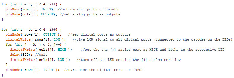
Basically I worked again with arrays, pinMode(), digitalWrite() and delay() functions. As this first step I was not responding to any input measurements, just wanted to blink each of the LEDs to make sure that all of them works. It is a good practice so I could use this as a sanity check at the setup() function. To do this basically the steps are:
1) Set all the used ports as OUTPUT.
2) Set, once per time, Digital ports as LOW.
3) Set, once per time, Analog ports as HIGH.
4) Wait for a while to you see the LED light up.
5) Turn off the LED by setting the Analog ports as LOW and making especified digital port back as INPUT.
Remember that I set those ports that way because on my circuit the anodes are conected to analog ports, and cathodes to the digital ports, as showed before on the Input Devices page. Here is how the code looks like and a GIF of how the LEDs blink.
You can find this file here: justblink.ino
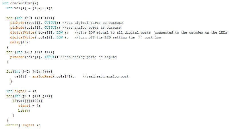
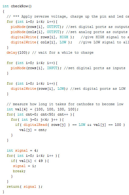
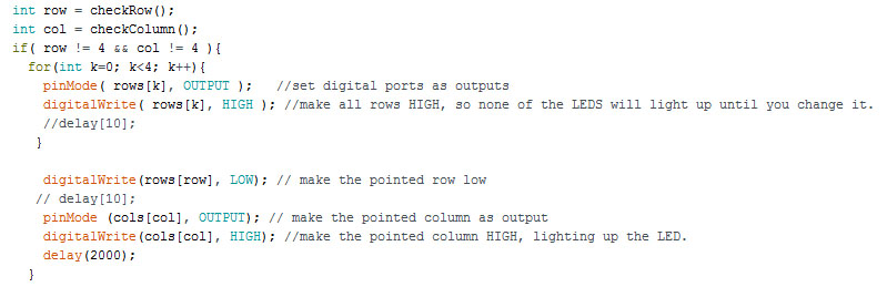
I started to work on the programming to light up the LEDs after recognize which one was being pointed. First thing I did was create two functions: checkRow(); and checkcColumn(); that would return the number of the Row and Column that the laser pointer was being pointed. Basically I changed the programming showed before on the Input Devices pages, to after it recognizes which row or column was being laser pointed, instead of printing it using Serial.print(); I return a signal to the main loop with this information. Knowing which LED was being pointed, I would be able to set its ports to light it up. This is how those parts of the code looks like:
While making the programing I realized that it was not working. By checking the programming again, I realized that the function to light on the LED was to fast that you don't have enough time to see it on, so I added a 2 seconds delay after light it on to we have enought time to see it. Here is how this part of the programming looks like:
And a small video of it:
The file of this programming can be found here: _1stattempt.ino.
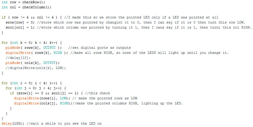
At my second attempt I tried to save in two arrays the status of each column and line, and saving them I exected that I could light different LEDs together, not one at once as in the first attempt. I kept the functions checkColumn() and checkRow() as it was, and worked on the setup() and loop().
So I created the two new arrays at the setup(), setting initial value 1 for the rows, and 0 for the columns, to make sure that the LEDs start as off. Then at the loop() I check the returned signals from the checkRow() and checkColumn(), and at each time that I receive these information I change a value in the new arrays, if is a row I chage to 0, if column I change to 1.
Then I created the two for() to light the LEDs on but with an if() inside it, checking the values of the two new arrays and lighting up both the new pointed LED and the columns and rows that was pointed before. Here is how the code looks like:
There was two problems with this approach.
1) If I want to light up LEDs on different rows and columns, I end up lighting up unwanted LEDs, because in each column, all LEDs has its anodes conecteds, and in each row all cathodes are also connected. For exemple, if I want to light the entire diagonal, I end up lighting up the whole LED matriz.
2) The LEDs was blinking too much instead of just keep lighted. I kind of undsertand because it needs to change the ports function to INPUT to check if the LEDs was being pointed, but them I started to question me if the microcontroler would need too much delay to get thoses values as I presupposed.
Here is a video of how this attempt looks like:
I don not adive to get this, but if you want here is the file of this atttempt: _2ndattempt.ino.
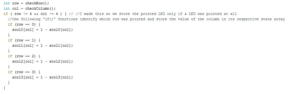
Then I finally got to the final adjustments. What I did to solve the previous problem was basically to creat one array for each column that would save which LED was saved for each line. I initialized all columns with 0 (meaning that they are set LOW) and change those values when the LED was pointed for each row.
Also I searched how I could wait less time when needed, instead of using the standard delay() function, I included #include
Besides that, I also managed to be able to turn the LED of if you laser point to a lighted on LED.
The changes that I made was:
1) Added one if() for each returned value of row from checkRow() and inside this if I store the value returned from checkColumn() to the respective array.
2) To turn the LED off if it was previously on, instead of give 1 to the column state, as showed in the second attempt, I used state = 1 - state So if it was 0 before, it wil become 1, and if it was 1, it will become 0.
3) I set only one row to LOW per time, and again using a if() function I light up the respective columns of pointed LED in that row especifically, adding also a small delay to allow us to see that the LED was on


And here is a video of the final result
I think you will understand better by reading the programming
You can find this programming here: _3rdattempt.ino.
1) Use Port manipulation to read and light up the LEDs would make it a lot faster
2) Use some debouncing for when I laser point to the LEDs
3) Use a translucedent acrylic to avoid the Laser light reflect at the LED and come back to your eye. Actually I tested it with an inventables part # 24130 and it worked pretty well!
4) Make a bigger matrix, for the final project I am thinking in a 8 x 8