WEEK 9
MECHANICAL DESIGN
ASSIGNMENT
- Make a machine, including the end effector, build the passive parts and operate it manually.
Preperation
This is a two week assignment to learn and make a machine as group assignment. We formed a single group of 9 students to make something useful machine for the Lab. Actually our plannings were started from week8 and identified some projects for this week. As a team member, I also contributed by suggesting some interesting projects. Finally our team decided to make a U-ARM which is an existing project. Let's Introduce Our team and other details .
- Ganadev Prajapathy
- Jim J Seelan
- Jithesh Gopal
- Rahul S Rajan
- Renjith M S
- Sachin Salim
- Sreejith Mohanan
- Syed Junaid Ahmed
These are my project proposals for this week. After a long discussions with our instructors , we are finalised to replicate the U-arm with added functional elements.
FAB-ARM
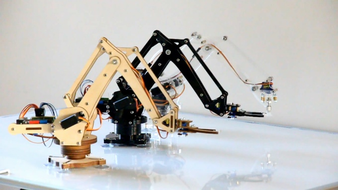
FAB-ARM, this is the name we have given to our robotic arm made first in Fab Lab Kerala. It is a miniature 3-axis parallel-mechanism robot arm called U-Arm, modeled after the ABB PalletPack IRB460 industrial robot arm. It is made up of laser cut acrylic or wood parts, powered by standard RC hobby servos, and controlled by an Arduino-compatible board. The basic design is Arduino-controlled, using 3 servos, with 3 degrees of freedom. Three servos on the base control the main movement of the arm and the last servo on the top moves and rotates the object. We planned to make a common arm with multiple end effector, If we use a servo for pick and place will get one more degree of freedom. Later, suggestions came from team menbers to add a linear rail to it additionally, so that it will move through the rails which add one more degree of freedom also which help us to move objects to do pick and place for a long distance. To know more about the project U arm
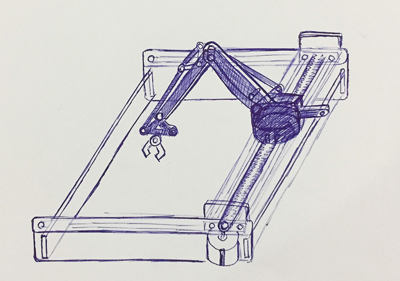
Sketch of FAB-ARM (by Sreejith) Proposed FAB-ARM(U-ARM)
My Tasks
After Neils lecture on Wednesday 22nd March 2017, Thursday our team meeting was called and in the meeting finalised the project and Our team leader divided the individual responsibilities of each persons and shedules to finish the tasks. The task assigned to me i have drawn in draw.io is shown below.
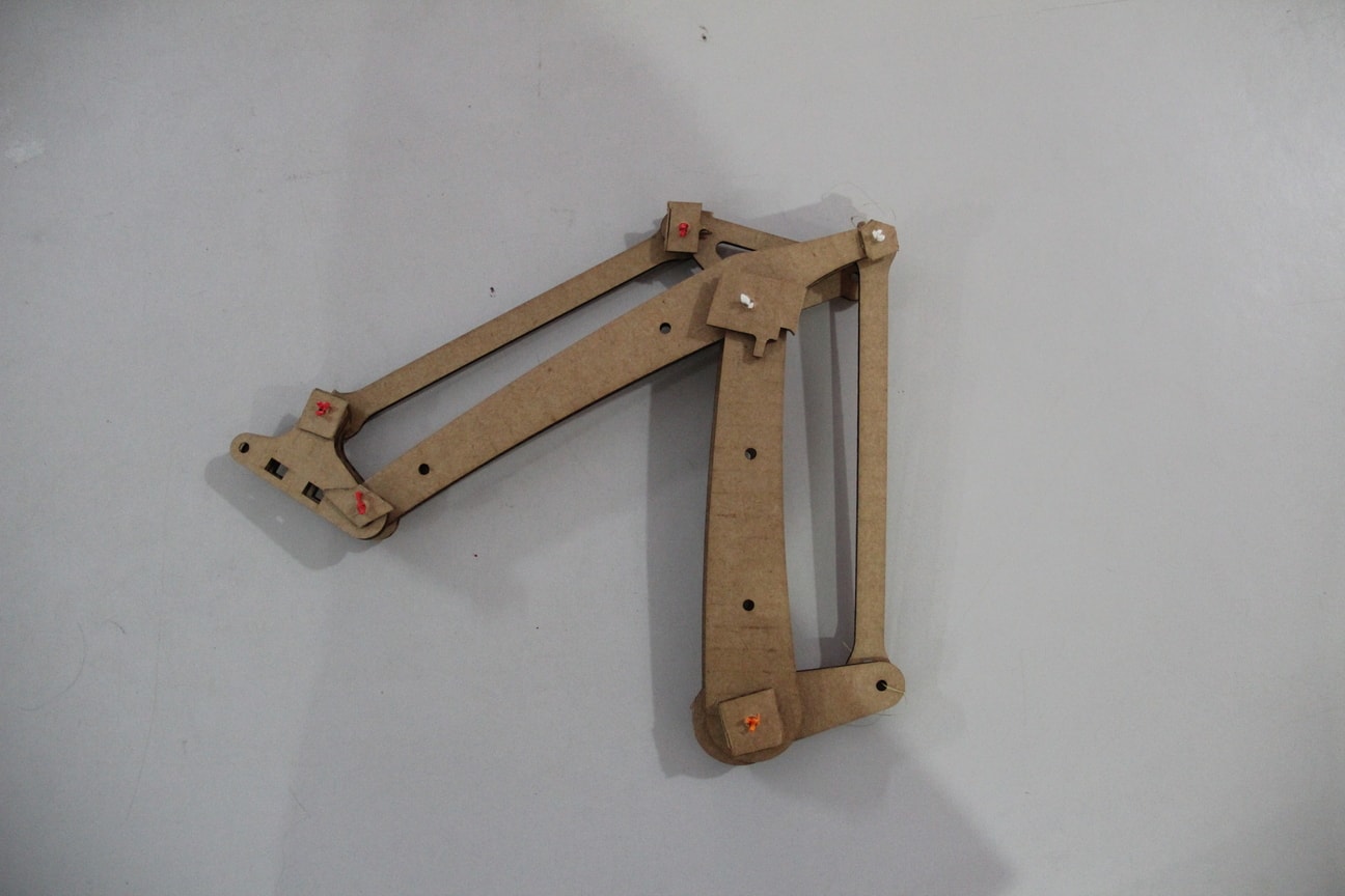
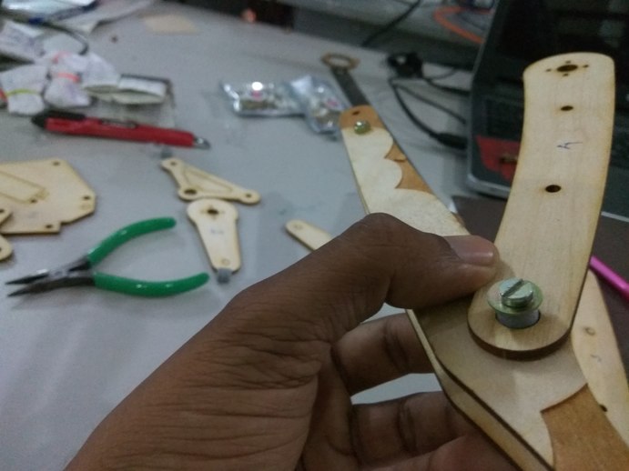
We have no previous experience in making machines , So we planned to cut and assemble the arm parts in 3ply cardboard sheet for the proof of cocept of the design. Sreejith was taken initiative to cut the parts in cardboard sheet, he has identified the parts that is required for assembling the arm. After cutting the parts in Laser machine and we assembled the parts. We have used broken PLA pieces and cardboard sheet pieces for joining the arms instead screws. Finally the assembly completed and able to move the arm. The below shown image is the assembled cardboard version of our arm.
I. Design, Fabrication Of Standoffs & Spacers
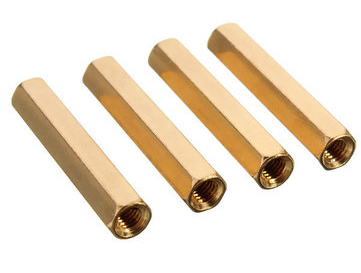
Design of Standoffs
A standoff is a threaded separator of defined length used to raise one assembly above another. They are usually round or hex (for wrench tightening), often made of aluminum, brass, or nylon, and come in male-female or female-female forms. In our project we require M4 and M3 Standoffs of different sizes. The total requirement of standoffs for our project are summarised below.
Standoff requirement for FAB-ARM
- Stand-offs M4X10mm - 4Nos
- Stand-offs M4X15mm- 1No
- Stand-offs M4X22mm- 4Nos
- Stand-offs M4X55mm- 2Nos
- Stand-offs M4X65mm- 1No
- Stand-offs M3X8mm- 2Nos
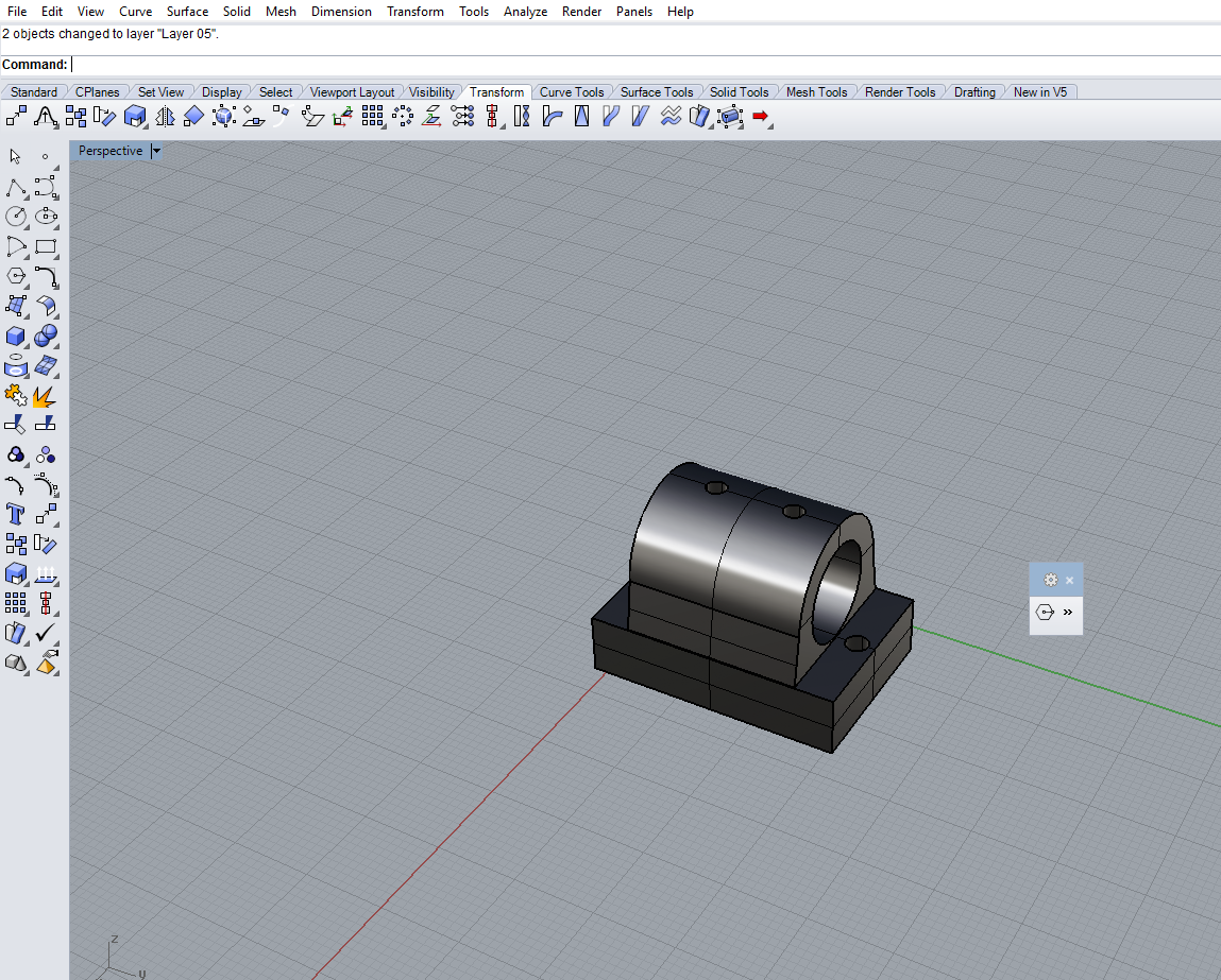
We have searched the standoff availability in local shops but we didn't get the brass standoffs. So we planned to design and 3D print it on 3D printer with plastic as the replacement for brass standoffs . I designed the hexagonal shaped standoffs using Rhinoceros software. I have given sufficient width to walls to get enough strength to the standoffs.
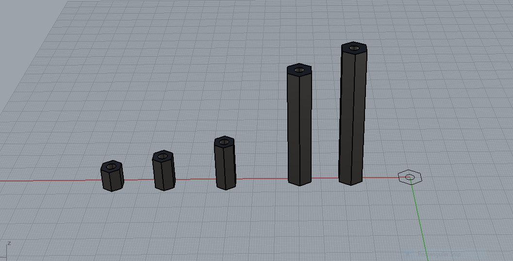
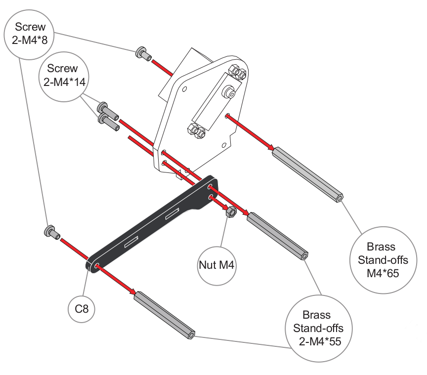
The 3mm standoffs were made for holding the control board and all other arm parts needs 4mm Standoffs. The picture shown below is the assembly diagram of the arm in that we can clearly understand the use of standoffs.
Challenges faced
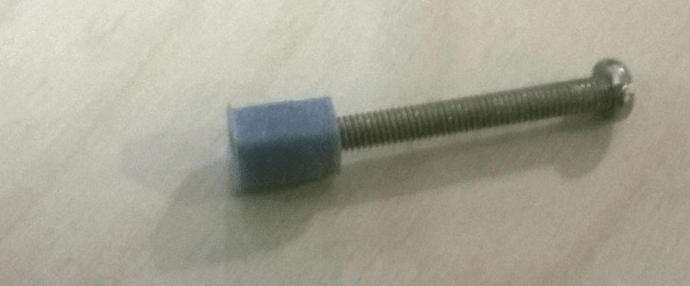
Actually the requirement of the standoff was 4mm , so i designed accordingly. After completing the design the files were exported into .STL format and printed it using Ultimaker 3D printer with PLA plastic. First i made a sample standoff of M4X10mm size and checked with the M4 cheese head screw, since the screw is having threads, and it showed little bit tight which is not desired. Based on this observation, I changed the inner dia of the standoff from 4mm to 4.1mm and printed, this time it worked correctly.
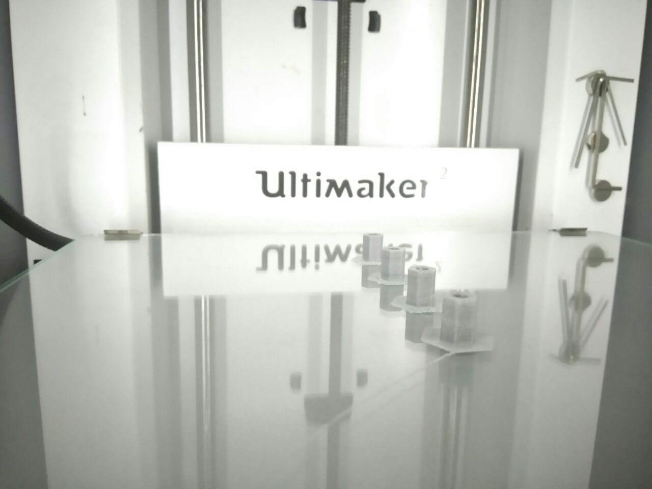
Corrected design print on Ultimaker 3D printer, print was given in batches. The image shown below is the printing of 10mm standoffs in ultimaker.
Design of Spacers
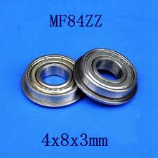
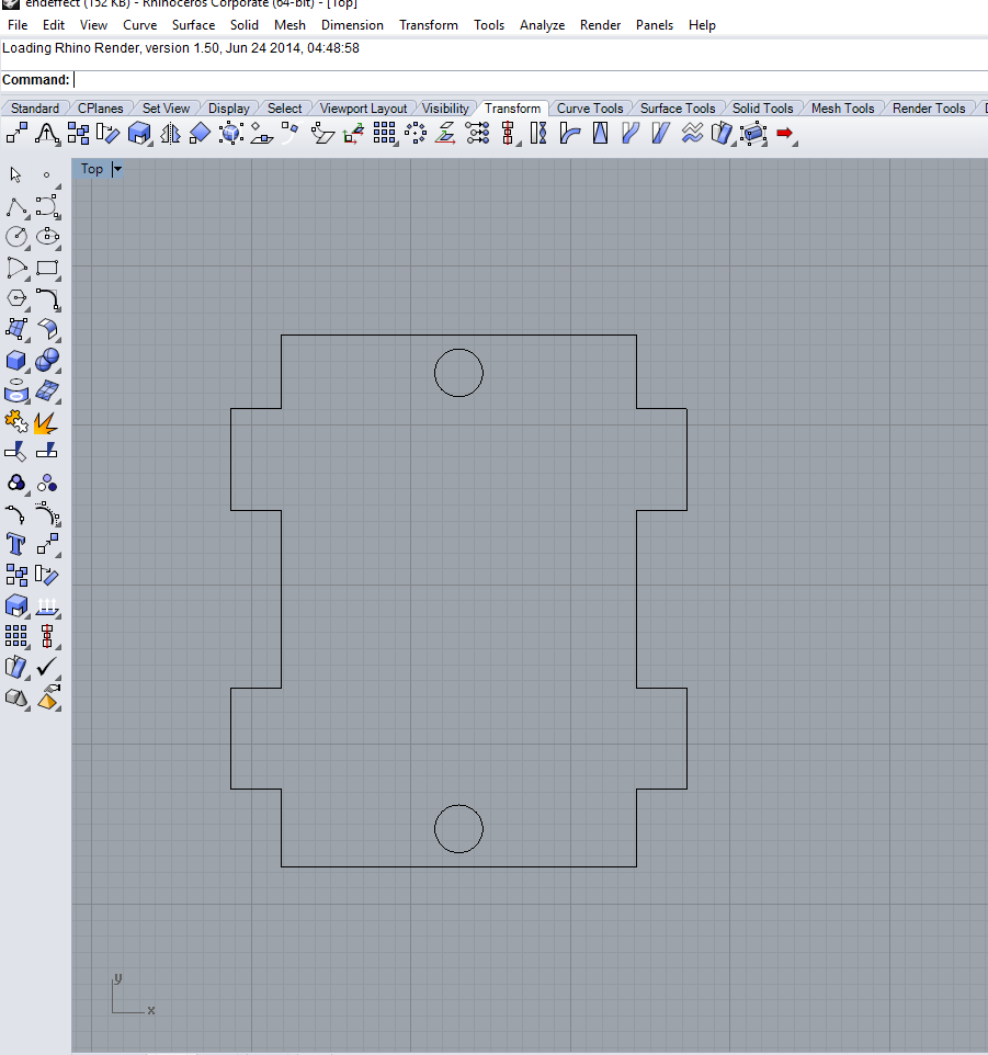
My next task is to design the spacers, Actually the movements of the parts are being done by the use of flange bearings like the one shown below. We require a total of 24 Nos of Flange Bearing MF84ZZ. This is a small flange bearing and is not available locally, So replacement to that we planned a spacer of dimension of 4.2mm inner diameter and 8.7mm outer diameter. Designed the spacers in Rhino and printed using ultimaker.
Design of spacers
The image shown below is the design of the spacer and assembly of the spacer with the arm parts.
![]()
3D printing and assembling of spacers. The right one shows the assembly of spacer into the arm
![]()
Download standoff&spacer design files (.zip)
Assembling
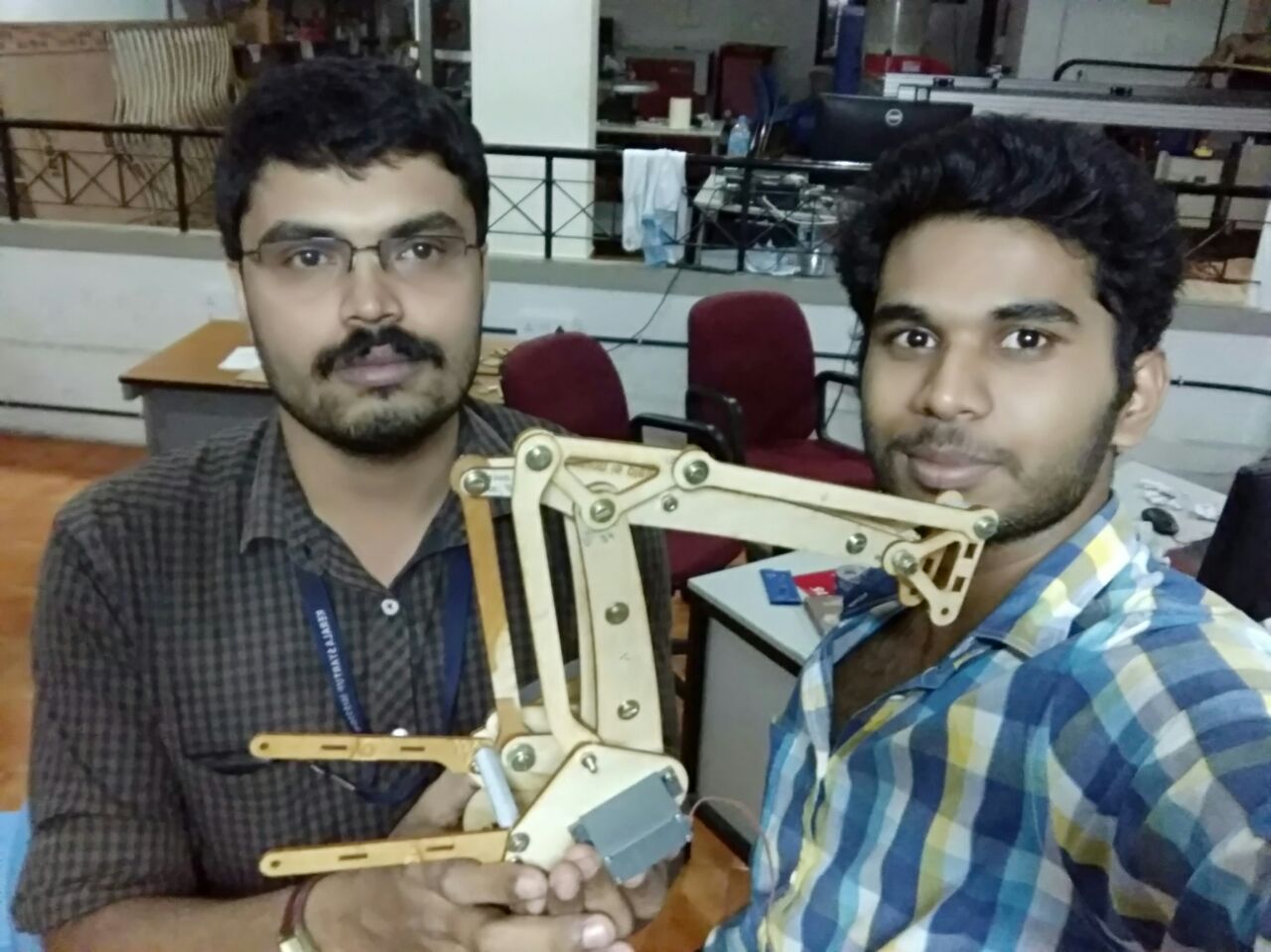
After assembling the cardboard test cut parts, We fabricated the total arm in laser cutter using craft wood, here we used some scrap craft wood pieces to cut the parts. The files used are from the original design files and Syed, Ganadev & Sreejith where did the laser cutting activities. After cutting the parts we started assembling of the parts with the screws and other fasteners by referring the assembly instructions form the documentation page. Assembled the servos into the side plates and i feel it was the difficult part of the project since, it is having lots of parts and fasteners with different sizes. It's taken almost 6 hours to complete the assembly of the parts. The selfie with Fab-arm was awesome ,because we have finished it in morning 2:15 am.
Servo Trouble shooting and Load Testing
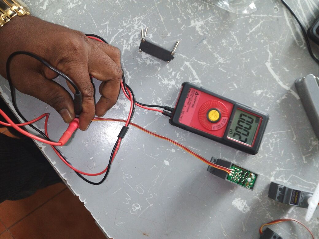
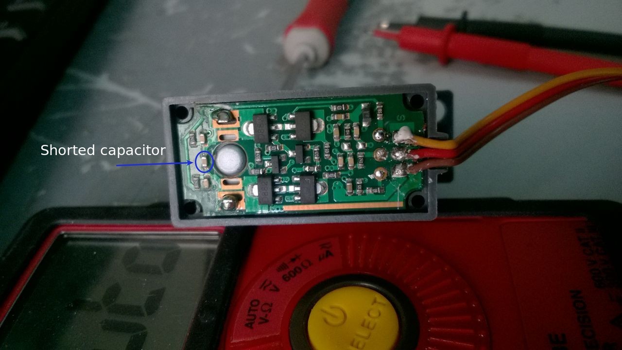
We require 3 Servos to control the arm. This week the assignment is to build a machine and move it mechanically ,but we planned to move the arm electronically by driving the servos using the arduino. Renjith was the incharge of load testing, he started to testing of servos individually, while testing individual servos it is observed that one of them is not working and while connecting to arduino the arduino is getting some errors.In order to figure it out the error i checked the servo and found that the VCC and GND line is short in servo. So I removed the servo cover and done some passive measurements and found that in the control board one SMD capacitor is short, I am not 100% sure that this was the issue with the servo, for time being i kept it aside for further analysis. In the picture showed below you can see the multimeter reading in between VCC and GND.
Load testing
Load testing is performed to determine the maximum torque of the motor under different load conditions. We have Hobbyking HK15138 tandard analog servo which is having a torque of 4.3Kg at 6V, first we have to test it with our arm before integrating it to the arm. The program to control the motors are done by Renjith, after completing the arm assembly the servo motor was integrated on the arm and we have done load testing, used Neodymium magnet as the load . Placed equal quantity of magnets on the two sides of the arm on the M4 screws and done the test. The video shown below is the load testing of the arm assembly. We found that at 5V the arm is capable to a maximum load of 60 grams and the craftwood arm parts weighed around 59 grams . So in total it taken maximum 110gm of load at 5V. I think before assembling the servo , we should do the load test. In our case we don't have any higher torque servos available in our lab . So we planned to use this for the first version prototype and to procure new servos or to replace with stepper with higher torque for our final prototype.
Pen holder design
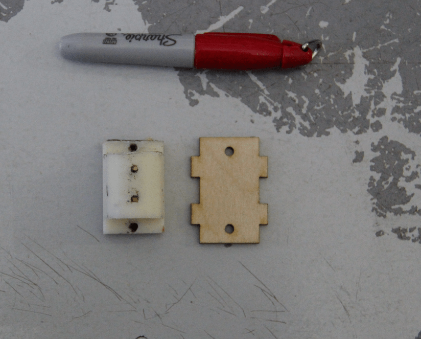
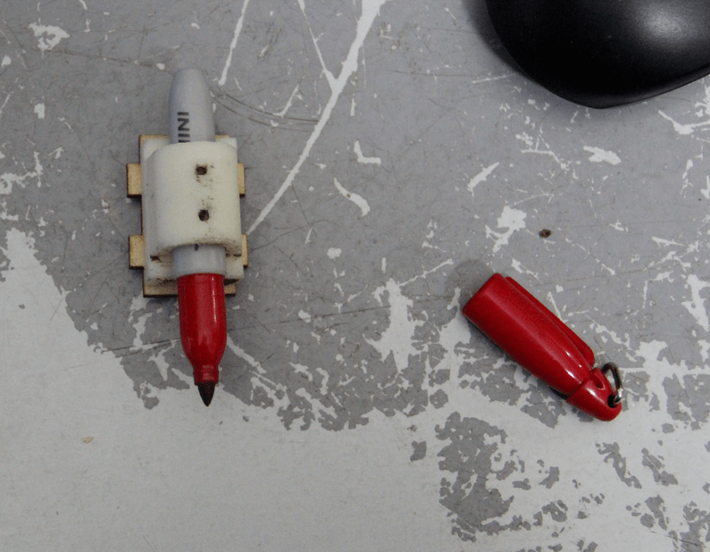
We planned this arm to be used for multipurpose use like pick and place,plotter etc. So i designed a pen holder for it as an end effector in Rhinoceros. It is having two parts one is a 2D base part to fix into the head of the arm which made using craft wood and the second part is a 3D printed pen holder, actually i designed a pen holder exclusively for sharpie mini marker. The design and 3D printed parts are shown below. The right one is the 2D drawing of the base part and the left one is the 3D design of penholder.
After the design the base part was exported in .dxf format and cut using laser cutter. The 3d design of penholder was printed on Dimension SST1200es printer on ABS plastic both parts are shown below.
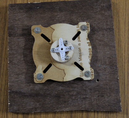
After assembling the side plates , the main servo has placed on the base, in order to assemble the base we require a thin ball bearing, that is not available locally, so we planned a bypass method to temporarily mounting the arm to the base, using the servo blades we mounted the arm to the base plate. The blade was made of plastic and it is not capable of holding the weight , so in between it is falling down. The base plate also mounted on the 12mm wooden sheet as shown in the picture.
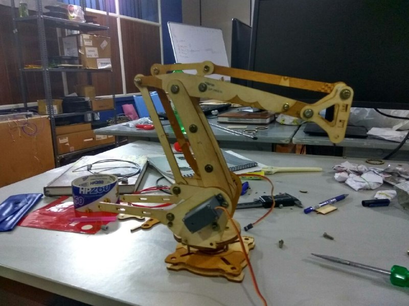
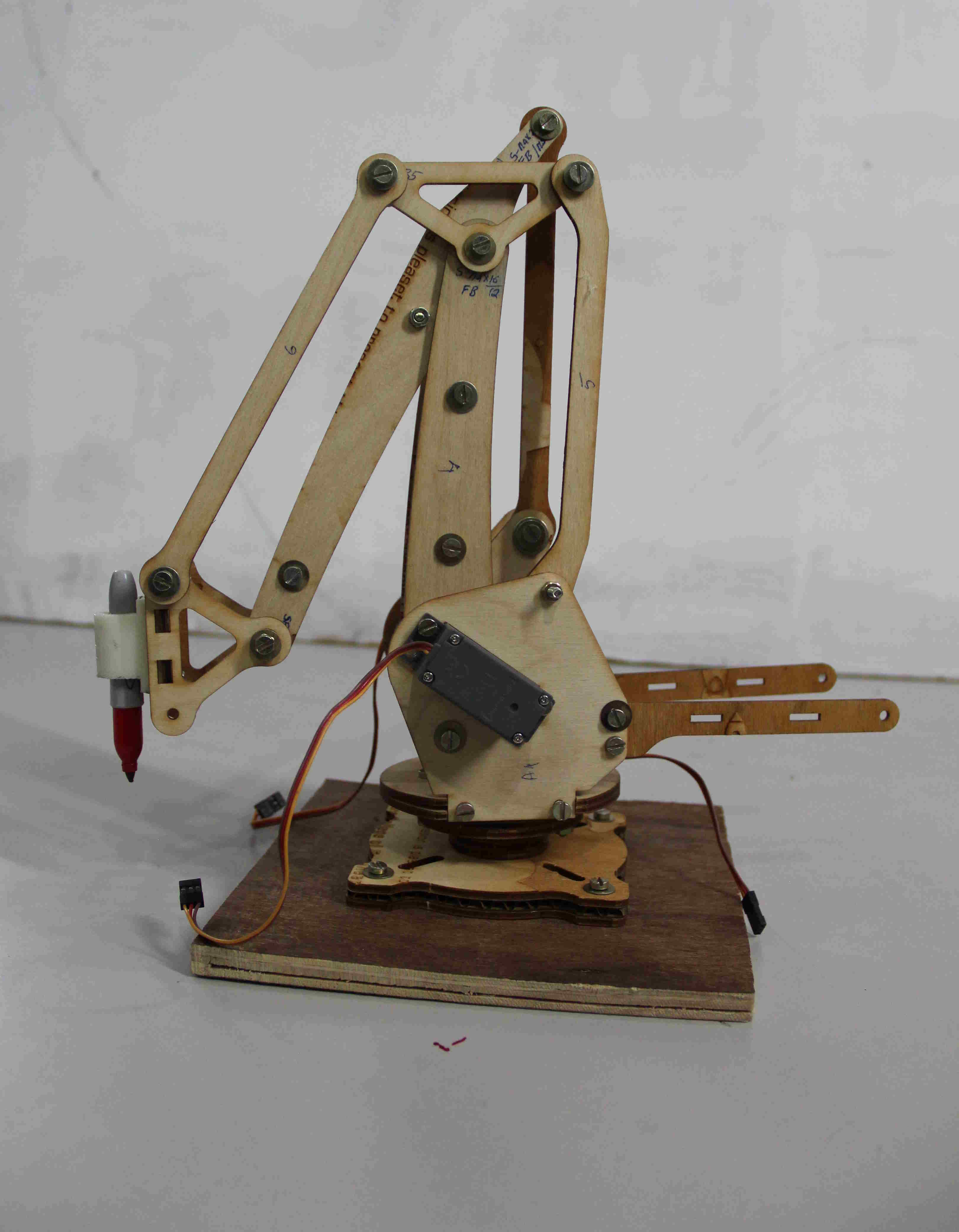
We had done some basic testing of the arm in three axis with the arduino board. Renjith has done the programming for moving each servos in particular angles, our main aim was to move the arm in all three directions. He written the program for moving the servos in arduino, Myself and Jithesh helped to test the arm. Programmed arduino and now the arm started moving but due to the lack of bearing base is slipping from the plastic blades,we require a bearing to mount the base to solve this issue, we have ordered for the bearing and expecting the earliest delivery . Mounted the Mini sharpie over the end effector and moved the arms and sketched some lines with the arm. The hero shot of our arm with my pen holder end effector is shown below.
Download my penholder design files (.zip)
The Video shown below is the working of the Fab Arm using Arduino board, it was a good experience for me to work with in a team to build such a machine and learned a lot of things from different peoples.
Quote of the Week
"Coming together is the beginning. Keeping together is progress. Working together is Success"
by Henry Ford