WEEK 8
EMBEDDED PROGRAMMING
ASSIGNMENT
- Read a microcontroller data sheet.
- Program your board to do something, with as many different programming languages and programming environments as possible.
- Optionally, experiment with other architectures.
Preperation
In this week we have to program the echo hellow world, made in week6 to control the LED using a switch. Refreshed the lessons from week6 and gone through the datasheet of Attiny44 and through the tutorials of embedded C and basics of AVR architectures.
tinyAVR Microcontrollers
Atmel tiny category of microcontrollers are optimized for applications that require performance,power efficiency and easy of use. All tinyAVR devices are based on the same architecture and compatible with other AVR devices.To know more about the features of the tiny category click here
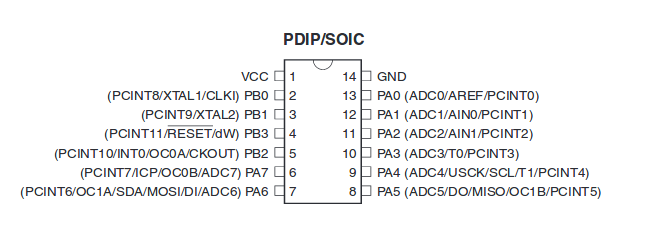
Attiny44A
Attiny 44A is the high performance 8bit AVR RISC based architecture microcontroller by Microchip It is having 4KB ISP flash memory,256 Byte EEPROM, 256B SRAM,12 general purpose I/O lines, 32 general purpose registers,an 8 bit timer/counter with two PWM channels,a 16-bit timer/counter with two PWM channels, internal and external interrupts, an 8-channel 10-bit A/D converter, programmable gain stage (1x, 20x) for 12 differential ADC channel pairs, programmable watchdog timer with internal oscillator, internal calibrated oscillator, and four software selectable power saving modes. The device operates between 1.8-5.5 volts. More detailed about each is described in the datasheet of ATtiny44A
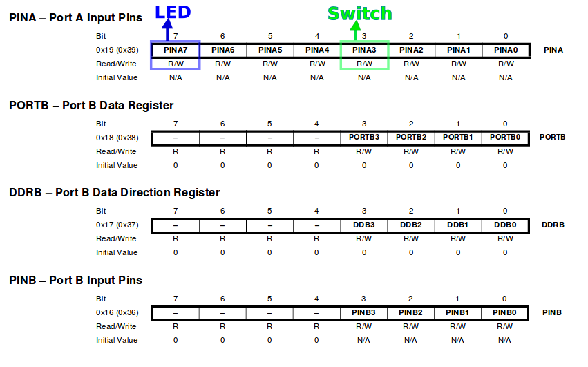
I had gone through the datasheet , it is difficult to understand all the things so i have identified those portions which is required for programming my echo hello world board. Since i have connected the switch and LED in Port A, here i am copying the deatiled structure of PORT A from the datasheet.
My Echo hellow world Board
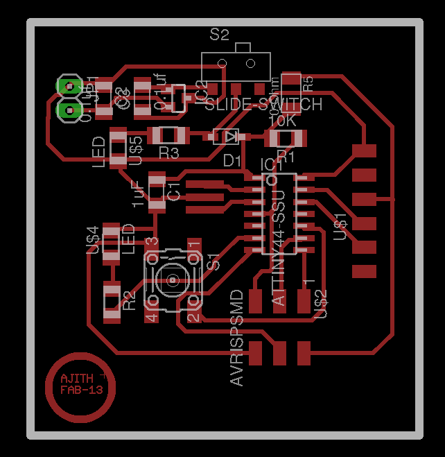
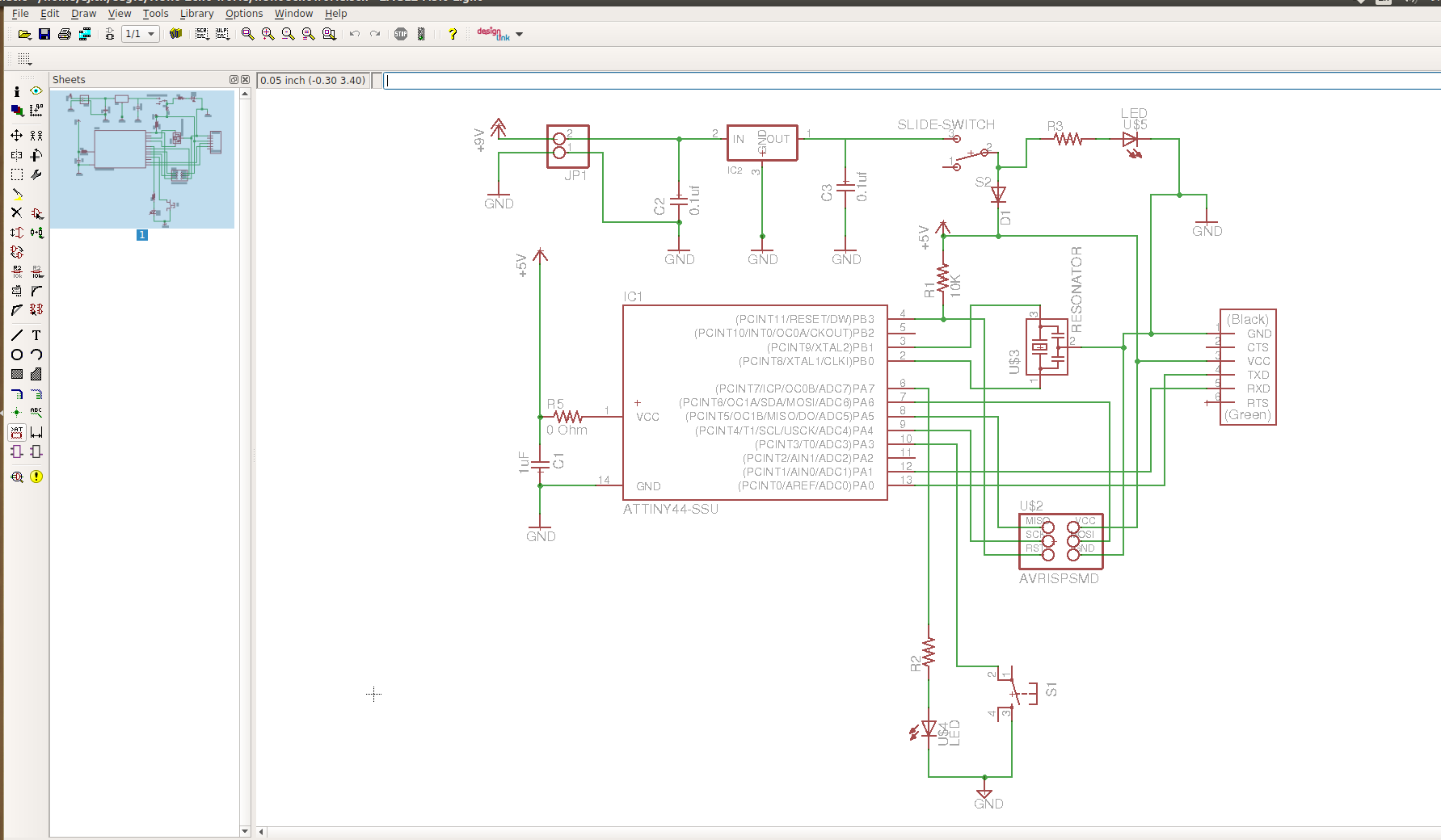
Before starting programming i have gone through the schematic of my board from Week6, Here i am copying the schematic sketch of my board with its position diagram. My board is having a button connected in Port A; PA3 and a Blue LED is connected on the PortA:PA7. Some more additional circuits are also their to operate the board using battery. The detailed documentation is given in my Week6-Electronics Design documentation.
Programming in AVR-GCC
I. LED Blinking (C Program)
First we have to check the board is working or not , last week i have tested the board using Neils echo hellow world program. Our Instructors Mr. Yadu & Mr. Vishnu
given introduction to the programming lanuages and about C programming language. Based on the lecture, I followed the same procedures to write the program. The program can be written in IDE's,
there are different varieties of IDE are available, I have used Atom as IDE. First i written a program
to blink the LED in atom and saved the file with .c extension. In this program written data direction register DDRA as "0XFF", means all the pins in Port A is configured as output ports. Then simply written logic 1 to the PortA pin PA3
with a delay of 100ms and agian written logic 0 to Pin PA3 to turn the LED OFF. In summary the LED will glow with a time delay of 100ms. The program and its description are given below.
LED Blinking Program
#define F_CPU 20000000		// defining CPU speed as 20MHz
#include < avr/io.h>		// Importing avr/io library
#include < util/delay.h>	//Importing delay library
int main(void)
{
DDRA=0XFF;			// Set data direction register to 0b11111111
while(1)
{
PORTA|=(0b10000000);		// Set PortA pin PA3 as logic high
_delay_ms(100);			// Setting a delay of 100ms
PORTA&=(!(0b00000000));		// Set PortA pin PA3 as logic low
_delay_ms(100);			// Setting a delay of 100ms
}
}
Testing the Board
This program is written in embedded C programming language. Actually the microcontollers will understand mechine level languages(binary), it is a low level language and hard
to understand, that's why we are using highlevel languages like "C". The programs will be written in C language and saved with extension ".c". Inorder to run this program on microcontroller we may need to conver the high level langauges to low level language.
Inorder to convert high level language to machine level language a Compilers/ Interpreters
is required. These two are having differences, we are using compilers to convert our C program to machine level language. The compiler used here is "AVR-GNU Compiler Collection"(AVR-GCC), GCC
supports C-code compilation, some debugging may be required while compiling, once you compiled successfully we will get a ".hex" file , that is the machine level code equivalent to our C program.
Next we have to flash the program into the microcontroller, for that we require AVRDUDE - AVR Downloader Uploader - is a program for downloading and uploading the on-chip memories of Atmel’s
AVR microcontrollers. It can program the Flash and EEPROM, and where supported by the serial programming protocol, it can program fuse and lock bits. Using Avrdude we can fuse the microcontrollers
with the help of a programmer. Avr dude supports different programmers, here i used my Fab ISP as the programmer.
Inorder to compile in avr-gcc and flash the program on attiny44, we may need to run certain commands from the terminal. One of our instructor, Mr.Yadu has developed one User Interface in python
language for easy compiling and flashing, it's called Compflash. Its available in the githublink, Compflash. I just cloned it in my
PC. It requires certain dependancies, you can install it in your PC using commands. Once cloned,open terminal from the cloned directory, then type python compfalsh.py. It will open
the GUI of comp flash like this.
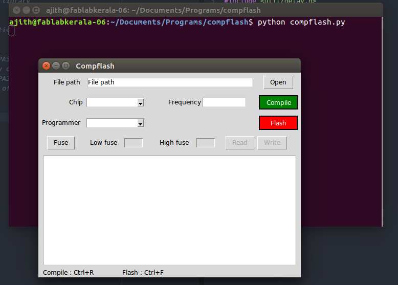
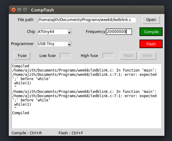
Next select the file from the directories, select chip,its frequency,and the programmer. I have selected selected my file from the folder, selected chip as ATtiny44
,frequency as 20MHz and programmer as USB Tiny. Then i pressed the compile button, at first some syntax errors were there so it showed the error, later i corrected the program and compiled
once again and this time it successfully compiled and is shown below.
Next I flashed the code into the microcontroller using the flash button, the LED starts glowing, you can check the working of the LED, Actually in the program i have given a delay of 100ms if it is not there,
you can click the Fuse button from the compflash and first read the fuse value, if it is not correct change it with the correct one and flash again. My output is showed below.
Download My program file (.zip)
II. LED control using switch (C Program)
My echo hellow world is actually meant for contolling an LED using a switch button. In the previous testing i have confirmed the working of LED, then i written the program to turn ON and OFF the LED using the switch. When the button is pressed the LED will glow and while releasing the button, the LED must be turned OFF. Started writing the code in C language using Atom IDE.
LED Control using Switch
#define F_CPU 20000000 		// defining CPU speed as 20MHz
#include < avr/io.h>		// Importing avr/io library
#include < util/delay.h>	//Importing delay library
int main(void)
{
DDRA=0xF7;			//Setting the DDRA register with 0b11110111(enabling PA3 as input)
PORTA|=(0b00001000);		// Pulling Port PA3 to logic High(Switch)
PORTA&=(0b01111111);		// Setting the LED (connected to PA7) permenantly OFF
while(1)
{
if (!(PINA & (1<<3)))		 // Checking for Switch press
 {
PORTA|=(0b10000000);		// Writing PortA- pin PA7 to logic high (LED ON )
}
else
{
PORTA&=(0b00001000);		//Set PortA pin PA3 as logic high(pulling up)
}
}
}
First, I enabled the PortA pin PA3 as input port by writing the hex value of 0xF7 equivalent to binary 11110111 because
i have connected switch in PA3; that is an input. In the next step i have permenantly turned OFF the LED(PA7) why because if we leave it as such, the pin may be in floating codition
and LED will be turned ON/OFF in between. Next step checked the condition for a switch press, for that If loop is used here, in this the Port A data will be read and logiaclly ANDed with XXXX1XXX
then taken the compliment of it, if a key press is detected the codition will be Logic high and program enters into the loop and wirte logic high to PortA PA7 so that the LED will be turned ON.
otherwise the LED will be in OFF state and pulling up the PortA-PA3.
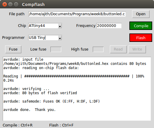
The above showed image is the compiling and fusing stage of the program into my board using compflash and the out put is showed below. It doesn't showed any compilation errors and worked fine.
Download My LED control with switch program file (.zip)
III. LED control with switch count (C Program)
In this section i tried a different control logic that the LED will glow according to the number of switch press it detected. I have given a count of 5 to enable the LED , when five switch presses will be detected the LED will turned ON. My program is shown below, myself and Mr. Renjith to gather done the programming. Program is shown below.
						 LED Control with switch count

#define F_CPU 20000000		// defining CPU speed as 20MHz
#include< avr/io.h>		//Importing avr/io library
#include< util/delay.h>		//Importing delay library
int fun();			//Intitialising a function called "fun"
void press();			//Intitialising a function called "press"
int a;				//Intitialising a variable "a"
int main(void)
{

DDRA=0xF7;			//Setting the DDRA register with 0b11110111(enabling PA3 as input)
PORTA|=(0b00001000);		// Pulling Port PA3 to logic High(Switch)
PORTA&=(0b01111111);		// Setting the LED (connected to PA7) permenantly OFF
while(1)
{
if (!(PINA & (1<<3)))		// Checking for Switch press
 {press();			// Function "press" will be executed
 }
else
{
PORTA&=(0b00001000);		//Set PortA pin PA3 as logic high
}
}
}
int fun()
{
  static int i=0;		//set the initial value of i=0
  i=i+1;			//value of i=i+1
 i=i%5;				//comparing the number of switch press with a count value of 5
  return i;			//returens the value of i
}

void press()
{
_delay_ms(500);			//providing a delay of 500ms
if (!(PINA & (1<<3)))		// Checking for Switch press
_delay_ms(500);			//providing a delay of 500ms
if ((PINA & (1<<3)))		// Checking for Switch release

a=fun();			//calling the function "fun" and returning the value to variable "a"
if(a%5==0)			//checking the count
{
  PORTA|=(0b10000000);		// Turn the LED ON when five switch press detected
_delay_ms(500);			//providing a delay of 500ms
PORTA|=(0b00001000);		//Set PortA pin PA3 as logic high
}
}
Its compilation and fusing steps are same as like previous programs,many errors were there during the coplilation ,some how i corrected it and completed the compilation and fused the hex file to my board, but at first it didn't worked correct, after analysis it is found that initially we had given the delay as 100ms it was not sufficient, So we increased the delay value to 500ms . This time it worked perfectly as shown in the below video.
Download My LED control with count program file (.zip)
Interrupt Programming
What are interrupts?
Interrupts are basically events that require immediate attention by the microcontroller. When an interrupt event occurs the microcontroller pause its current task and attend to the interrupt by executing an Interrupt Service Routine (ISR) at the end of the ISR the microcontroller returns to the task it had pause and continue its normal operations. In order for the microcontroller to respond to an interrupt event the interrupt feature of the microcontroller must be enabled along with the specific interrupt. This is done by setting the Global Interrupt Enabled bit and the Interrupt Enable bit of the specific interrupt.
Interrupt Service Routine or Interrupt Handler
An Interrupt Service Routine (ISR) or Interrupt Handler is a piece of code that should be execute when an interrupt is triggered. Usually each enabled interrupt has its own ISR. In AVR assembly language each ISR MUST end with the RETI instruction which indicates the end of the ISR.
Interrupt Flags and Enabled bits
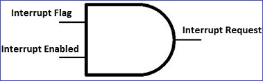
Each interrupt is associated with two (2) bits, an Interrupt Flag Bit and an Interrupt Enabled Bit. These bits are located in the I/O registers associated with the specific interrupt:
- The interrupt flag bit is set whenever the interrupt event occur, whether or not the interrupt is enabled
- The interrupt enabled bit is used to enable or disable a specific interrupt. Basically is tells the microcontroller whether or not it should respond to the interrupt if it is triggered.
In summary basically both the Interrupt Flag and the Interrupt Enabled are required for an interrupt request to be generated as shown in the figure below.
Global Interrupt Enabled Bit
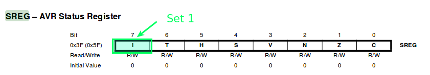
Apart from the enabled bits for the specific interrupts the global interrupt enabled bit MUST be enabled for interrupts to be activated in the microcontoller. For the AVR 8-bits microcontroller this bit is located in the Status I/O Register (SREG). The Global Interrupt Enabled is bit 7, the I bit, in the SREG.

The deatiled documentation is available in AVR Tutorials, It is more informative and usefull for beginners.
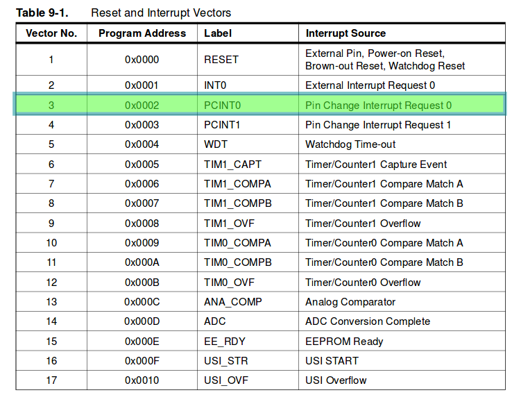
I have gone through the datasheet and identified the registers that to be used for interrupt programming, the first one is the interrupt vector table for Attiny 24A/44A/84A.
I heve used PCINT0 Pinchnge interrupt vector 0. when a pin change occurs on the Port the ISR will be called.
SREG- Status I/O register
Status register in Attiny44 is a 8bit register shown below. In this Bit7 is global iterrupt enable bit , we have to set it to 1 for the interrupts to be enabled. If it is cleared,none of the interrupts are enabled.
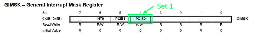
GIMSK – General Interrupt Mask Register
GIMSK is a 8 bit Interrupt mask register out of which 3 bits are used as shown below, In this register we have to set PCIE0: Pin Change Interrupt Enable 0 to 1. When the PICE0 & the I th bit (bit7) of SREG are set to 1 ;any change on any enabled PCINT[7:0] pin will cause an interrupt.The corresponding interrupt of Pin Change Interrupt Request is executed from the PCINT0 Interrupt Vector.
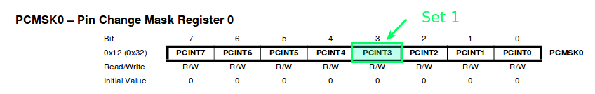
PCMSK -Pin Change Mask Register
In Attiny44 there are two 8 bit pin change mask registers are there, total 12 bits are used out of 16 bits. These are named as PCINT0 to PCINT11, PCINT0 to PCINT7 (total 8 bits)
in one register called PCMSK0 and the other PCINT8 to PCINT11 in PCMSK1 register. In my case , button is connected to PCINT3(PA3) so i have to consider PCMSK0 registerand
set 1 to PCINT3(bit3)
Button Interrupt program
Button Interrupt program
#define F_CPU 20000000 #include#include #include ISR(PCINT0_vect) { //Pin Change Interrupt Request 0 if(bit_is_clear(PINA, PA3)) { // this is true when a button is pressed PORTA |= (1 << PA7); //turn LED on } if(bit_is_set(PINA, PA3)) { // this will happen when the button is released PORTA &= ~(1 << PA7); //turn LED off } } int main(void) { DDRA=0xF7; // PA3 pin is made as input(0b11110111) PORTA|=0x08; //PA3=1 means internal pull up(0b00001000)in order to avoid floating condition GIMSK |= (1 << PCIE0); // enable pin change interrupt 0 PCMSK0 |= (1 << PA3); // only for the button sei(); // enable interrupts globally while(1) ; return 0; }
In this program the DDRA and PORTA registered are set like the previous program. DDRA PA3 is made as input and pulled up the input. Enabled the GIMSk,PCMSK0 registers and enabled the interrupts globally
by enabling sei(). When a pin change occurs the the program will jump to the ISR and executes the functions below the ISR, In this the button press is detected using the macros function.
bit_is_set(sfr,bit), bit_is_clear(sfr,bit)is a macro it will test whether bit bit in IO register sfr(special function register) is set or clear. When the button is pressed the interrupt will get
enabled and the LED will glow. Compliled and the out put is shown below.
Download interrupt program file (.zip)
Programming using Arduino
What is Arduino?
Arduino is an open-source platform used for building electronics projects. Arduino consists of both a physical programmable circuit board (often referred to as a microcontroller) and a piece of software, or IDE (Integrated Development Environment) that runs on your computer, used to write and upload computer code to the physical board. There are a large collection of tutorials are available on Arduino, out of which ,I found the following tutorial is good to know more about Arduino.
Sparkfun tutorial Installing Arduino IDE in Linux is simple follow these steps to install Arduino. I planned to programm my board using Fab ISP through Arduino IDE. Arduino IDE by deafult supports all arduino boards, inoreder to work with external boards we have to first add the board support to arduino. I followed the following steps. After installing the support for Attiny catefory , from the tools menu i have given the following settings to program my board.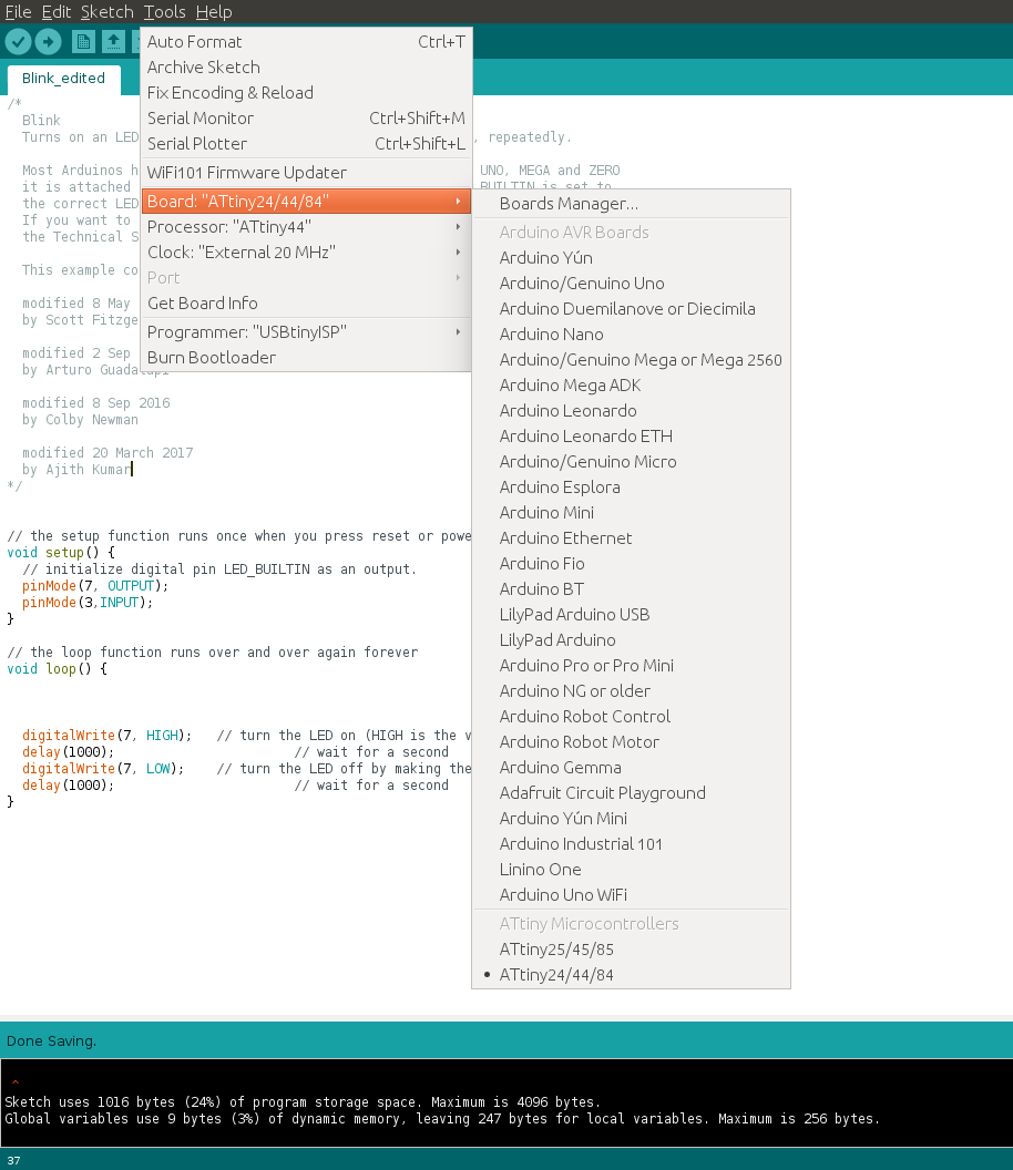
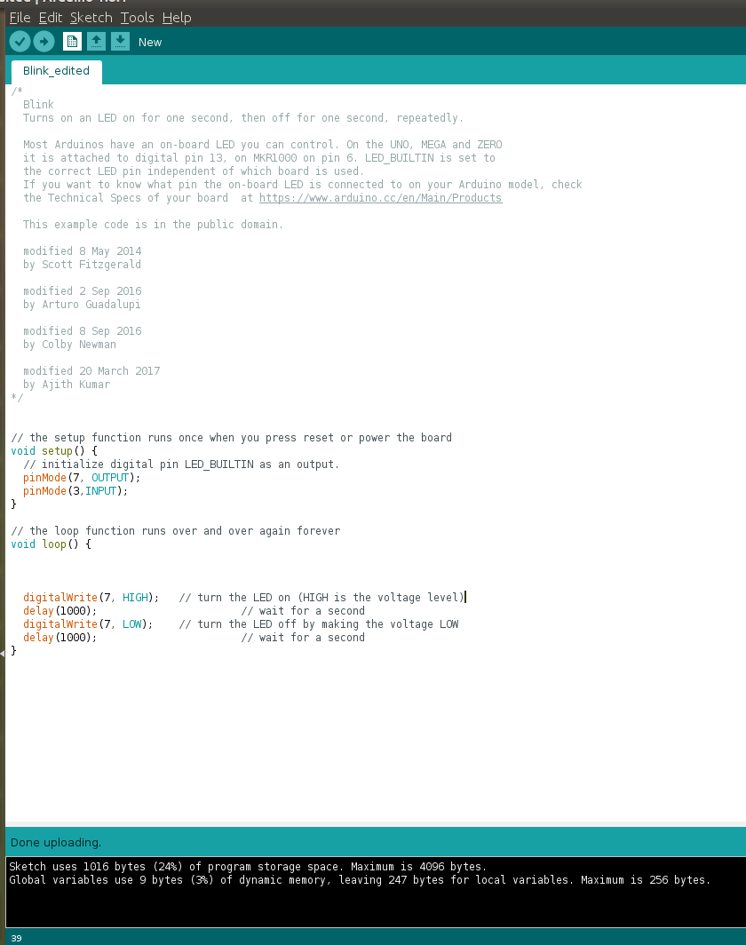
I. LED Blinking Program(Arduino)
I edited the LED blinking sample program from arduino example programs. Given the LED and switch pins according to my board design. It is very simple to use, edited
the program and saved with an extension .ino. Programs written in Arduino are called Sketches and are saved under extension .ino. After this we can compile the program
from Sketch menu or Short keyCtrl+R or tick button from the UI, for uploading the code to our board we can use short key Cntrl+U or upload
option from Sketch menu or right arrow button form the UI.
Done compiling and uploading of the program to my boar and the LED blinked with a delay of 1seconds. The prgram and the output is shown below.
In this i have tried my battery mode operation, programmed the board and confirmed the working of it, after that i changed my ISP connection and connected 9V battery using battery snap and truned in to "battery mode". Now by board started working in Battery mode. The out put is shown in the video.
Download My program file (.zip)
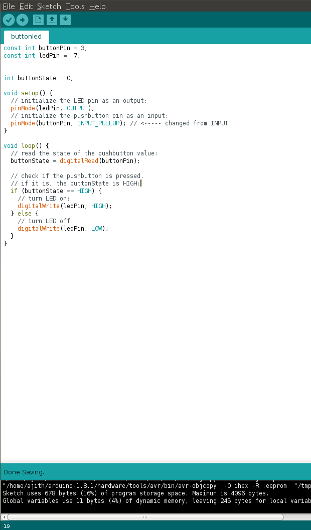
II. Button LED
Next I have tried the program of button LED, In this this when a button is pressed the LED will glow. I have done compilation and fuse using the arduino and tested the board. The logic of the program is same as the program i have written using C program. The program is shown below, its worked for my board and here am not putting the output of the program.
Download My program file (.zip)
III. LED Counter
This is the other program i tried with arduino,similar to the LED control with switch count program in C program. This will count will start from counting 1, 2, 3 etc.If you press the button first,LED will glow for a single time, next time press it will glow 2 times, like this it will continue. The program and the output is shown in the picture/video .
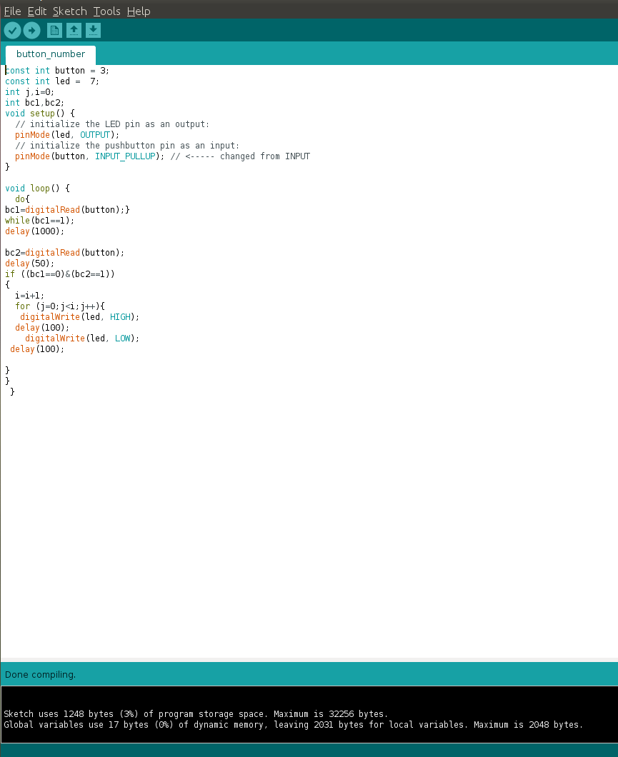
The output of the program is shown below, in this the LED will count from 1 to 4 for each button press
Download My program file (.zip)
What questions do you have? What would you like to learn more about?
In this week i have gone through the datasheet of Attiny44 and learned about AVR architectures, In my college days i have studied studied about AVR but never worked and now i am happy that i got an opprtunity to work with it. I had good working experience in with 8085 and 8086 microprossessors in Assembly level language , when i approached these latest architecture processors i got the real advantage of the microcontroller units than micro processors. The different modes of operation and special functions and its setup are confusing me a lot, Need to study in depth about the architecture. But i need to go further on higher processors like Atmega328 and Arm architectures why beacuse i am having very much interested in working with processors.
Conclusion
In this week ,I have tried C programming language and Arduino language and i personally satisfied with C programming. Arduino is very simple and can program easily,but to program with C requires little knowledge in C. The main difference between the two are in the compiled hex file sizes. In the below chart i have compared the sizes of my programs in AVR-GCC and Arduino.
| Program(hexfiles) | AVR-GCC | Arduino |
|---|---|---|
| LEDblink | 316 bytes | 2832 bytes(2.8kB) |
| ButtonLED | 238 bytes | 1928 bytes(1.9kB) |
| LEDcounter | - | 3466 bytes(3.5kB) |
| LEDbuttoncount | 852 bytes | - |