WEEK 13
INPUT DEVICES
ASSIGNMENT
- Measure something: add a sensor to a microcontroller board that you have designed and read it.
Preperation
This week assignmemnt is to interface microcontroller with input devices like switches, keyboards,PIR sensors,temp & humidity sensors etc. Gone through all the basics of different sensors and their workings based on that i decided to make a temperature and humidity display system for our lab.
FTH Display
FTH Display is the Fab Temperature and Humidity Display module i am planning to make for our lab. Its main unit is a temperature and humidity sensor called DHT11, which is a diital sensor used for sensing the temperature and humidity.
DHT11
DHT11 is a Temperature & Humidity Sensor and it includes a resistive type humidity measurement component and an NTC temperature measurement component.The out put of the sensor unit is a caliberated digital output can be read by a microcontroller and displayed using LCD/OLED display. It is having asingle wire serial interface which increases easy integration. There are different manufacturers making DHT11 sensor and is having different pinouts. I used ASONG DHT11 sensor purchased from aliexpress. Range and accuracy of DHT11 sensor is shown below.
Relative humidity
- Resolution: 16Bit
- Repeatability: ± 1% RH
- Accuracy: At 25°C ±5% RH
- Response time: 1 / e (63%) of 25°C 6s 1m / s air 6s
- Hysteresis: <± 0.3% RH
Temperature
- Resolution: 16Bit
- Repeatability: ±0.2°C
- Range: At 25°C ± 2 °C
- Response time: 1 / e (63%) 10S
- Power supply: DC 3.5~5.5V
- Supply Current: measurement 0.3mA standby 60μ
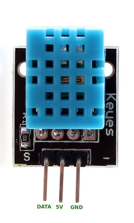
The breakout board of DHT11 pinout is shown below. It is having only three pinouts VCC,GND and a Data line out of this VCC we can connect it to 5V supply of the board and GND to our board GND.
Interfacing DHT11 with Attiny44
This week i am using attiny44 breakout board to interface with the DHT11 sensor. The interfacing diagram drawn in draw.io is shown below, In that VCC and GND we can connect to our board. If we are using a connection cable less than 20 meters , a 5K ohm pullup resistor is recommended and for greater than 20 meters the value of this pullup resistor can be trimmed. Here i used a 5K ohm resistor as pullup resistor.
FTH Display Board design(Double side PCB)
FTH Display board is designed with Attiny44 micro controller. Actually my plan is to make a breakout board of attiny44 where all the pinouts were terminated to the header pins so that i can easily connect multiple sensors by just connecting the header pins. Regulated power supply module was added to operate the board using 9V battery.
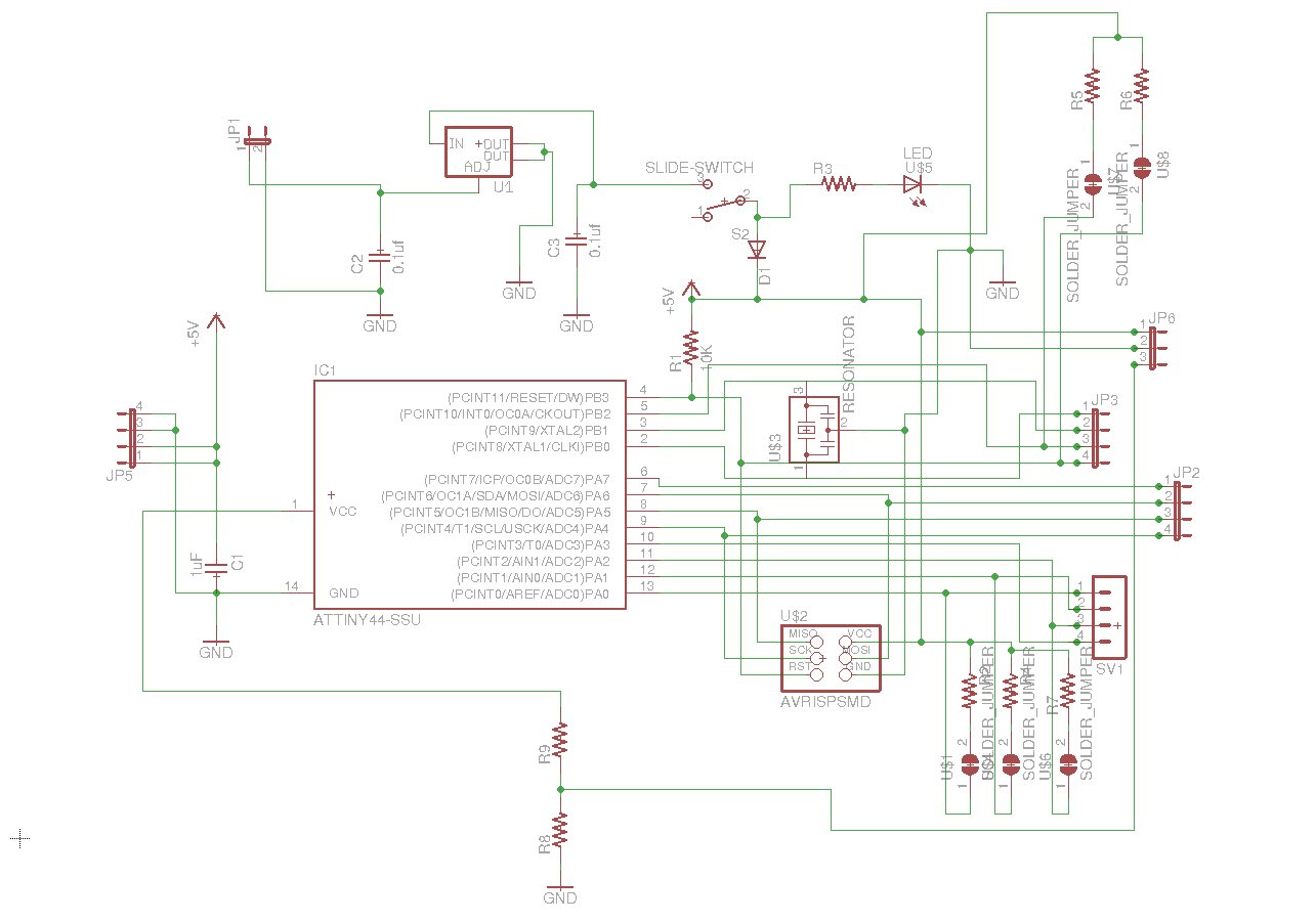
I started designing the board in eagle cad software, from the beginning of the academy i wish to make a double sided pcb. So this week i thought to make a double side pcb. All the componenets were added into the schematic from the library and the circuit interconnections were made and done the ERC checks, corrected the issues. The schematic of my board is shown below.
After completing the schematic i switched to board and first set the design rules for the pcb. Then the componenets were arranged in the dimension space, some componenets were placed in the bottom layer and given auoto routing option. You can place the componenets in the bottom layer by selecting the componenet and click the mirror option. Autorouting gave only 90% routing and the rest of the unrouted lines routed manually. The connections from the top to bottom layer is done through vias. The top and bottom position diagram of FTH board is shown below.
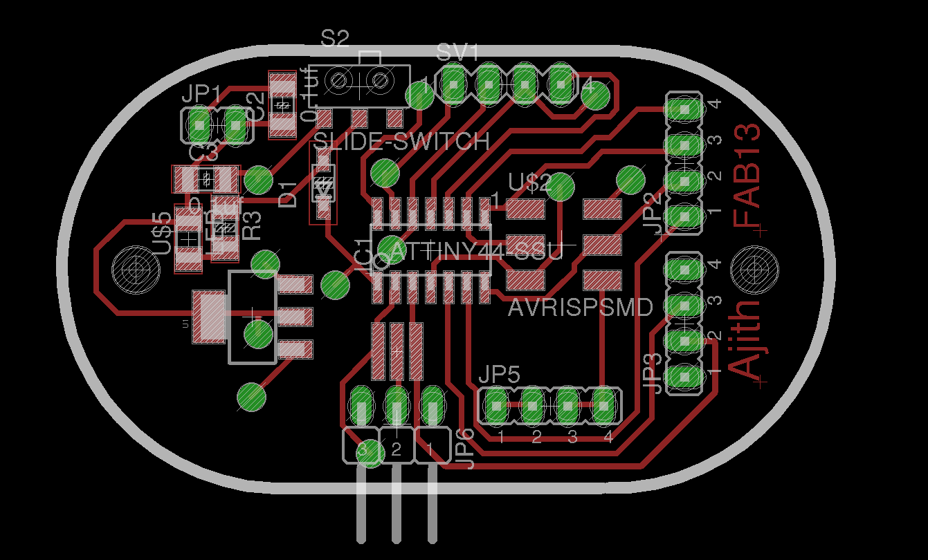
FTH board Top layer
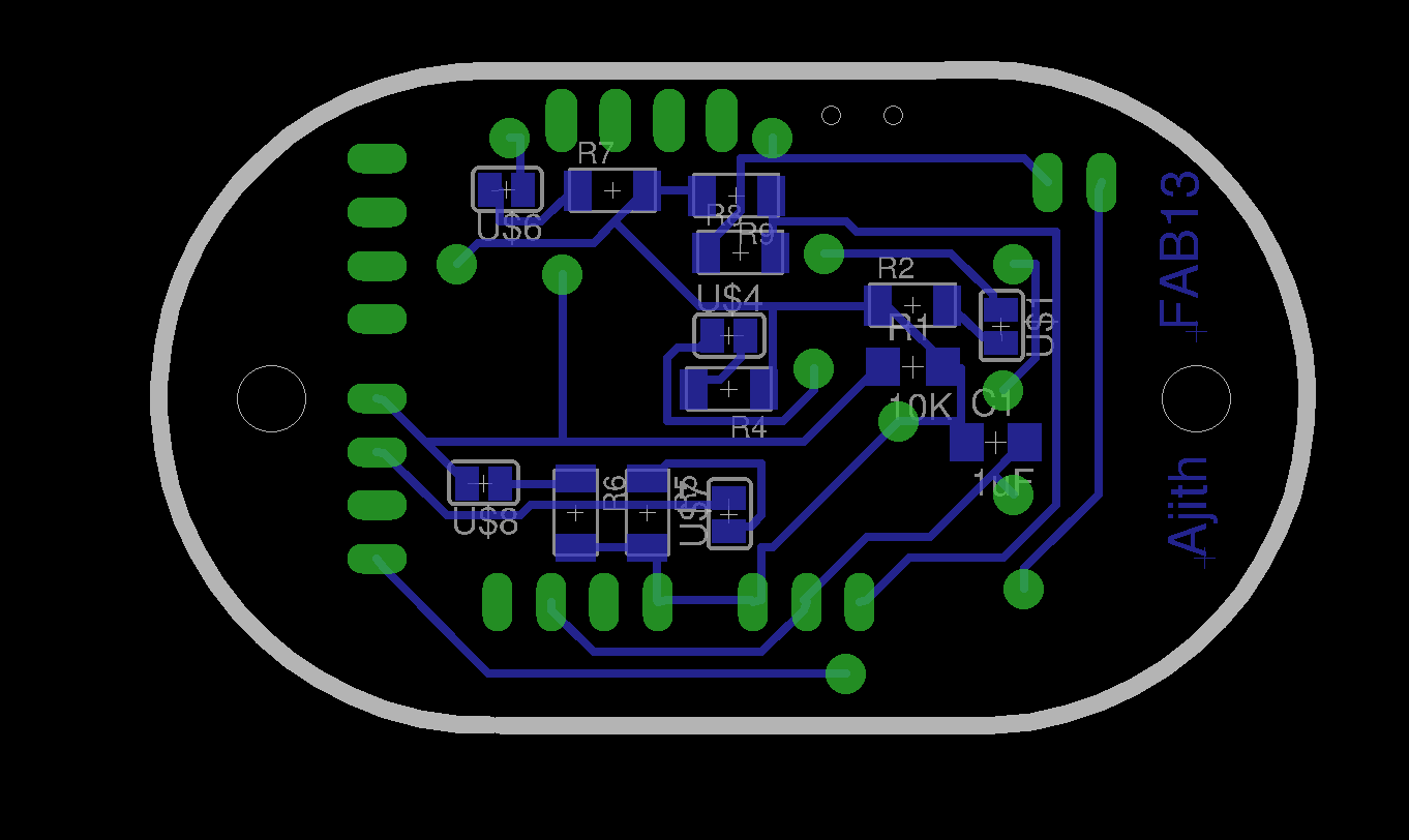
FTH board bottom layer (flipped horizontally)
Completed the routing and then to process the pcb in modela we require the layer diagrams in .png format for that from the board layout exported the top layer and bottom layer traces for milling the traces. Next cutout the board and drilling the vias file is exported to png format. the milling traces and cutout board png images are shown below.
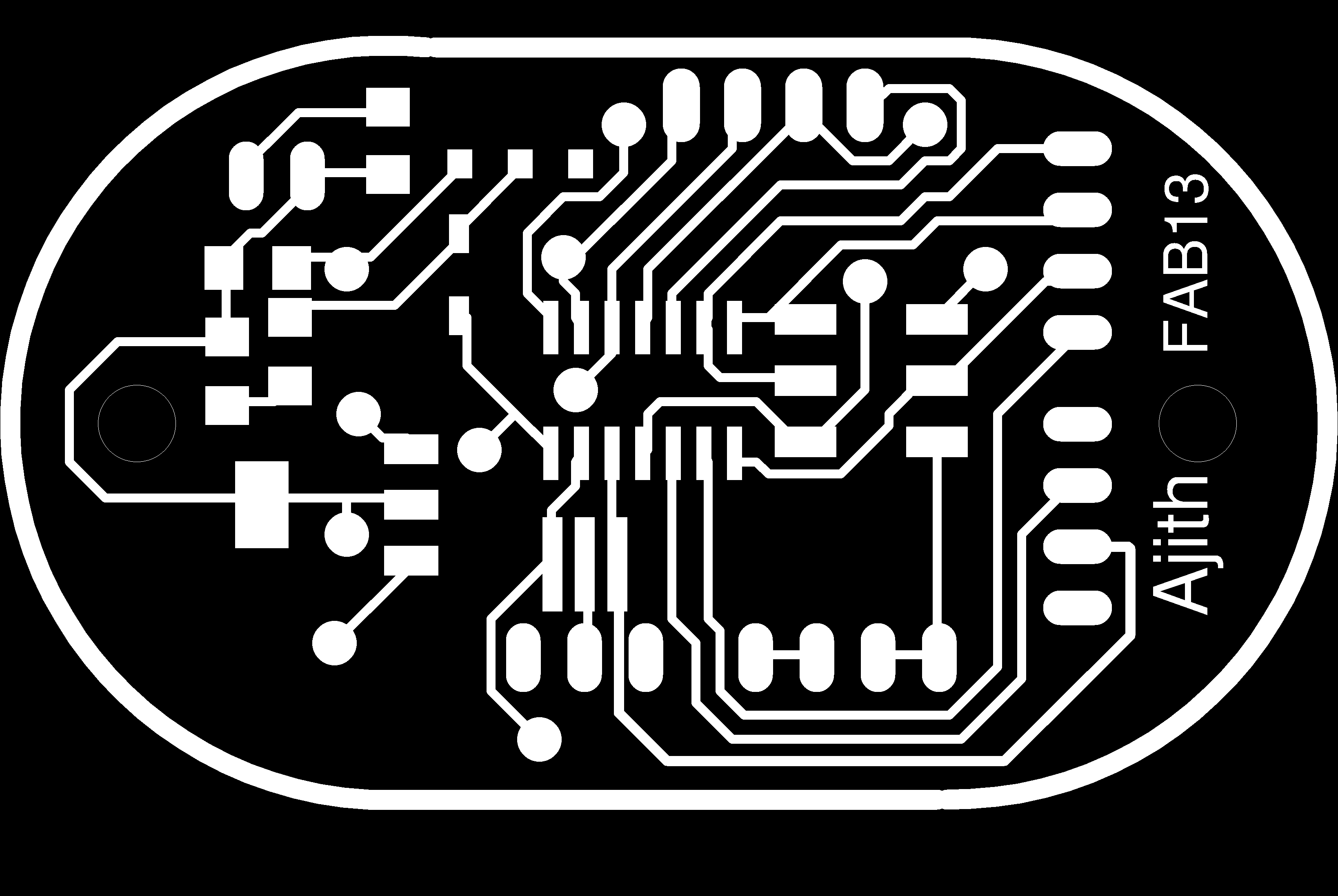
FTH board top layer mill traces
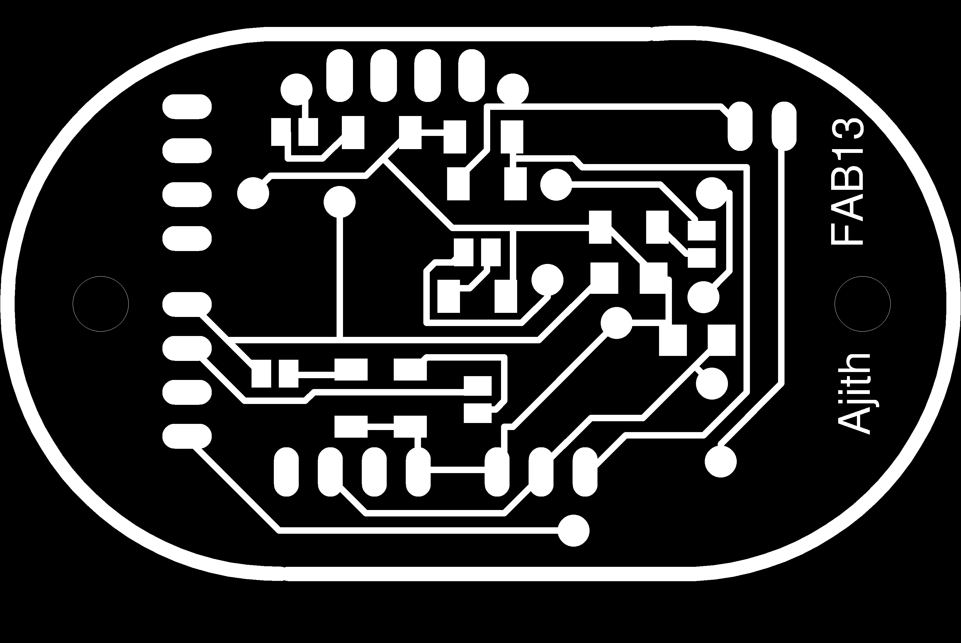
FTH board bottom layer mill traces(flipped horizontally)
Making Double side pcb in Modela
Inoreder to process the double sided pcb in modela, i have done the following steps. You can follow those steps.
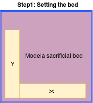
Step 1
First we have to place a L plate on the top of the sacrificial layer. Here i used two pieces of pcbs and sticked it perfectly using the double sided tape as shown below. After that we have to do some testes on scrap materials. Ensure the two plates having 90 degree angle between them.
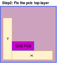
Step 2
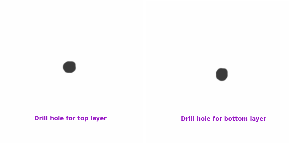
In this step we can use a scrap double sided pcb sheet and stick it correctly on the plates using double sided tape. Then using gimp i have made a small dot with approximately 1/32 mils and using 0.8mm bit drilled a hole with a depth of only 0.9mm where as the actual drill depth is 1.7mm.
The drill hole i have created in Gimp is shown below. The drill hole for the bottom layer is flipped horizontally and rotated 90 degree clock wise.
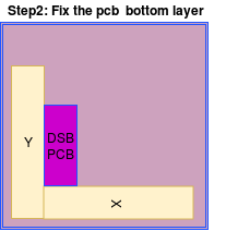
Step 3
Then i flipped the board horizontally and rotated it in 90 degrees and kept it on the bed without changing the origin. The same png file is also flipped horizontally and rotated 90 degree clock wise and again done the drilling process with o.9mm depth. Check wether the two holes drilled are having same alignment. If not we have to adjust the X & Y coordinates in fab modules. This is a trial method we have to do so many trials to findout the actual coordinates which exactly matches the two hole dimensions. Once you findout the coordinates note it down safe.
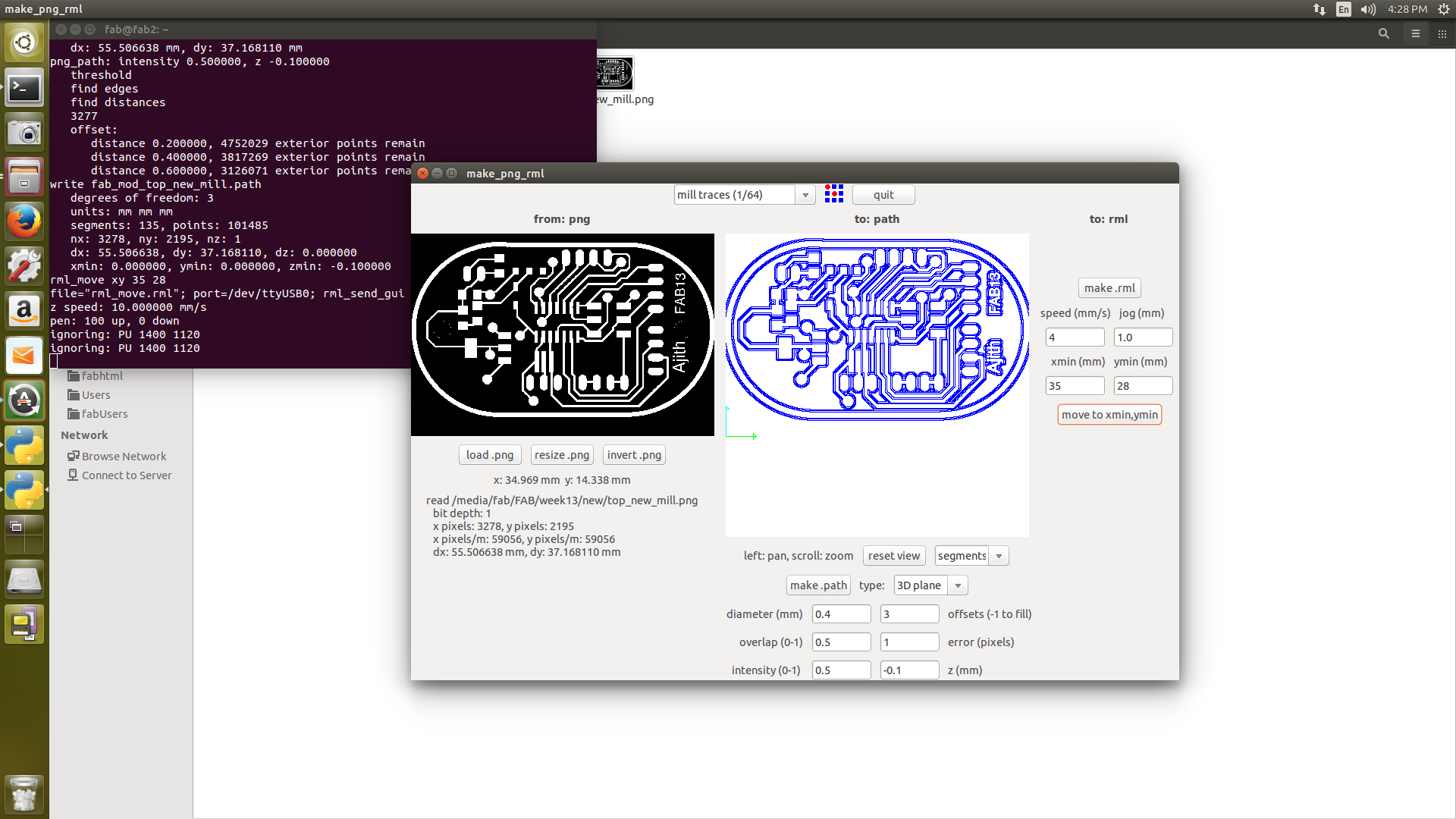
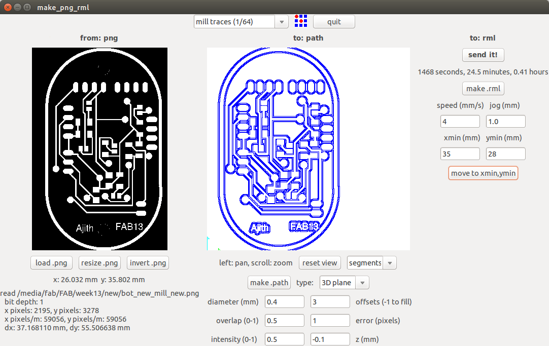
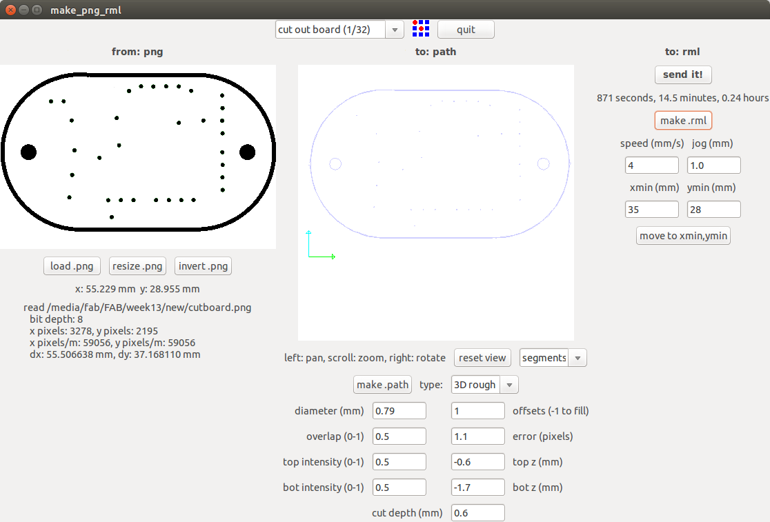
I have done all the steps mentioned above and done so many testing for finding out the coordinates. My coordinates where X=35,Y=28. Each profiles are processed in modela using fab modules. The machine setup details are not giving here, you can refer electronics production week assignment for more details. The first figure shows the top layer milling with 1/64 mil bit.
Drill holes and cutout board
Drilling the via holes and cutting out the board are same like the one we are following in single sided boards, here we have to keep the board in the origin that's all. The image shown below are the pcb cutout board profile in fab modules and i used 1/32 bit for drilling and cutting the box.
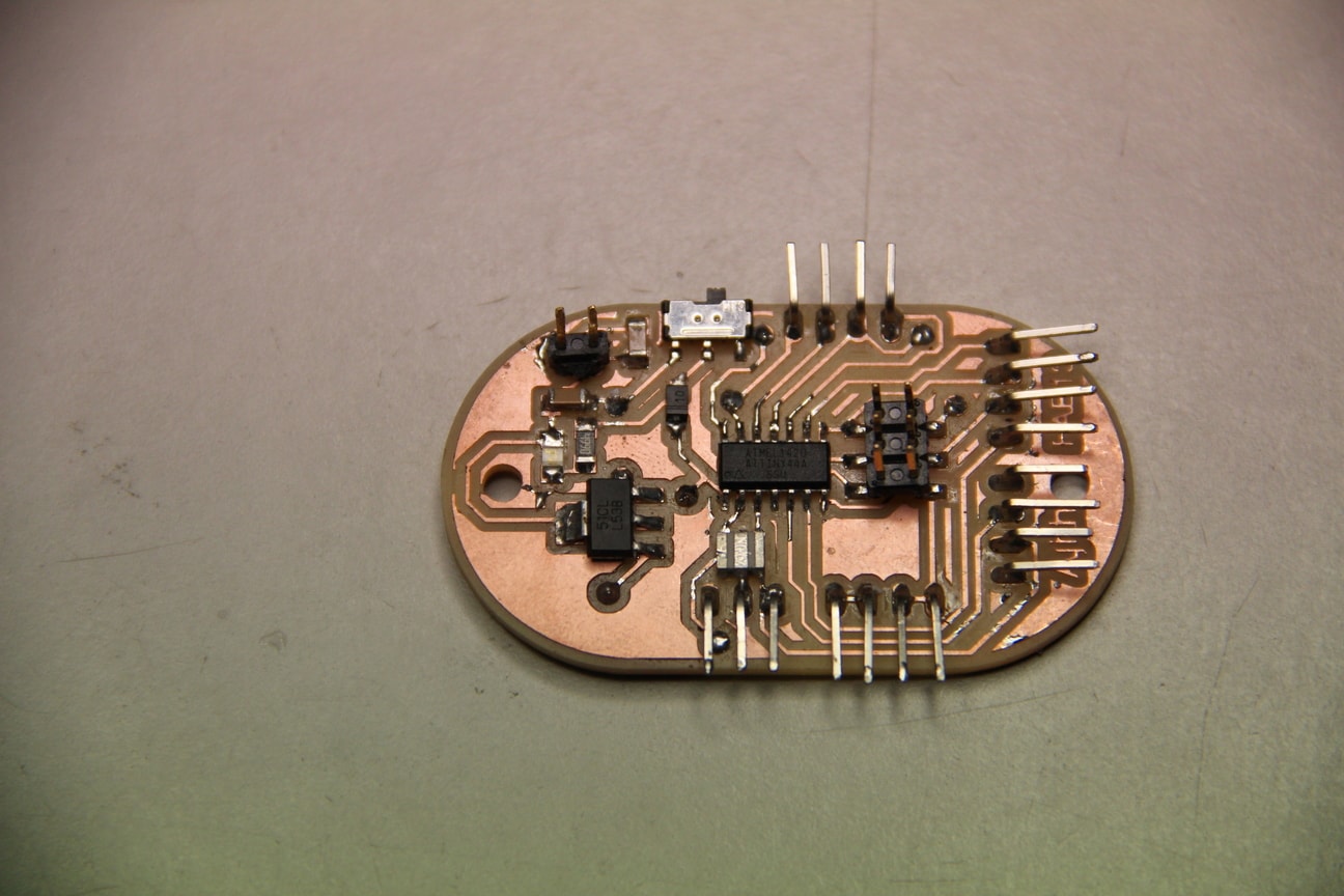
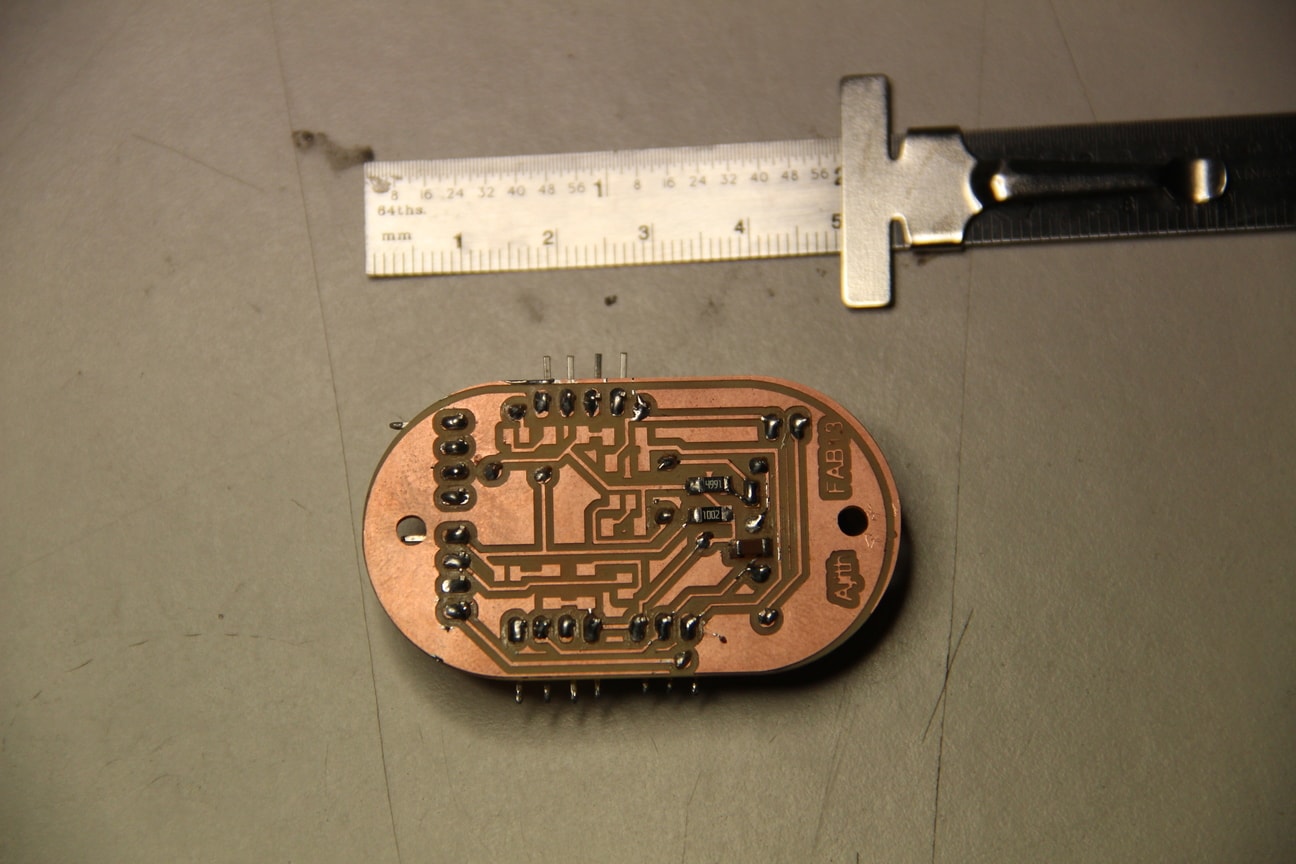
FTH board after soldering
After completing the milling the componenets required are collected from the inventory and started soldering. Here i am skipping the soldering steps. You can see my FTH board after the soldering. After soldering i verified the entire board for any shorts and other deviations.
Programming FTH Display board
Actually i planned to program the board to display the temperature and humidity readings in LCD module, as the first step to test the board i connected the fabisp board to it and programmed the board to blink an LED. There some problems i faced when i programmed it didn't programmed and showed error, later i found that some connections where shorted in near by tracks. I removed those tracks and programmed this time it worked successfully forgot to take the snaps.
In order to do serial communication with Attiny44 and PC , used FTDI cable for the communication. DHT11 data pin is connected to PA0 pin and Tx and Rx pin of FTDI connector is connected to PA1 and PA2 of the Attiny board. Then i have gone through Neil's hellow echo world program from the archieves, also refered some programs to interface the DHT11 sensor and combined those codes in Atom editor and tested, The code i edited is shown below.
FTH board programming
		Initialization and communication between MCU and DHT11
		/*
 * ATmega16_DHT11_Project_File.c
 *
 * http://www.electronicwings.com

 *modified by Ajith Kumar M G in Fab Academy2017
 *on 02/05/2017 for Attiny44
 */

#include <#avr/io.h>
#include <#util/delay.h>
#include <#avr/pgmspace.h>
#include <#stdlib.h>
#include <#stdio.h>

#define DHT11_PIN 0

#define output(directions,pin) (directions |= pin) // set port direction for output
#define set(port,pin) (port |= pin) // set port pin
#define clear(port,pin) (port &= (~pin)) // clear port pin
#define pin_test(pins,pin) (pins & pin) // test for port pin
#define bit_test(byte,bit) (byte & (1 << bit)) // test for bit set
#define bit_delay_time 8.5 // bit delay for 115200 with overhead
#define bit_delay() _delay_us(bit_delay_time) // RS232 bit delay

#define half_bit_delay() _delay_us(bit_delay_time/2) // RS232 half bit delay
#define char_delay() _delay_ms(10) // char delay

#define serial_port PORTA
#define serial_direction DDRA
#define serial_pins PINA
#define serial_pin_in (1 << PA1)
#define serial_pin_out (1 << PA2)
#define max_buffer 25
The entire code is too lengthy you can download the code from here and see the editing i made in the code to show the temperature and humidity values through FTDI. The programming logic is first initialising the serial communication, for this portion i have reffered Neils code echo hellow world code for communicating with the computer , then after defining the DHT11 interface pins the microcontroller sends start pulse to the sensor to make it low to high and receives the data from the sensor after receiving the response pulses, 40bit data is received by the MCU serially and it will be displayed. Done the programming and successfully compiled after some debuggings and my board worked successfully. Then i opened cutecom in terminal, showed the readings through the serial monitor. I programmed using compflash GUI and the out put video is shown below. It is showing the normal room temeprature of 25 degree and when i have kept EHT11 inside my hand the temperature is increasing. I have blown hot air from my mouth and it showed the increase in temeprature. I wanted to further change it to LCD diaplys so that i can mount it on the wall.