WEEK 3
COMPUTER CONTROLLED CUTTING
ASSIGNMENT
- Make lasercutter test part(s), varying slot dimensions using parametric functions, testing your laser kerf & cutting settings (group project)
- Cut something on the vinylcutter
- Design, make, and document a parametric press-fit construction kit, accounting for the lasercutter kerf, which can be assembled in multiple ways
Preperation
This week Assignment is to learn about laser cutting and vinyl cutting. We have a CO2 based Trotec speedy100 laser machine for cutting and engraving then a Roland Vinyl cutting machine Camm GX-24. I have gone through previous archieves of fab academy and figured out what to do in this week . Also , I have gone through some sites regarding hinges cutting and some interesting projects in laser cutting.
Laser Cutting
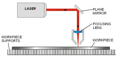
This week main aim is to design and cut a parametric press fit kit. We have a Trotech Speedy100 machine in our lab, It is a CO2 based Laser cutter. The Laser beam generted will be directed to the material. The sketch of a the laser cutter is shown below (got it from internet and edited).
Technical Specification of Speedy 100
The main features of the laser cutting machine is given below:
| Work area | 610 x 305 mm |
| Max. workpiece height | 170mm |
| Laser power - CO2 | 12 - 60 watts |
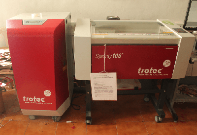
Laser cutter Speedy100 Machine
Parametric Pressfit Kit
A parametric press fit Kit is a fastening between two parts which is achieved by friction, after the parts are pushed together rather than by any other means of fastening. The tightness of fit is controlled by amount of interference; the allowance (planned difference from nominal size).Before doing the designs we have to find out the Kerf of the laser.
What is Kerf?
The laser burns away a portion of material when it cuts through. This is known as the laser kerf and ranges from 0.08mm to 1mm depending on the material type and other conditional factors. Kerf is determined by material properties and thickness. But other factors also have an impact on how much the laser takes away. The focal length of the lens, pressure of compressed air both have an impact. Kerf widths can vary even on the same material sheet, whether cutting a straight line or a curve line or from laser cutting in the X or Y dimension. The manufacturing tolerance of the material can also impact the kerf.
Finding Kerf
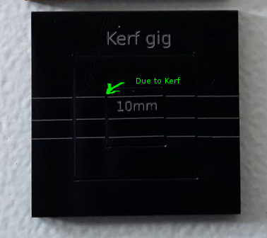
For Finding the Kerf of our machine we have made a kerf gig, which is having a small square of 10mm inner dimension. The Sketch of our gig is showed below, gave some engraving lines for measurement reference
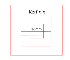
Kerf gig
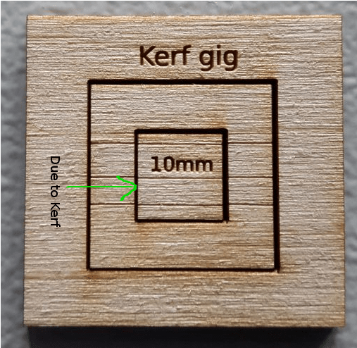
You can see there is a gap in between the cuts, it is due to the kerf of laser. We measured the (i) inner and outer measurements of the gig, (ii) inner and outer rectangle dimensions and taken the average value of the readings, which is the actual kerf value. We got the total kerf as 0.65 this accounts the kerf of two sides of the rectangle. The actual value of the kerf is half of this value. The calculated value of Kerf is 0.65/2= 0.325mm
Calculated value of kerf for craftwood 3mm is 0.325mm
Next we have done the same thing on acrylic sheet of 3mm thickness and repeated the same measurements and calculated the value of kerf. Here we got the total kerf as 0.488mm and the actual Kerf value is half of the total 0.488/2=0.244mm
Calculated value of kerf for Acrylic 3mm is 0.244mm
Accounting Kerf in our designs
We need to account for the kerf within our drawing by adding or subtracting the kerf width from our part dimensions. We have to find out the Kerf for different materials. Once you finalised the kerf, you can use them it into our designs. This is the first thing you have to do before starting the design. In our case for designing in craft wood we have measured the thickness of craft wood is around 3.1mm so while desiging we can give 3.1mm-0.325=2.775 instaed 3.1mm. In the case of Acrylic 3mm it is 3mm - 0.244 = 2.756mm. Sometimes the Kerf may vary with material,foucus of laser etc.
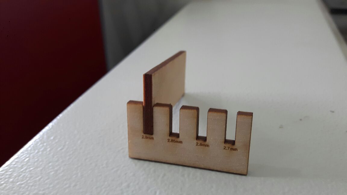
Next we planned and made a gig for proper kerf for pressfit works in craft plywood. So we made a small gig which is having different dimensionla slots starting from 2.9mm for 3.1mm craft wood and found that the 2.9mm (exact slot value with kerf correction) slot is best for the press fit. The frictional force is normal in this case but the others are having very high frictional force. We can check the force manually placing the mating part ,since we don't have any froce measuring equipments in the lab, we have have to do manual judjment.
Power Variation Test
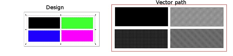
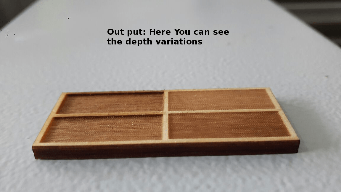
We have also done a power variation test in craft wood. First we made a plate of different colored rectangles for engraving and we have set the power for each different values starting from black color power as 80, power 60 to Blue color, power 40 to Green and power 20 to Violet. The plate is processed and we got different engraving depths in each as expected.
Desigining Part
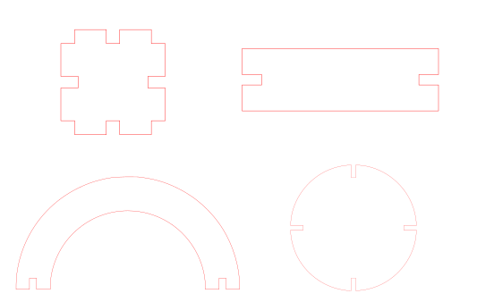
Gone through variuos parametric kits in the fab academy archieves, there are interesting projects in this category. I started design small shapes in antimony so that later it can be connectd and can make different objects. I have identified four basic shapes to design and is showed below.
The parts are basic shapes and given the slots for pressfitting it with the other parts. I will discuss each design in detail below.
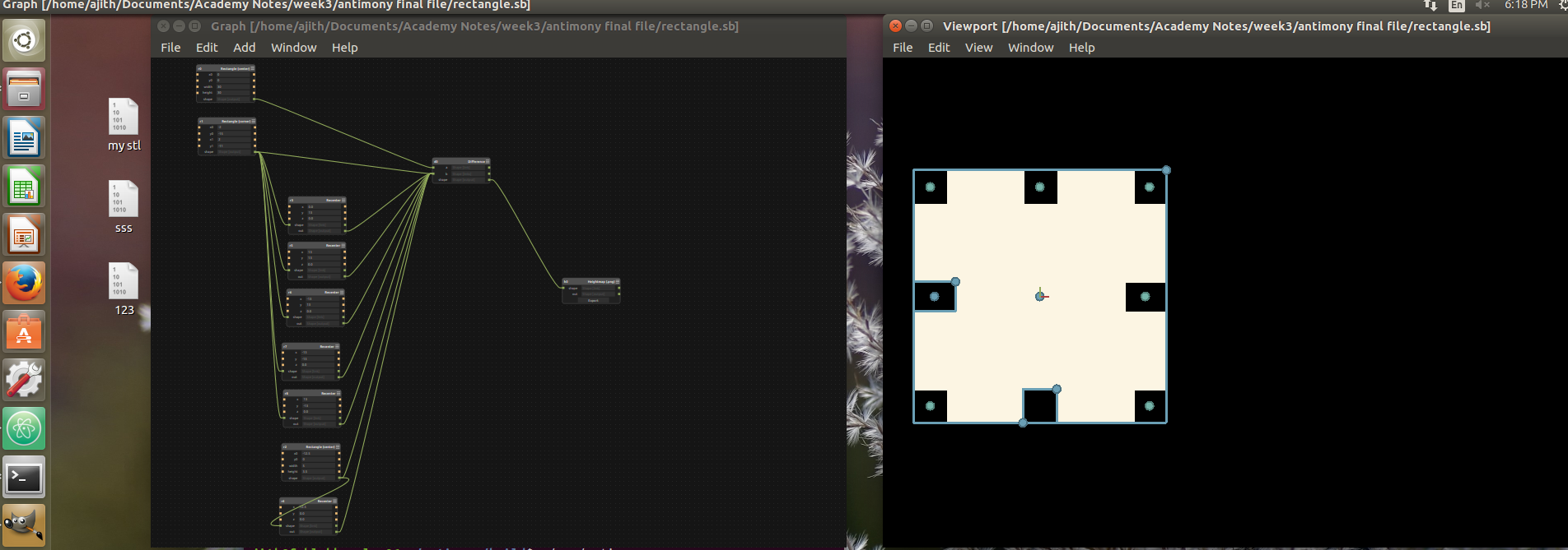
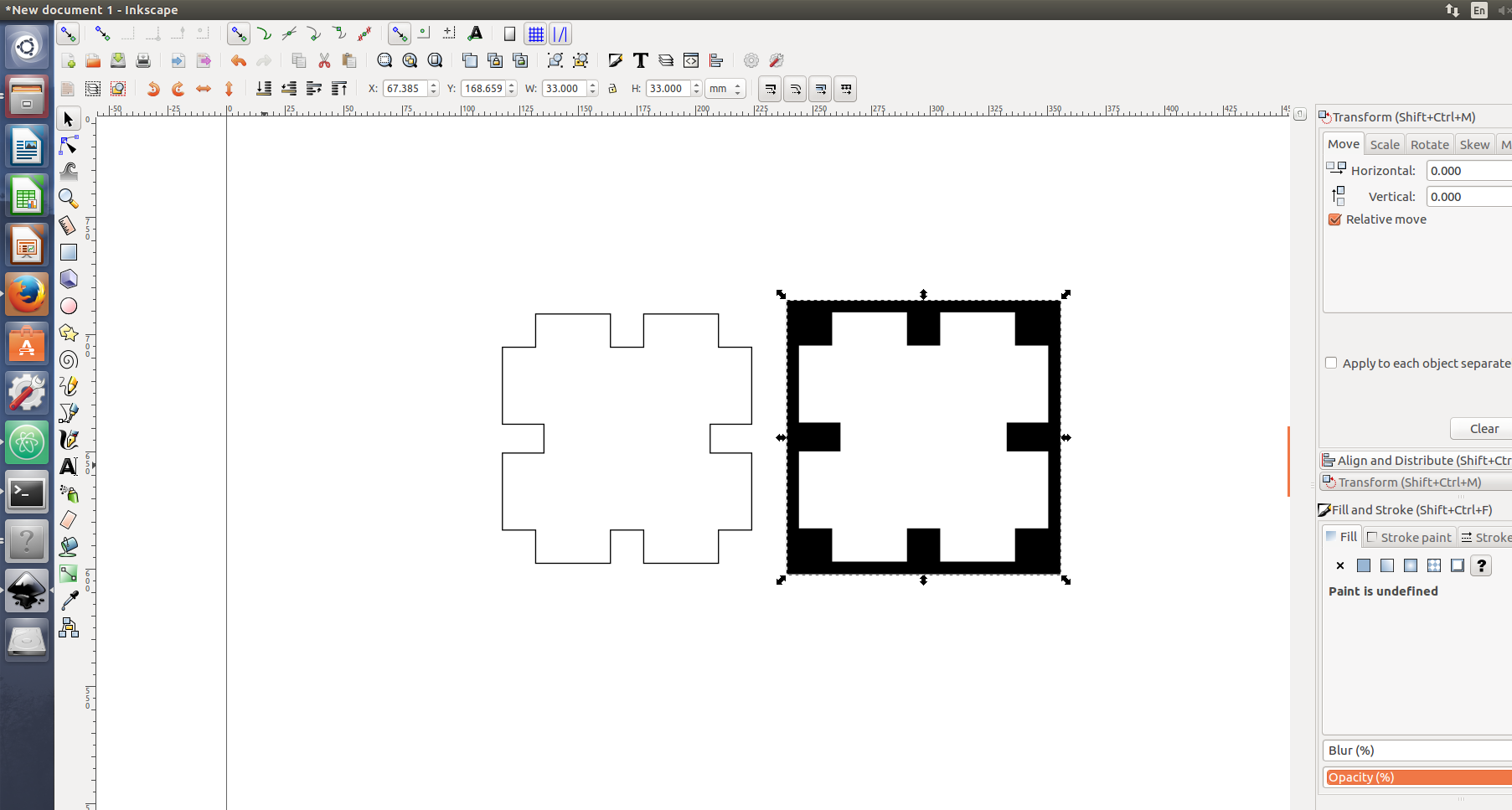
Square part
In the design i had taken a kerf of 0.3mm on both sides and i designed it for carboard sheet. The card board sheet is having 3.8mm thickness so i just given the value of 3.5mm slots for the press fit slots(3.8mm-0.3mm=3.5mm).
Rectangle part
For this part also i have given the same 3.5mm for the slots.
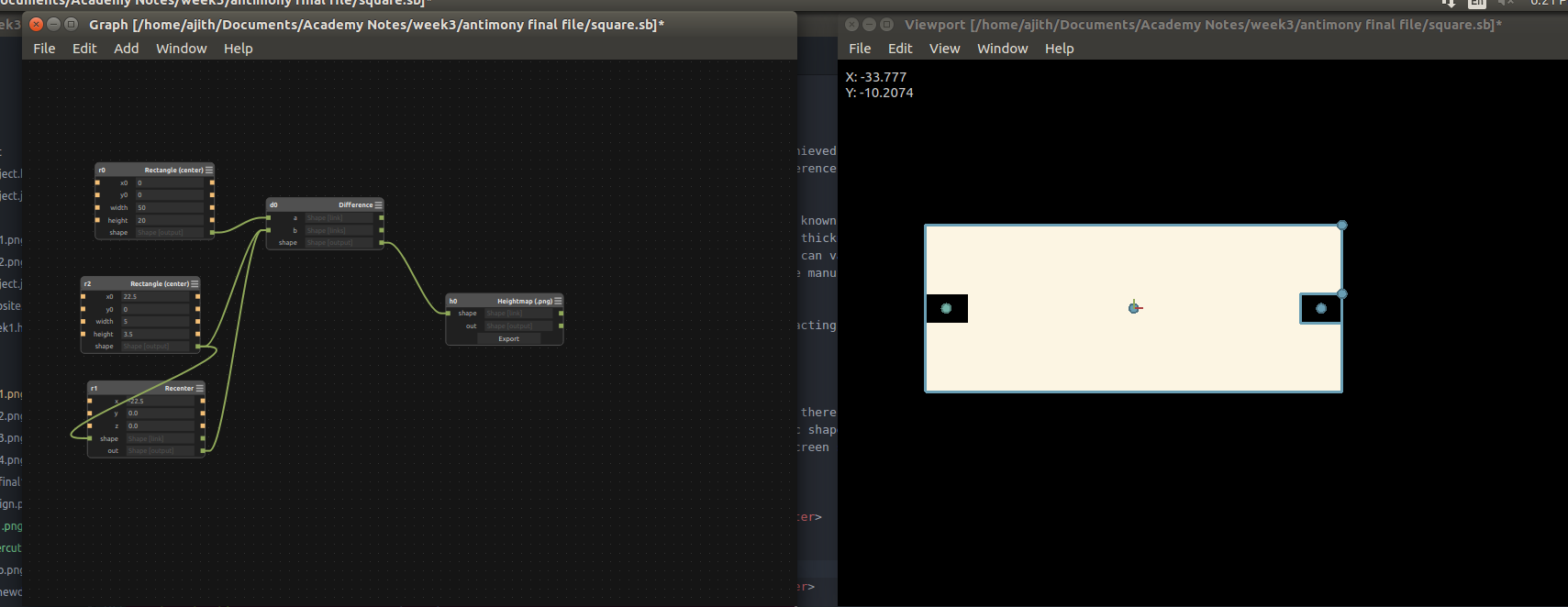
Half circle part
This part was little difficult for me ,Syed helped me to solve the issue so finally i did the design
Circular part
In this circular part i made a simple circle with radius 40mm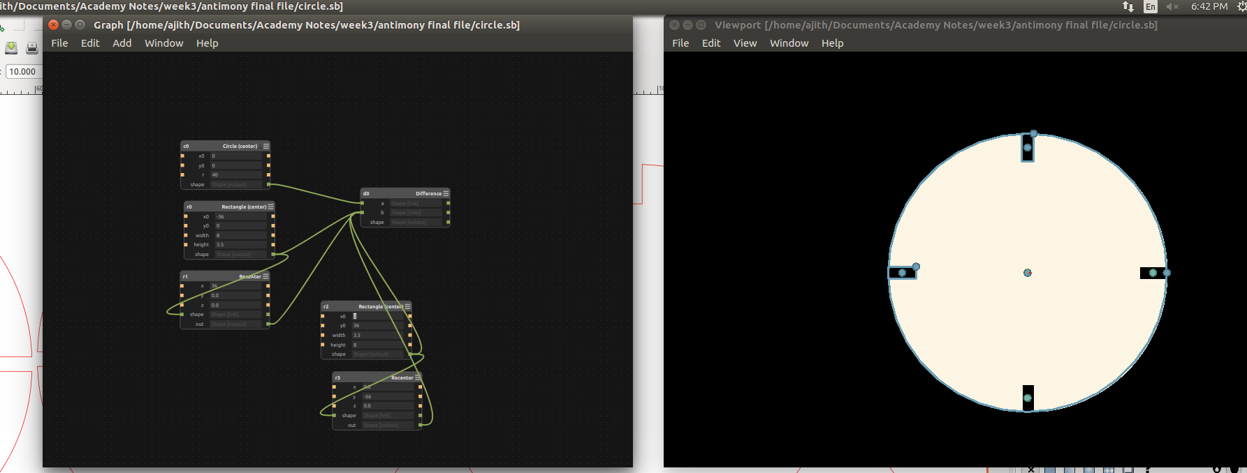
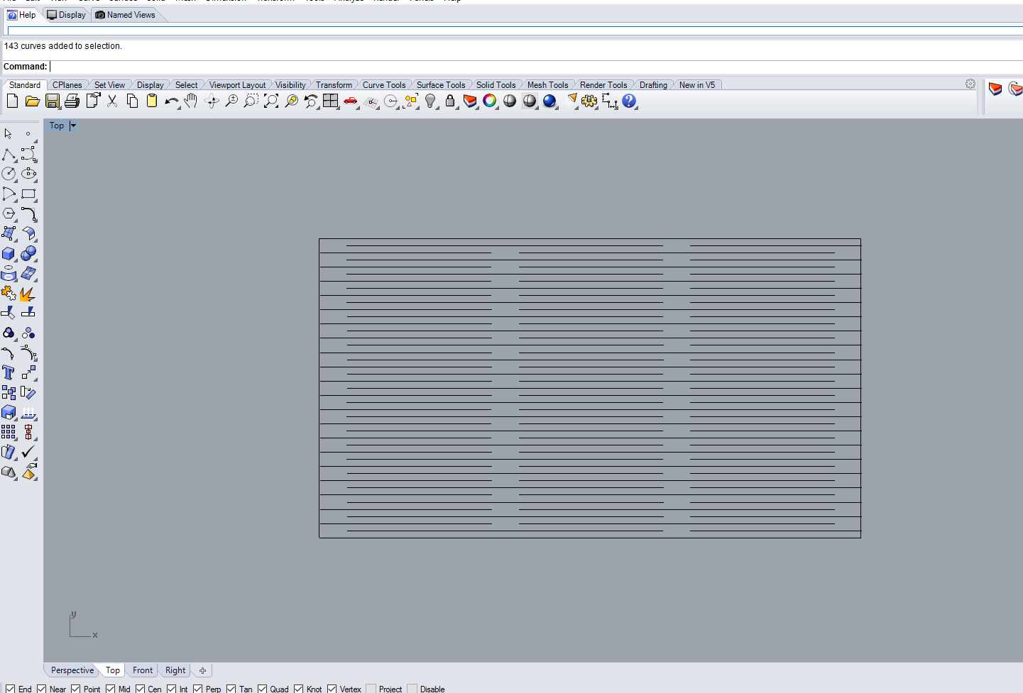
All these are in parametric designs, we can adjust the slot widths and height easily. Finally i exported it from antimony to .png format for the processing it in laser cutter. Laser cutting requires .SVG or .DXF files, but we canconvert our png file using inkscape. In antimony we can't directly export the designs into .dxf or .svg formats.
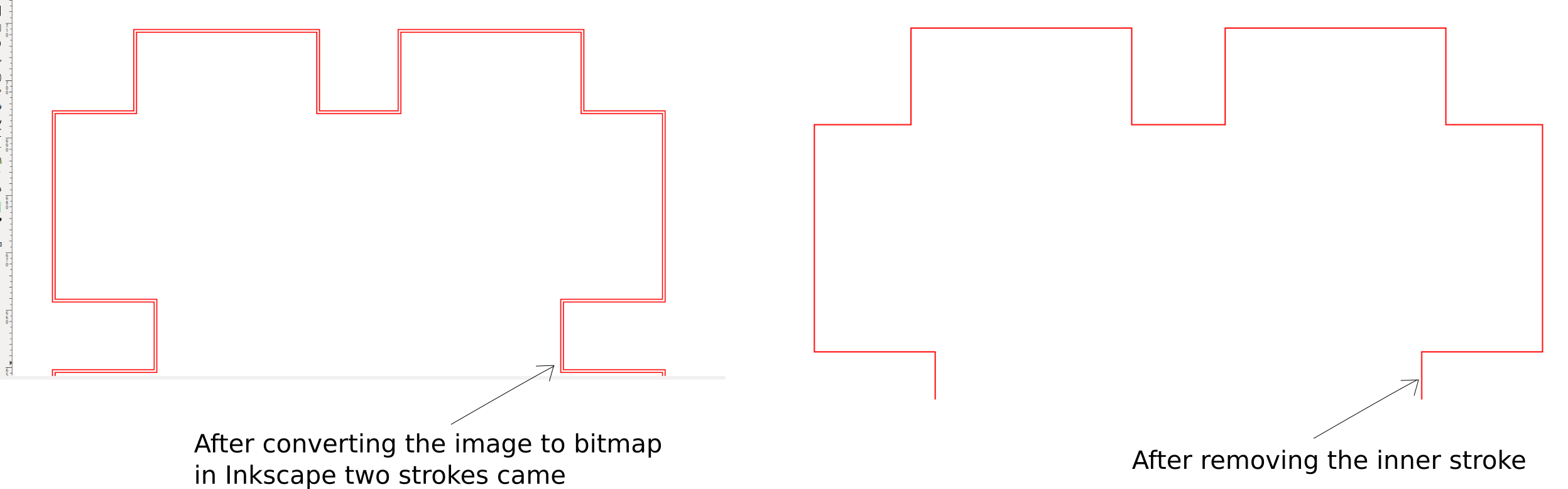
The parts were opened in Inkscape and converted in to bit map , adjusted the threshol level of the bitmap. Here one problem i noticed that while converting it to bit map two strokes are comming instead one. If we leave this as such then the laser will consider this as two different paths and it will cut both and the result will be dimensional deviations. We can simply remove the inner path in Inkscape using break apart option, using that i edited the file and saved it into .dxf format.
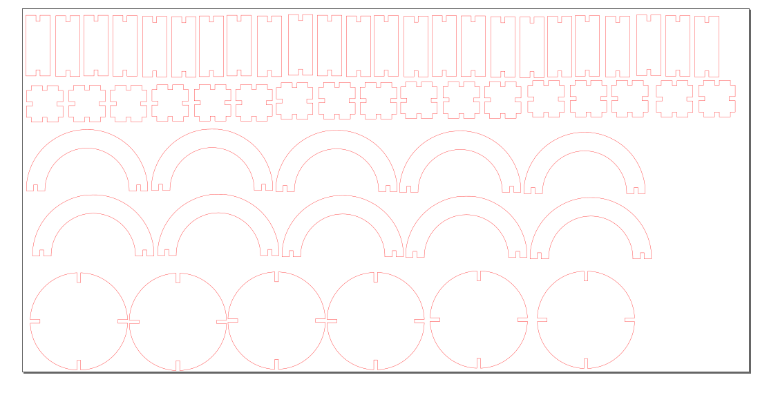
All the parts were edited like this in inkscape and i made a small test cut for each parts in 3ply cardboard sheets. It came correct and finally arranged all my parts in one plate in inkscape i.e the bed size of 600X300mm.
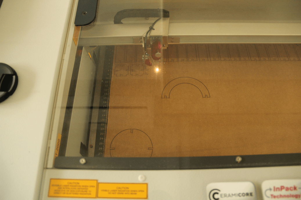
Laser cutting
First we have to turn ON the laser machine. When turning On the macine bed will move downwords ensure every thing is safe and is not showing any errors. After a few seconds the bed
will reach bottom and a beep sound will be heared that is the indication that the machine is ready. Place the material in the bed and raise the bed and tune the focusiing of the laser using
Focussing tool. You can use the X and Y control switches in the control panel mounted on the corner of the laser machine, for moving the Z axis near to X and Y control button there is up and down
arrows that is used as Z axis. Once you have done the tuning, identify the origin to start the cutting that's all. Now we have to go for the software contorls. First we have to open the design ,
In my case i opened it in inkscape my design plate dimension were 600mmX300mm, We can change the document properties and can cut smaller pieces any where in the total available bed area. I selected
the print option and chosen trotech engraver. It will open the trotech speedy100 control panel, In that i have selected material as cardboard and set the powers all the options you can find out by clicking the properties.
Completing this we can send it to laser by pressing the trotec icon from the popup menu. Next Click ready button on the leftside to establish the communication and finding the origin after some time
the panel will show the current position of the laser. On the left side there is job buffer in that we can see our job just double click it and place it in the origin and click ready now the laser will start. Before starting the work remember
to turn On the Filter machine. We have a carbon activated atmos filer system is installed along with laser machine. This will collect all the fumes comming out during cutting and filtered. The process are
shown below.
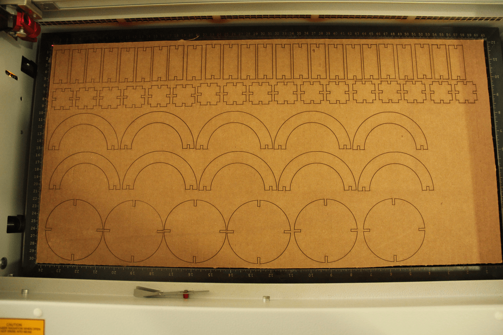
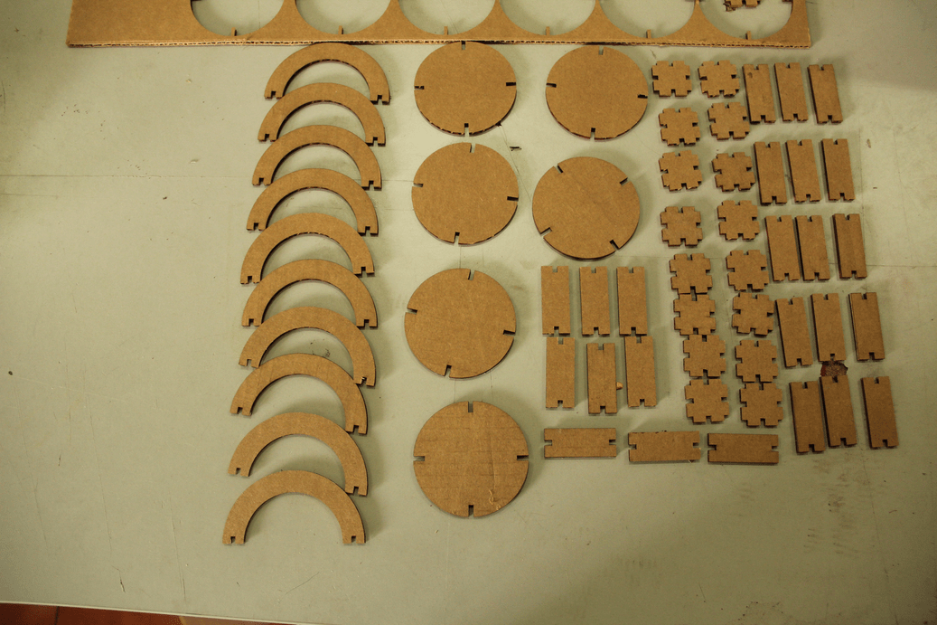
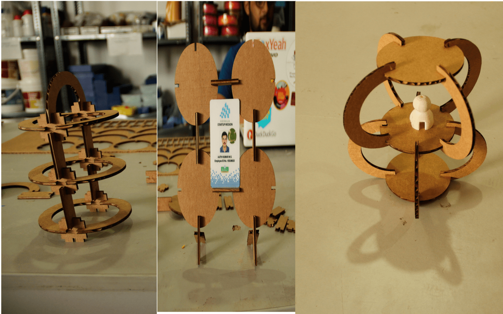
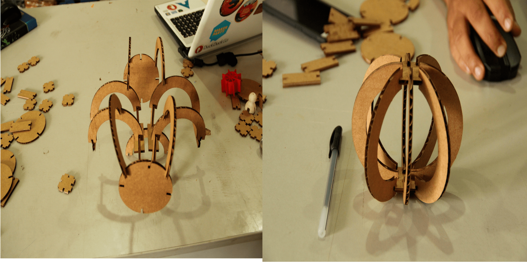
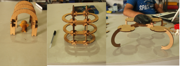
I got all my parts come correctly and next i started to assemble it in different ways and am happy that i created different kits from this. I have created the shapes and made a gif to showcase it.
These are the shapes i made
Download pressfit kit Files(.zip)
Flexture cutting
I have done small testing on laser cutting machine, gone through some of the documentations on designing the laser cutted flexible parts. I am planning to make a carry case for my final project. To test for that i made a small test cut on craftwood in laser. The design was made in rhinocerous and exported to .dxf format and processed like the above in laser cutting machine. The power and velocity settings were there for each material in our lab.
The below showed image is the flexture i made with the laser machine, inorder to check the flexibility normal length of the test piece and the length of the test piece elongation are checked. I think this was a good one that can be usefull for my final project.
Vinyl Cutting
We have Roland GX-24 model vinyl cutting machine in our lab. In this week we have to cut something using vinyl cutter.
Roland Vinyl Machine GX-24
This is basically a XY plotter, having a blade to cut sheets normally we are using it to cut adhessive vinyl sheets, vinyl stencils and flexible printed circuits by using adhessive copper sheets. Using this we can make logos to complex designs. The blades we used is 45 degree blades it is placed in blade holder.The blade extension is to be choosed in such a way that it should be able to cut the top layer alone. The blade extension can be changed using turning the blade extension cap.The blade used and blade holder are showed below.
If you mistakenly increase the blade extension then the blade will pass through the sheet and it may pass through the blade protector.So, We must ensure that the blade extension is correct before doing the cut. The below showed picture i have captured from our vinyl machine using the digital microscope.
Designing Logo
I thought to design and cut a logo for my multimeter , designed the logo in inkscape and saved it to .svg format. Later i had done some more editing to it using Gimp and finally exported to .png format for cutting. Here is my design, I named my project with "SMART MULTIMETER 0.0"

Actually i downloaded .svg logo of fab lab from the internet and made it bitmap in inkscape and added text labels and done design editings. The final editing was done in Gimp and the file is exported as .png file. I planned to make it with different color combinations, So, I selected the green,blue and yellow color Vinyl sheets
Operating on Vinyl CutterInorder to operate the vinyl machine some driver software is required. Fab module is one of the software we are using for this purpose, it is having online version also called "mods". In our lab already fab modules were installed in the pc and i used it. Fab module accepts .png formats and it will convert the .png files to corresponding vector paths and send to the machine.
Steps
cutting steps are explained below:
1. First connect the vinyl cutter with the PC using an USB cable. and Turn ON the machine.
2. Open the terminal from pc and type:
fab # opening fab modules
3.Choose input format and out put process. opened fab module and selected input as .png format and output process as Roland Vinyl cutter(.camm)
and click "make_png_camm" then a new window will open.
4. In the new window
- Load the image
- Resize the image according to your dimensional requirements
- Choose vinyl as material
- Check the pen force
- Make.camm
- Send it to the machine
Machine settings
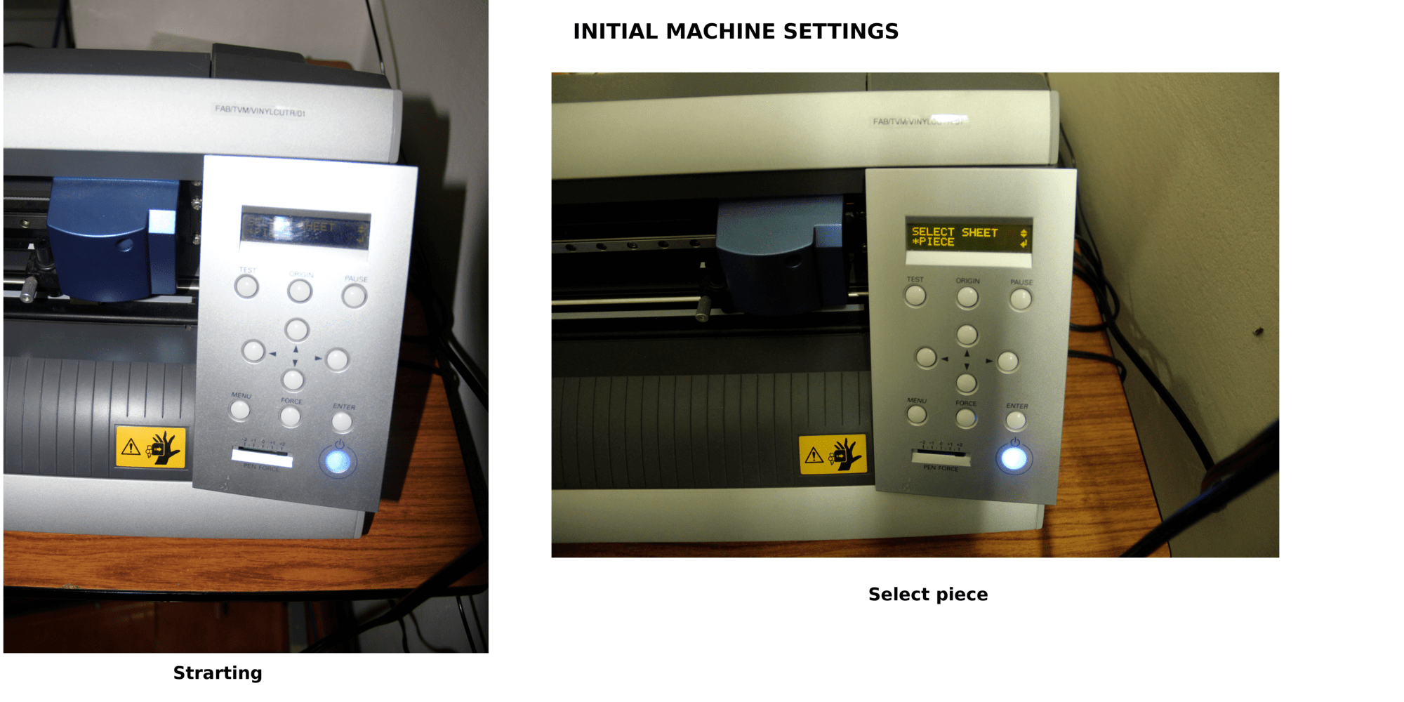
1.Turn ON the machine by pressing the Power button
2.Select the material as piece or roll. Here i used a scrap piece of cinyl sheet so i selected piece option if you are using a roll select "roll".
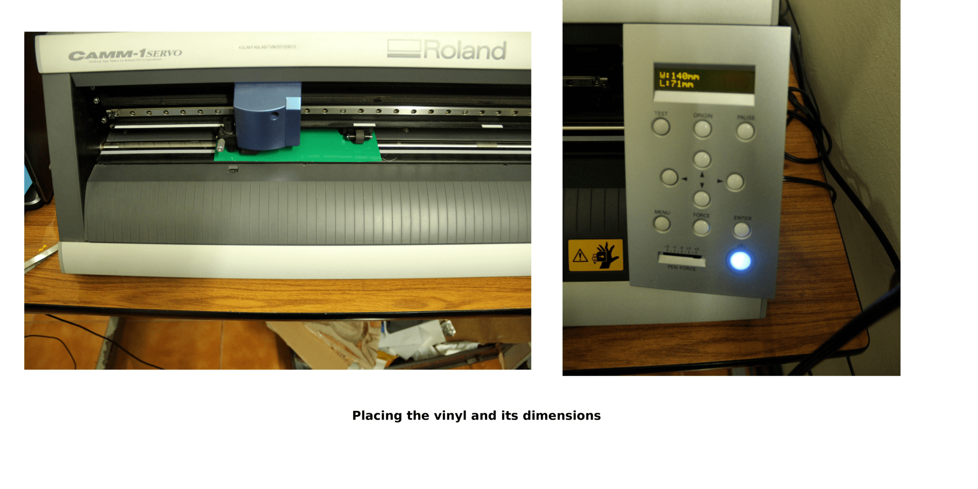
3.Place the Left and right Pincher roller in between the white marks.
4.Check the blade and the blade extension
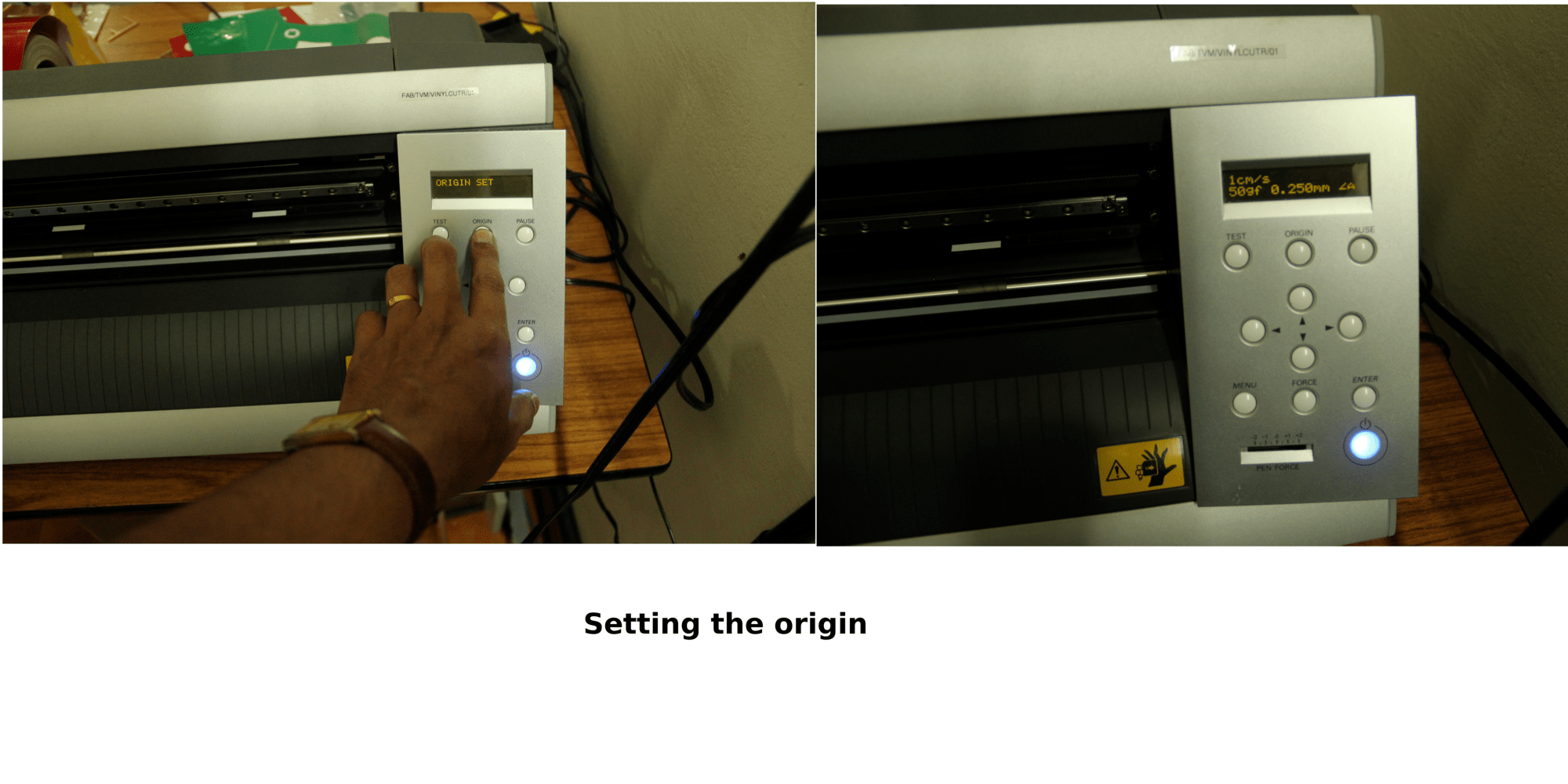
Once if we completed the above we are ready to cut our design. Next step before doing actual cut it is better to do a test cut for that we need to set the origin using the origin button and press the test button in machine. Once its done check the test cut if it is ok then move to next step
5. Select a origin and ensure that our vinyl is having enough space to hold our design, then Press origin button
6. Go to fab modules and ensure other settings espetially the speed settings are same on machine and fab modules. For cutting my logo i used 70gf force but the machine settings were 90gf. I changed it to 70gf on both fab modules and also in the machine.
7. Begin the cutting, here i started with green vinyl sheet
Post processing
After completion of the print i cut the same design in two more colors i.e blue and yellow . Green color is taken as the background, yellow for text and boarder and finally blue color for traces. Transfered all the required colored labels into one vinyl sheet and using the masking tape i transfered it to one of the card holders cap. The multi colored logo for my Project is ready and you can see the images below.
![]()
Deer design
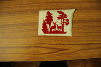
Next I downloaded a design from internet to cut in vinyl cutter. The design is "deers in forest", downloaded it and converted to bitmap using gimp and cutted using vinyl cutter. The design is opened in Roland vinyl cutter (.camm) through fab modules given all the settings .This time given the force as 90gF and started the cutting on Red colored vinyl sheet. Here i will explain the post processing steps with pictures.

Steps
After Cutting in Vinyl machine , My design is transfered to a paper masking tape. This is the first step of the post processing. We have to be extremely carefull in transfering the design to the masking tape. Some times the tape adhesiveness creates issues in that case we can use sompe powders(talcum) or any other methods to reduce the adhessiveness. For this i didn't used any powders.
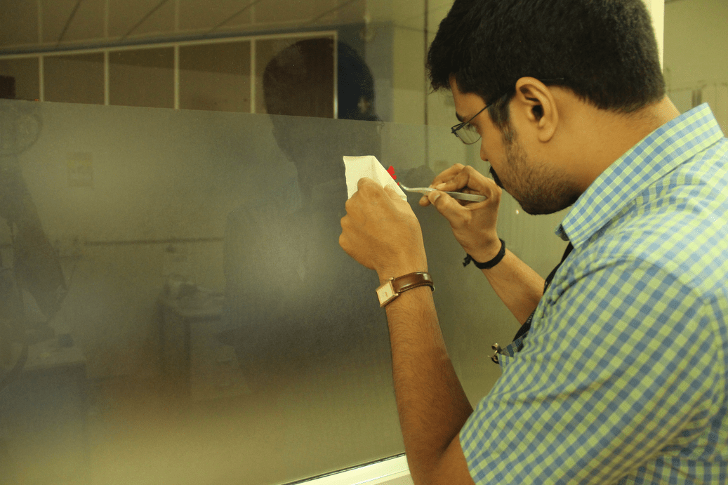
Pasting it on the glass: In this step we have to transfer the design to the destination, Here i selected our electronics lab partition glass for
stickering my design. I pasted it on the glass and applied little force to fix it on the glass. If we apply enough force ,it won't come out during the removal of
masking tape
Removing the mask: Next step is to remove the mask from the glass. Slowly take out the masking tape from one corner
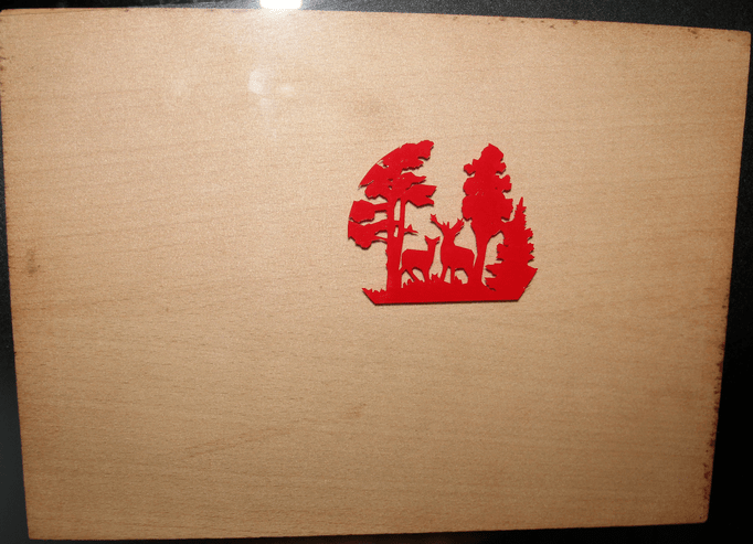
check in between wether our design is not pealing off. My design was perfectly sticked to the glass so the masking tape removal was very easy for me. Final:The final vinyl design was sticked very well in the glass. As it was a glass, i placed a craft plywood in the back side for getting the hero shot of my design. Download vinyl cutting (png) Files(.zip) "Technology is just a tool. In terms of getting the kids working together and motivating them, the teacher is the most important"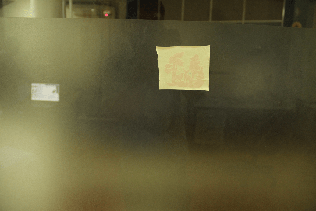
Quote of the Week