WEEK 11
MACHINE DESIGN
ASSIGNMENT
- Automate your machine. Document the group project and your individual contribution.
Preperation
This is the second part of the two week assignment to make a machine as group assignment. We are making a fab version of U arm named "FAB ARM", In mechanical design week we made an initial prtotype of FAB ARM using craft plywood. This week we are palnning to make the final version and automate it using arduino/gestalt node, for that i have gone through ardunio tutorials to control multiple servos and the gestalt node documentation to drive the steppers.
FAB-ARM
FAB-ARM, this is the name we have given to our robotic arm made first in Fab Lab Kerala. It is a miniature 3-axis parallel-mechanism robot arm called U-Arm,
modeled after the ABB PalletPack IRB460 industrial robot arm. The basic design is Arduino-controlled, using 3 servos. Later we have added a linear rail to it additionally, so that it will move through the rails which
add one more degree of freedom also which help us to move objects to do pick and place for some distance. You can go through our group documentation page or my week9: Mechanical design week documentation for further details.
FAB-ARM Group Documentation Week 10:Mechanical Design Documentation
My Tasks
The major task i have done for this week is displayed below.
This week we started with laser cutting the Fab Arm parts in 4mm craft plywood. Actually we made an initial prototype in the previous week and controlled using arduino. The required parts were converted into .dxf for laser cutting and fabricated using our tro tech speedy 100 laser cutting machine in 4mm craft wood. Some dimensional corrections were made by Jim on the base parts in order to accommodate the ball bearing available with us. In the actual design the bearing used are of internal diameter of 35mm and outer dia of 42mm and this was replaced by the ball bearing of 37mm internal dia and 52mm outer dia. The parts were fabricated and assembled successfully. Also Rahul started designing a linear rail for giving the horizontal movement of the entire arm.
I. Electrical configuration
Fab Arm is having 3 servos for basic movements and one stepper mounted to drive the linear rails. After the assembly, 3 servos are mounted on the fab arm and we planned to start testing the servo motors. I worked out an electrical interconnection plan for the project in draw.io and is shown below.
II. Servo programming and calibration
After doing the interconnections myself and renjith tested the servos individually using arduino and identified the electrical limits of the motor, for this we used three 10K resistors and using the potentiometer the angular rotation of the servos are controlled. The potentiometers were connected to the power supply of +5V , Arduino is having 10 bit ADC with the signal range between 0-5V. The mechanical limits of each servo motors will be different and we need to calibrate it before using it. Here is the code we are worked to calibrate the servo motors.
Servo calibration using potentiometers
/add servo library
#include < Servo.h>

//define our servos
Servo servo1;
Servo servo2;
Servo servo3;


int i=100;

//variable to read the values from the analog pin (potentiometers)
int valPot1;
int valPot2;
int valPot3;

char inByte;
int a=5;
void setup()
{ Serial.begin(9600);
  //attaches our servos on pins PWM 9,10,11 to the servos
  servo1.attach(9);
  servo1.write(150);  //define servo1 start position

  servo2.attach(10);
  servo2.write(90); //define servo2 start position

  servo3.attach(11);
  servo3.write(90); //define servo3 start position


}

void loop()
{

  valPot1=100;
  servo1.write(valPot1);
  i=i+a;
  valPot2 =i;
  servo2.write(valPot2);


  valPot3=45;;
  servo3.write(valPot3);
  delay(100);

if(i==145)
a=-5;
if(i==100)
a=5;}
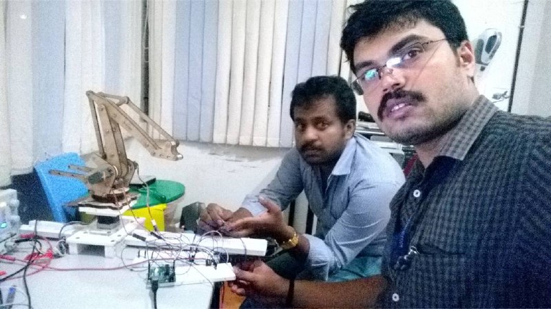
We first understood the code which we got from arduino forums and purchased some potentiometers from the local shop and myself and Renjith did a lot of efforts to make it work. Selfie snap shot of me and renjith during our testing is shown below.
After doing the above calibration we are able to find different points manually and next we planned to change the potentiometers and instead to put the positional values directly to the servo motors in order to move the fab arm in a particular direction. The below showed programm doing the same. The points were given in such a way to move the arm to draw circular shapes.
Servo programm to move fab arm in circular shape

/add servo library
#include < Servo.h>

//define our servos
Servo servo1;
Servo servo2;
Servo servo3;
Servo servo4;


int i=100;

//variable to read the values from the analog pin (potentiometers)
int valPot1[]={100,100,100,100,102,102,102,118,128,138,145,152,152,157,157,157,157,157,157,157};
int valPot2[]={139,137, 113, 88, 71, 71, 71,71, 71, 71, 71, 71,71, 71, 88, 100, 108, 118, 117, 118};
int valPot3[]={45, 45, 45, 45, 45, 86, 76, 76, 76, 76, 76, 76, 76, 76, 76, 76, 76, 56, 48, 45};

char inByte;
int a=1;
void setup()
{ Serial.begin(9600);
  //attaches our servos on pins PWM 3-5-6-9 to the servos
  servo1.attach(9);
  servo1.write(150);  //define servo1 start position

  servo2.attach(10);
  servo2.write(90); //define servo2 start position

  servo3.attach(11);
  servo3.write(90); //define servo3 start position

}

void loop()
{
  for(int i=1;i<=19;i++)
  {
  servo1.write(valPot1[i]); //set the servo position according to the scaled value
  servo2.write(valPot2[i]);
  servo3.write(valPot3[i]);
  delay(500);
  }
  for(int i=19;i>=1;i--)
  {
  servo1.write(valPot1[i]); //set the servo position according to the scaled value
  servo2.write(valPot2[i]);
  servo3.write(valPot3[i]);
  delay(500);
  }

  }
In the above code you can see the default pot values i.e for each potentiometers pot1,pot2 & pot3. After flashing the program the arm started moving in circular movement. But we feel oscillations were there on the arms . We connected a pen to the end effector which i made and it started drawing the circular shapes on the notebook.
III. FABNET Bridge board fabrictaion and Gestalt node Testing
I have gone through the gestalt node documentation from the archives and the documentation by Nadia. Here i will give a breif introduction about what is a gestaltnode?
Gestalt Node
Gestalt node is a small electronic control board that can be easily networked and connects via Fabnet USB to your computer and to the steppers. It looks like it is not yet commercially available but you could make it yourself if you are experienced with electronics (Gestalt Node GitHub). To know more click the link. The programming interface of gestalt node is shown in the figure.
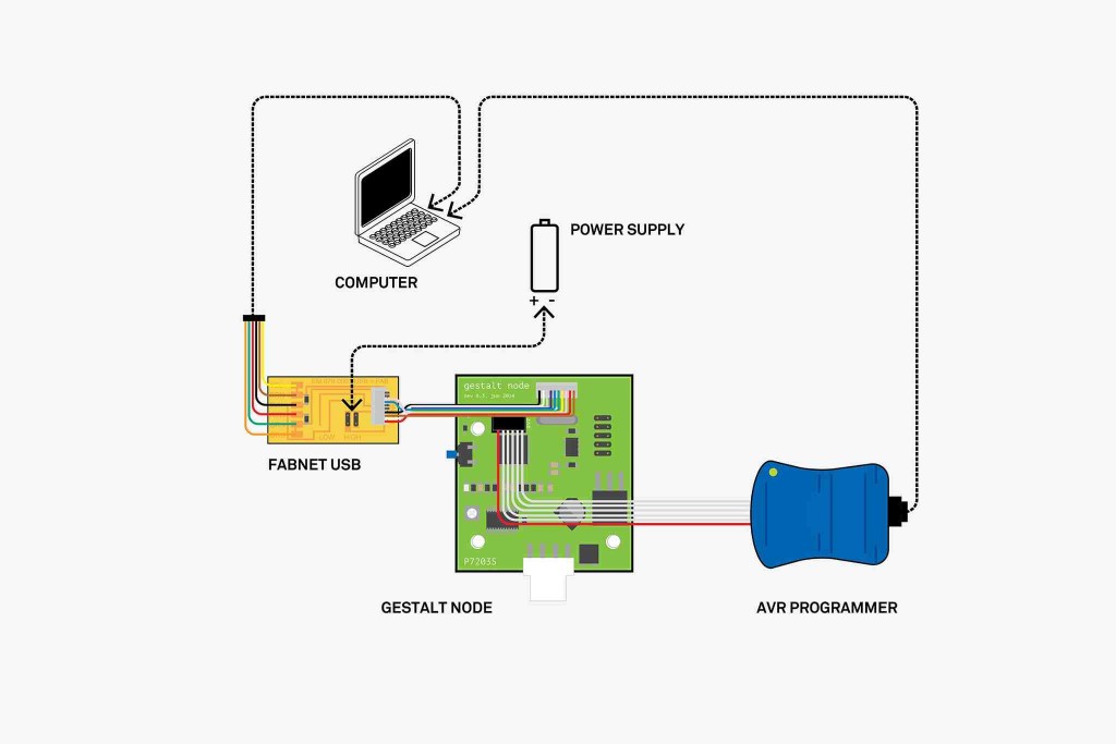
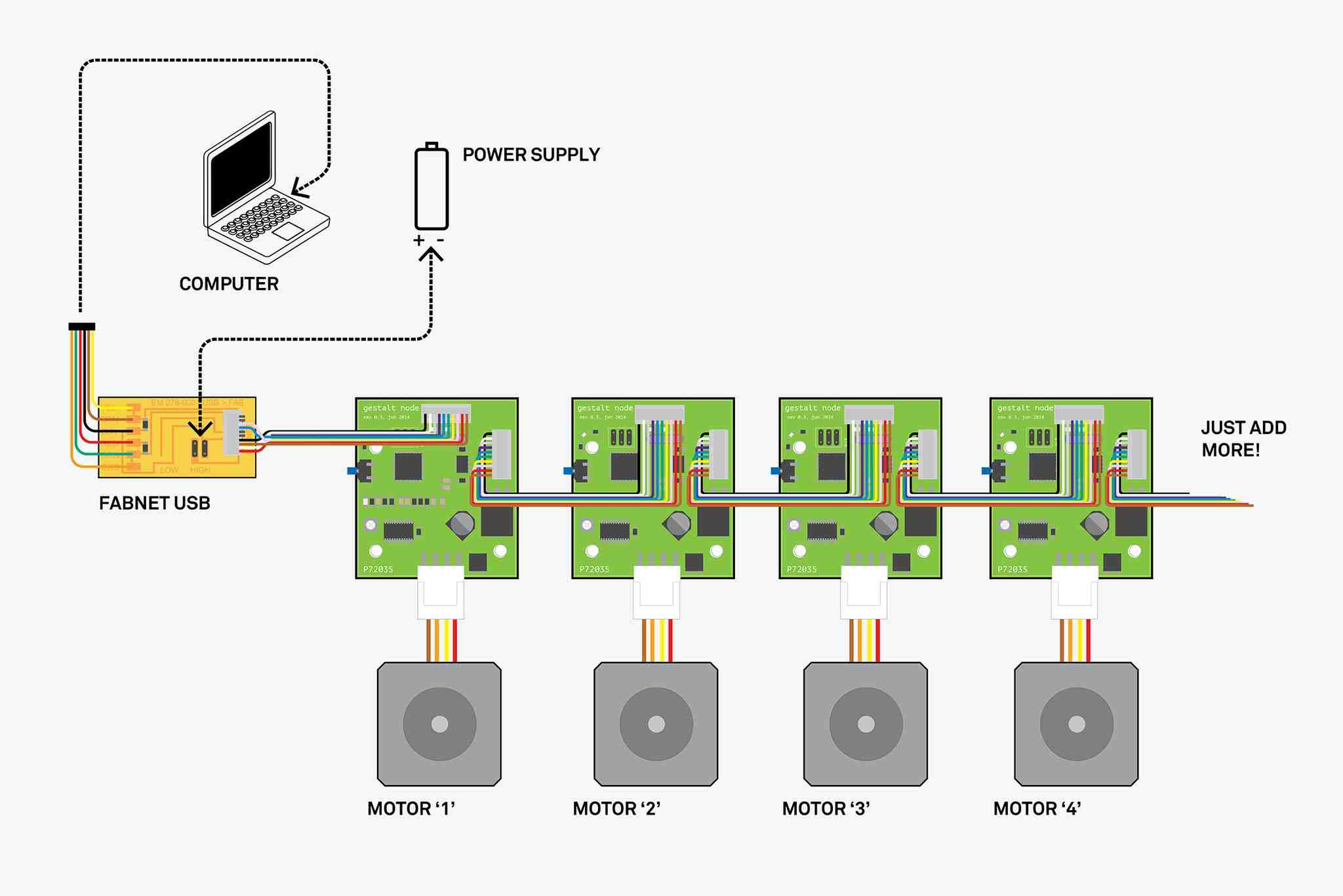
The configuration of gestalt with stepper motors is shown in the below figure , all these are the images i got from the above link and here i am copying it for the reference.
Gestalt framework is a high level Python code that powers it all, you can see it on Gestalt GitHub. As I went through the complex description I could only understand that the user will use it via “Python interface consisting of function calls to procedures and a remote interface to make procedure calls through http requests”. So you will need to know Python programming and the Gestalt will move your machine by using the Gestalt nodes without g-code.
To know about the whole about MTM you can refer the documentation link
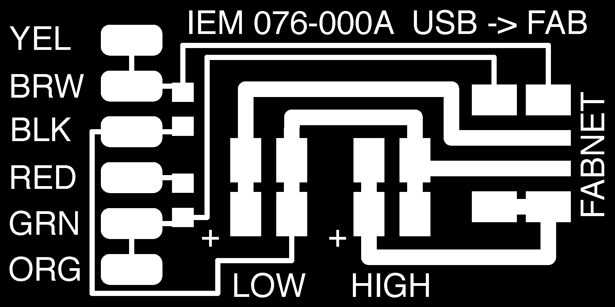
FABNET Bridge Board
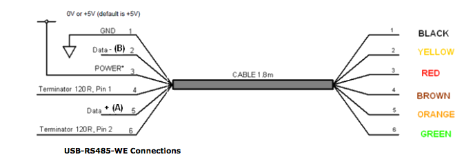
FFabnet Bridge board is the interface board between the PC and individual gestalt nodes called fab nets. Individual Fabnet contains an RS-485 bus with a few additional signals. FTDI cable is used for communicating with the fab nets using fabnet bridge board. The FTDI cable provided is a little different than the other FTDI cables we've been using; it is an RS-485 version. Here's its pinout for reference:
We need to create a bridge board, the files are already available from the link. The design files were opened in eagle software and exported it to png files and processed using modela CNC. The steps i followed are the same in my electronic production weeks. The Pcb is simple one to split the FTDI lines to gestalt node. It is having two 604 ohm resistors which is not in the inventory part and we got it as the part of gestalt node.The pcb milling and cutout files are given below.
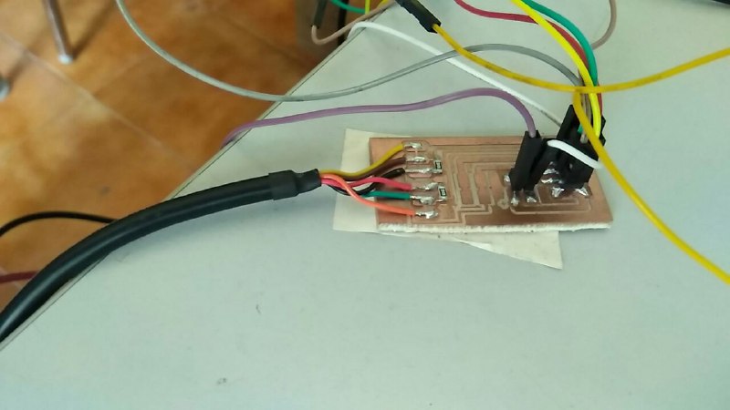
The pcb is milled and soldered two resistors and the FTDI cable as per the layout diagram and final board is shown below.
After making this we started programming the gestalt node and it was showing some errors, as i am not aware of python program ganadev and sreejith did the rest of the testing and finally it worked. You can see the below video it is working as cleaning work with a stepper linear guide rails made by rahul and sreejith has made the end effector.