WEEK 16
INTERFACE AND APPLICATION PROGRAMMING
ASSIGNMENT
- Write an application that interfaces with an input and/or output device that you made, comparing as many tool options as possible.
Preperation
My plan for this week is to make a ultrasonic sensor based distance detection system for my bike. I am planning to use the Attiny44 breakout board, which i used for input devices week. I have gone through the MIT app inventor software tutorials for developing the android app to interface the board.
UDDSB
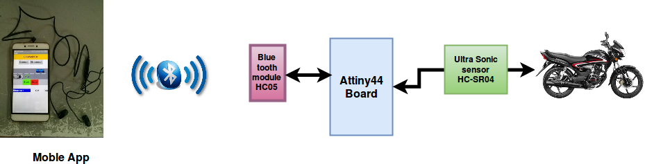
The name i have identified for my system is UDDSB- Ultrasonic Distance Detection System for Bike. I have a bike and i love riding bike why because i can go where ever i want to go at any time. At the same time I see the risk of riding it in the middle of traffic, where i need to check all sides for the clearence. So while thinking what to do on this week , suddenly this idea came ito my mind. My plan is to make an android app to interface ultrasonic sensor through Attiny44 based breakout board and Bluetooth module HC05 using MIT's app inventor. The output of the system will be distance in centimeters in the form of audio, So while riding the bike you just need to wear a headset so that you will get the exact clearance information or we can fit a display in the front panel. The Block schematic of UDDSB is shown below.
App inventor
App inventor is a cloud based software provided by Google and maintained by MIT to create applications for Android systems. First i have gone throuh the documentations and tutorials on how to make the app in appinventor.There is a colection of tutorials are available in mitappsinventorblog. You can follow this documentation on how to start designing apps using app inventor.
First i registered in the app inventor site app inventor. Start a New project ,then you will be directed to the designer window from here we can add the user interfaces like buttons, labels, textboxes, text to speetch etc. Next is the Blocks section after adding the user interfaces into the designer part we can move to blocks section. In the blocks editor the user interfaces we added from designer section can be connected to perform the tasks, for each user interfaces number of palettes will be available. The palettes can be picked and placed in the block design area and connected with other palettes.
Bike sensor app design
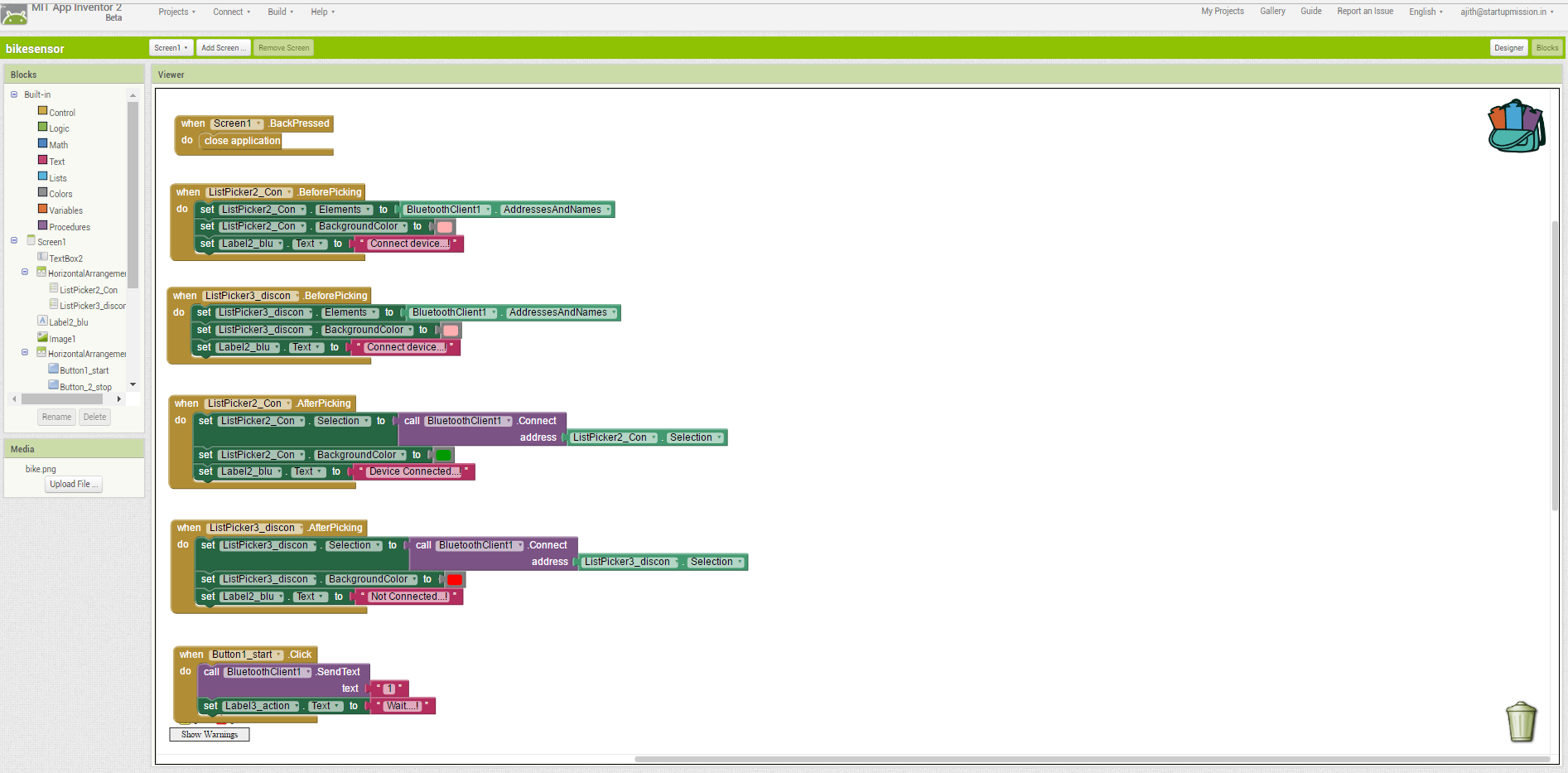
After learning from the video tutorials, i started designing my app. Added buttons,text boxes,labels, bluetooth client and text to speech to the designer area. Then customised those buttons as per my requirements. The core image i downloaded from internet and cropped and imported the .jpg image to the design area. My initial design screen shots are shown below.
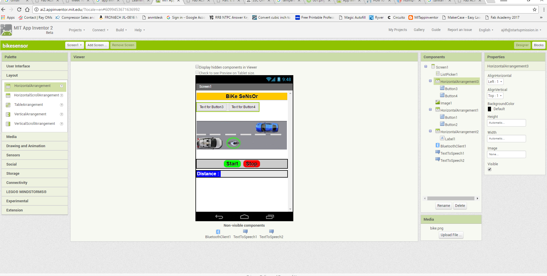
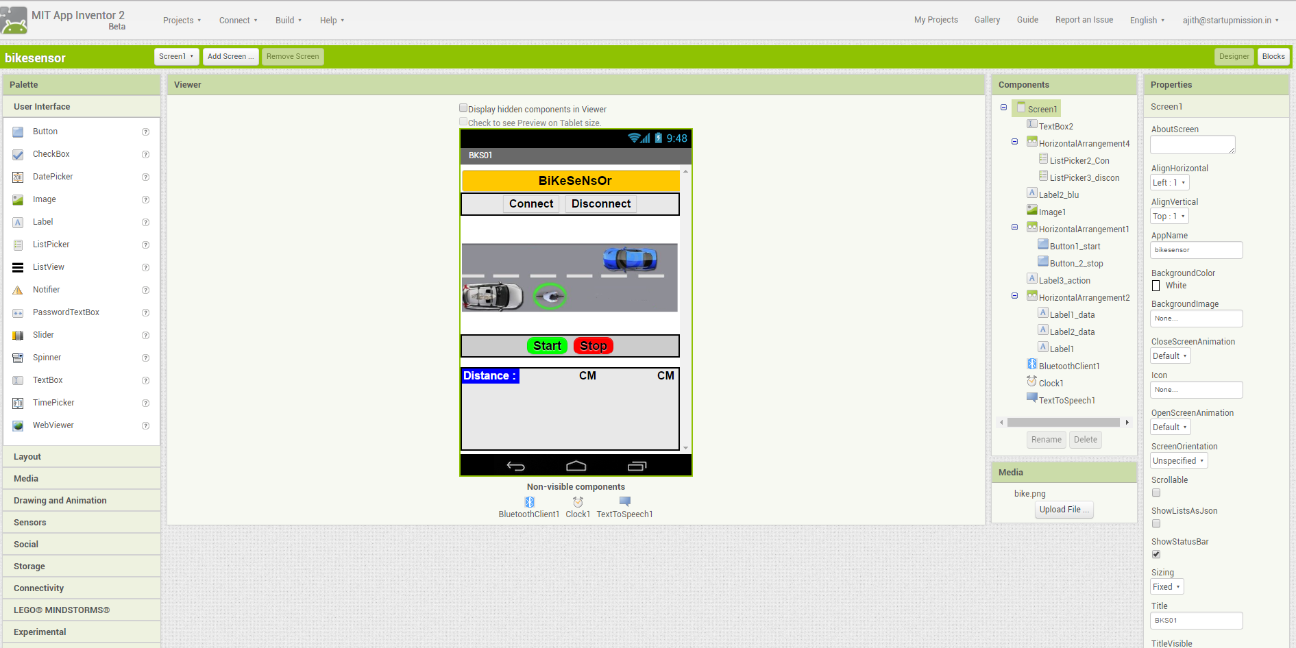
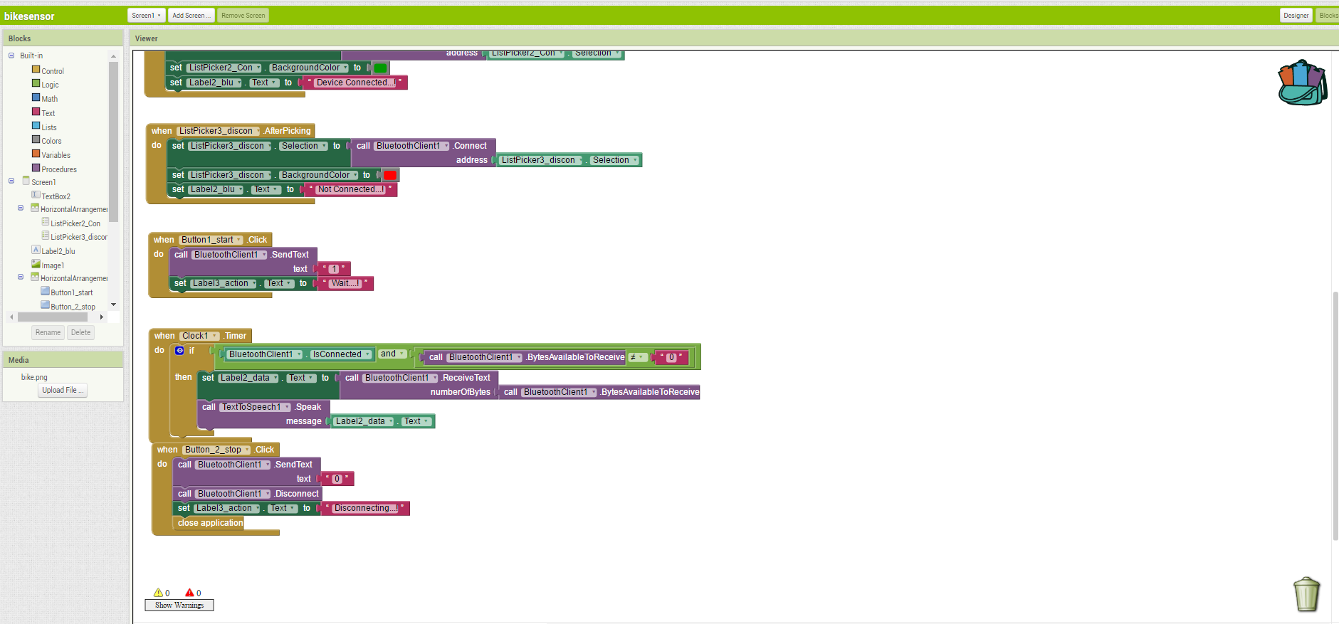
After completing the design satge i moved to the block stage where edited the individual designed blocks according to my requirement. One of the important thing to be taken care is while dealing with bluetooth the palettes need to be placed correctly otherwise it won't work. After a few hours work i completed the app design which is shown below. The data received from the ultrasonic sensor is displayed on the distance measurement area on the app and it will be on Centimeters.
Next stage is moving to blocks plate, there i arranged the different palletes for the userinterface and completed the app. You can add extra settings under each section.
Once we made the app , to test the app live using AI Companion option. What we need is to download and install MIT AI2 Companion app from the google play store
to mobile and install it. Open the app and from the app centre choose "AI companion" it will show a QR code for aour app scan the QR code using the MI2 AI companion app from mobile and connect
to the app. While designing itself we can connect and test our app, I made several mistakes in between and i corrected all those errors. finally my app is ready.
Note: The computer used for designing the app and the mobile needs to be in same network otherwise it won't connect to our app.
UDDSB board
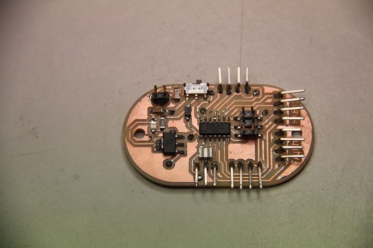
Once the app is ready , Next is to make the boards and sensors be ready for testing. Here am planning to use the pcb board called FTH display board , i made in week 13. It is a Attiny44 based break out board where we can connect multiple inputs or outputs. The details of the pcb is well described in week13 assignment. However, i will share my schematic and board here.
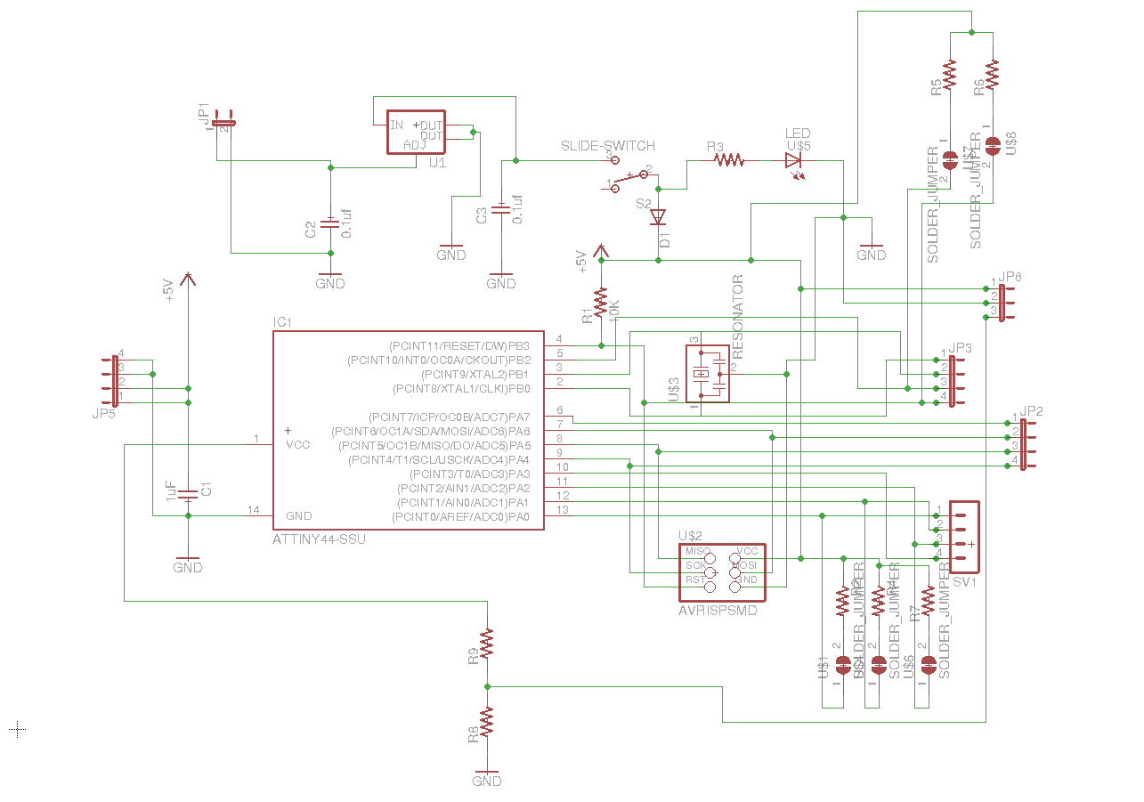
The board am using here is shown below it is a double side pcb.
HC05 Bluetooth module
Bluetooths a wireless technology standard for exchanging data over short distances (using short-wavelength UHF radio waves in the ISM band from 2.4 to 2.485 GHz) from fixed and mobile devices, and building personal area networks (PANs). Range is approximately 10 Meters (30 feet).
Hardware Features
- Typical -80dBm sensitivity
- Up to +4dBm RF transmit power
- Low Power 1.8V Operation ,1.8 to 3.6V I/O
- PIO control
- UART interface with programmable baud rate
- With integrated antenna
- With edge connector
The HC05 module is shown below, the pinout details is given just below that.
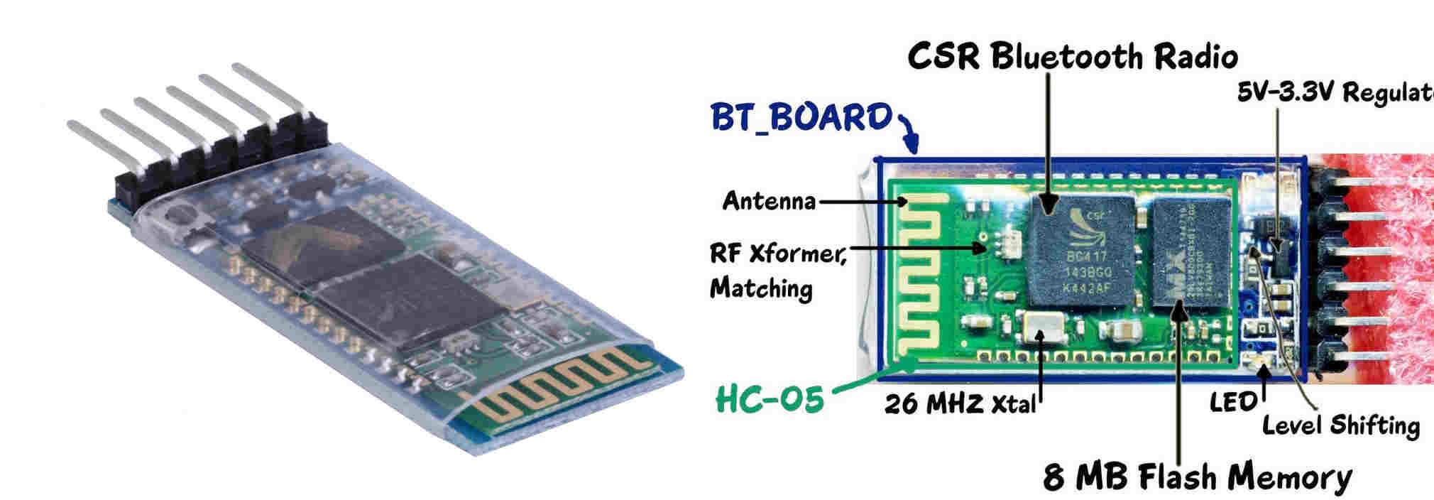
HC-05 PinOut :
- KEY: If brought HIGH before power is applied, forces AT Command Setup Mode. LED blinks slowly (2 seconds)
- VCC: +5 Power
- GND: System Ground
- TXD: Transmit Serial Data from HC-05 to Serial Receive
- RXD: Receive Serial Data from the board Serial Transmit
- STATE: Tells if connected or not
HC-SR04 Ultrasonic sensor module
The HC-SR04 ultrasonic sensor uses sonar to determine distance. It offers excellent non-contact range detection with high accuracy and stable readings in an easy-to-use package. From 2cm to 400 cm or 1” to 13 feet. It operation is not affected by sunlight or black material like Sharp rangefinders are (although acoustically soft materials like cloth can be difficult to detect). It comes complete with ultrasonic transmitter and receiver module.
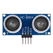
Features:
- Power Supply :+5V DC
- Quiescent Current : <2mA
- Working Currnt: 15mA
- Effectual Angle: <15°
- Ranging Distance : 2cm – 400 cm/1" - 13ft
- Resolution : 0.3 cm
- Measuring Angle: 30 degree
- Trigger Input Pulse width: 10uS
- Dimension: 45mm x 20mm x 15mm
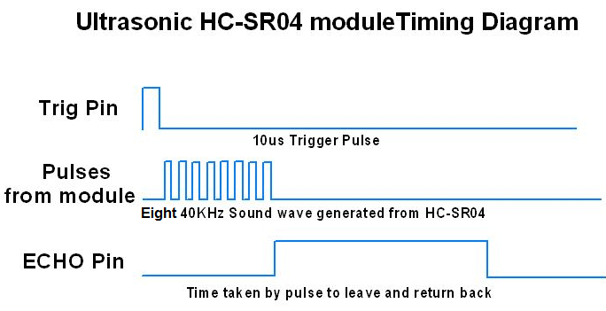
The timing diagram of HC-SR04 is shown. To start measurement, Trig of SR04 must receive a pulse of high (5V) for at least 10us, this will initiate the sensor will transmit out 8 cycle of ultrasonic burst at 40kHz and wait for the reflected ultrasonic burst. When the sensor detected ultrasonic from receiver, it will set the Echo pin to high (5V) and delay for a period (width) which proportion to distance. To obtain the distance, measure the width (Ton) of Echo pin.
Integration
After studying the working and pinout of the modules, Next is to integration and testing of the app. The Ultrasonic sensor module and the bluetooth module were placed in a bread board and the connections were takenout and connected to the attiny44 breakout board. First i thought to implement it using Arduino uno, accordingly connections were made.
Bike sensor app testing
Arduino uno and other sensor modules were interconnected, next i started the programming. Here i used arduino as the programming language, refered some programs from the documentations on ultrasonic interfacing and bluetooth interfacings and edited the code.
/*
* Ultrasonic Sensor HC-SR04 and Arduino Tutorial
*
* Crated by Dejan Nedelkovski,
* www.HowToMechatronics.com
*
* Edited by Ajith kumar in Fab Academy 2017
*
*/
#include < Ultrasonic.h>
#include < SoftwareSerial.h>
#define RxD 0
#define TxD 1
// defines pins numbers
const int trigPin = 3;
const int echoPin = 4;
// defines variables
long duration;
int distance;
//char dist;
Ultrasonic ultrasonic(3,4);
SoftwareSerial blueToothSerial(RxD,TxD);
void setup() {
pinMode(trigPin, OUTPUT); // Sets the trigPin as an Output
pinMode(echoPin, INPUT); // Sets the echoPin as an Input
Serial.begin(9600); // Starts the serial communication
blueToothSerial.begin(9600);
}
void loop() {
// Clears the trigPin
digitalWrite(trigPin, LOW);
delayMicroseconds(2);
// Sets the trigPin on HIGH state for 10 micro seconds
digitalWrite(trigPin, HIGH);
delayMicroseconds(10);
digitalWrite(trigPin, LOW);
// Reads the echoPin, returns the sound wave travel time in microseconds
duration = pulseIn(echoPin, HIGH);
// Calculating the distance
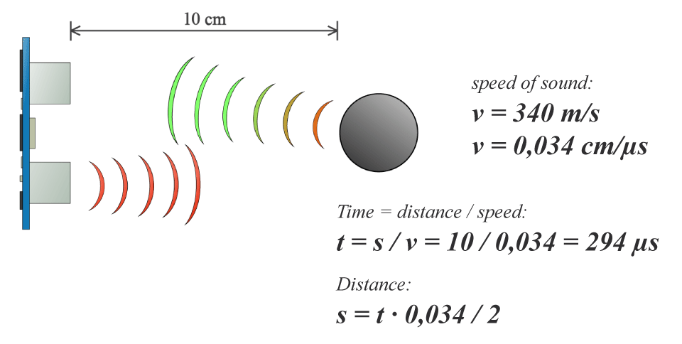
distance= duration*0.034/2;
// Prints the distance on the Serial Monitor
//Serial.print("Distance: ");
Serial.println(distance);
//dist = char(distance);
//Range = ultrasonic.Ranging(CM)
blueToothSerial.write(distance);
delay(1000);
}
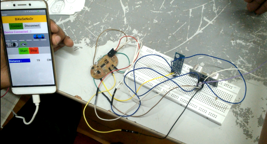
In the above program the arduino pin nos 0 and 1 given for communicating between blutooth module and arduino. Digital pin 3 is identified for ultrasonic sensor triger pin and pin no 4 to echo pin. Then the communication is beeing started and the distance calculation is performed, finally it is send to the app through the bluetooth module. The output of the above program with my app is shown below.
Bikesensor using Attiny44 breakout board
Issues Faced
Next i changed the program to work with my attiny44 breakout board, for this i first selected PA1 and PA2 pin as Rx and Tx for the communication and PB2 as trigger and PA7 as echo pin for the ultrasonic sensor. Conections to the board were made as per the program. PA1 and PA2 to the bluetooth module , PB2 and PA7 to ultrasonic sensor, VCC and GND points were connected. The power to the whole system were taken from Arduino. i.e 5V and GND points were connected from Arduino. Programmed the board using arduino IDE using Fab ISp by selecting the programming board as usbtiny and board as attiny44, clock frequency as 20MHz and tested with the program and it didn't work the code and the output is shown below. You can see the board is receiving the data but instead displaying distance in numeric it is showing characters as the output.
	/*
* Bike sensor App
*
*Ultrasonic Sensor HC-SR04 and Arduino Tutorial
* Crated by Dejan Nedelkovski,
* www.HowToMechatronics.com
* Edited by Ajith Kumar M G in fab Acdaemy2017
*
*/
#include < avr/io.h>
#include < Ultrasonic.h>
#include < SoftwareSerial.h>

#include < util/delay.h>

#define RxD PA1  Pin PA1 assigned as Receiver
#define TxD PA2  Pin PA2 assigned as transmitter
// defines pins numbers
#define trigPin PB2 Pin PB2 assigned as trigger
#define echoPin PA7 Pin PB2 assigned as echo
// defines variables
long duration;
int distance;
//char dist;
Ultrasonic ultrasonic(trigPin,echoPin);
SoftwareSerial blueToothSerial(RxD,TxD);
void setup() {
pinMode(trigPin, OUTPUT); // Sets the trigPin as an Output
pinMode(echoPin, INPUT); // Sets the echoPin as an Input

blueToothSerial.begin(9600);
}
void loop() {
// Clears the trigPin
digitalWrite(trigPin, LOW);
delayMicroseconds(2);
// Sets the trigPin on HIGH state for 10 micro seconds
digitalWrite(trigPin, HIGH);
delayMicroseconds(10);
digitalWrite(trigPin, LOW);
// Reads the echoPin, returns the sound wave travel time in microseconds
duration = pulseIn(echoPin, HIGH);
// Calculating the distance
distance= duration*0.034/2;
// Prints the distance on the Serial Monitor
//Serial.print("Distance: ");
blueToothSerial.println(distance);
//Serial.println(distance);

//Range =  ultrasonic.Ranging(CM)
blueToothSerial.write(distance);
delay(1000);
}
I got confused how to solve this issue, while reading some documentations they mensioned it is due to the comminication baud rate problem. Actually arduino is working on 16MHz external clock and my Attiny44 biard is working on 20MHz external clock. I thought this may be the issue,and i tried changing the baud rate of serial communication, but it didn't worked.
Final Program
I thought to prescale the clock inorder to sychronise the baud rate, as a try i changed all the pinouts to the bluetooth and ultrasonic sensor and finalised the baud rate as 9600. The complete program is shown below.
	/*
* Bike sensor App
*
*Ultrasonic Sensor HC-SR04 and Arduino Tutorial
* Crated by Dejan Nedelkovski,
* www.HowToMechatronics.com
* Edited by Ajith Kumar M G in fab Acdaemy2017
*
*/
#include < avr/io.h>
#include < Ultrasonic.h>
#include < SoftwareSerial.h>

#include < util/delay.h>

#define RxD PA7   Pin PA7 assigned as Receiver
#define TxD PA6	  Pin PA6 assigned as transmitter
// defines pins numbers
#define trigPin PA5   Pin PA5 assigned as trigger
#define echoPin PA4   Pin PA4 assigned as echo
// defines variables
long duration;
int distance;
//char dist;
Ultrasonic ultrasonic(trigPin,echoPin);
SoftwareSerial blueToothSerial(RxD,TxD);
void setup() {
pinMode(trigPin, OUTPUT); // Sets the trigPin as an Output
pinMode(echoPin, INPUT); // Sets the echoPin as an Input

blueToothSerial.begin(9600);
}
void loop() {
// Clears the trigPin
digitalWrite(trigPin, LOW);
delayMicroseconds(2);
// Sets the trigPin on HIGH state for 10 micro seconds
digitalWrite(trigPin, HIGH);
delayMicroseconds(10);
digitalWrite(trigPin, LOW);
// Reads the echoPin, returns the sound wave travel time in microseconds
duration = pulseIn(echoPin, HIGH);
// Calculating the distance
distance= duration*0.034/2;
// Prints the distance on the Serial Monitor
//Serial.print("Distance: ");
blueToothSerial.println(distance);
//Serial.println(distance);

//Range =  ultrasonic.Ranging(CM)
blueToothSerial.write(distance);
delay(1000);
}
Programmed the board using fab isp and connected the board using the app and it start worked correctly. I don't know what exactly happened may be due to some loose contact issues. After that i downloaded the .apk file of my app into smartphone and installed the app and connected the bluetooth device and worked correctly. Sometimes it was showing error readings, i have to look further to reduce those errors. The hero shot of my test setup and working video of my bikesensor is shown below.