
Mechanical Design
Assignment:
- Design a machine (mechanism+automation), including the end effector
- Build the passive parts and operate it manually
- Document the group project and your individual contribution
For this week's group assignment, we agreed to make a CNC plotter. I was allocated design and fabrication of the stand. The design was based on the shopbot stand.
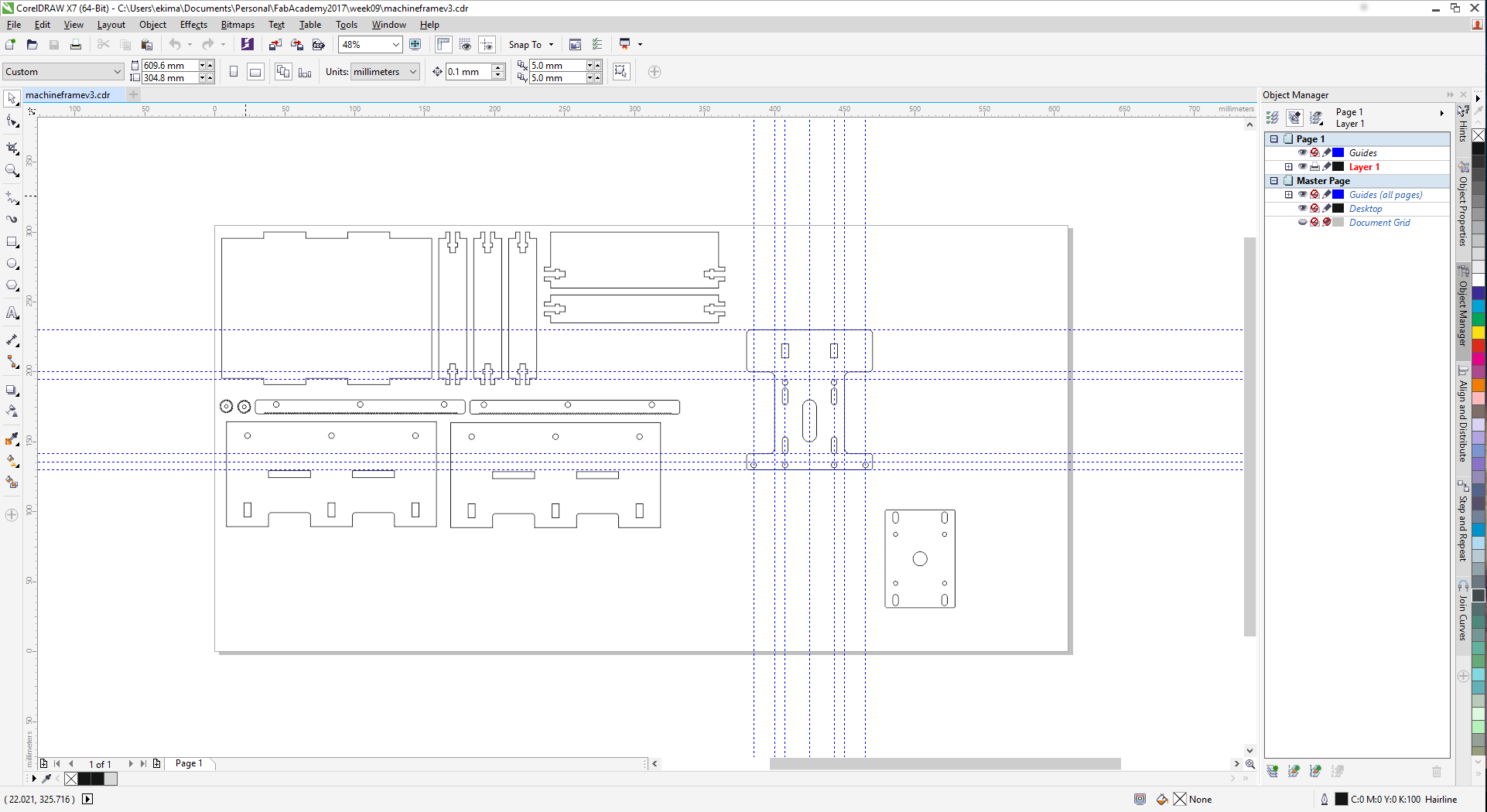
After observing the shopbot, I started with a basic frame in an attempt to get the stability right. I did all the designs on CorelDraw and used the lasercutter to cut them.
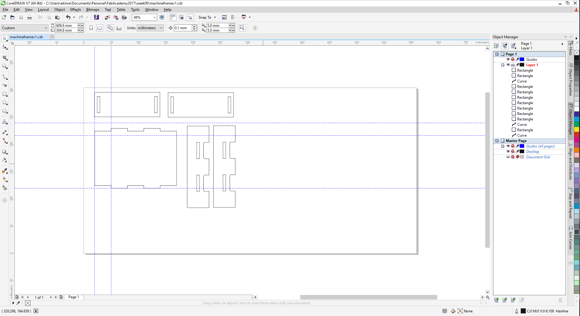
The first version obviously had major stability issues as can be seen...
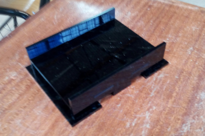
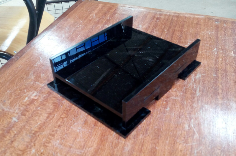
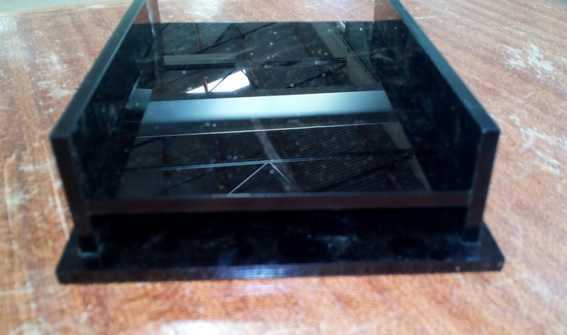
It was painfully obvious that;
- Pressfit was most definately not going to work, something more was needed.
- The addition of leg supports as seen at the bottom was no help whatsoever.
- Drastic re-designing was required to get a stable frame.
At this point I looked around the lab at all our other CNC machines for ideas and that is when this caught my eye;
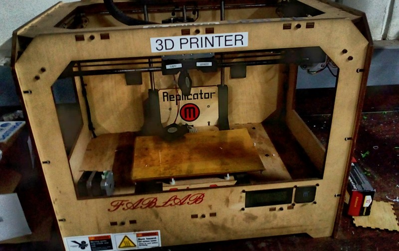
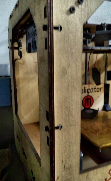
Our Makerbot Replicator 3D Printer and specifically the t-slots as seen up-close;
Design a machine (mechanism+automation), including the end effector
I decided to apply the same principle to my frame. At this point in time I had received the rack and pinion designs from my colleague Derrick and so I incorporated the designs in my design.

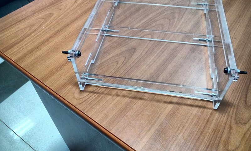
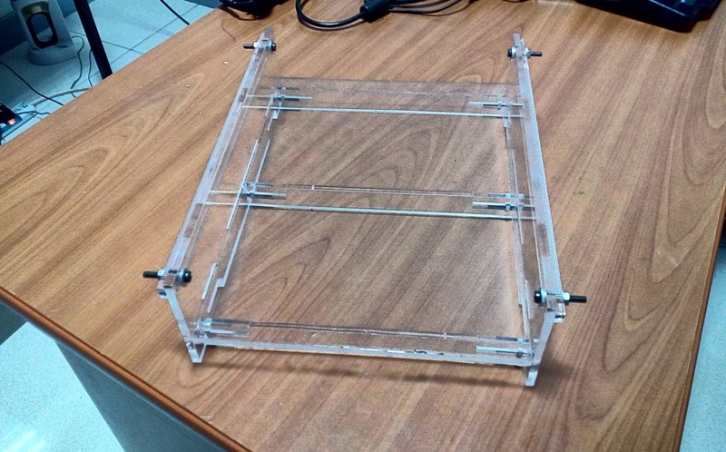
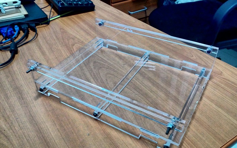
I lasercut the designs and assembled it and this was the result...
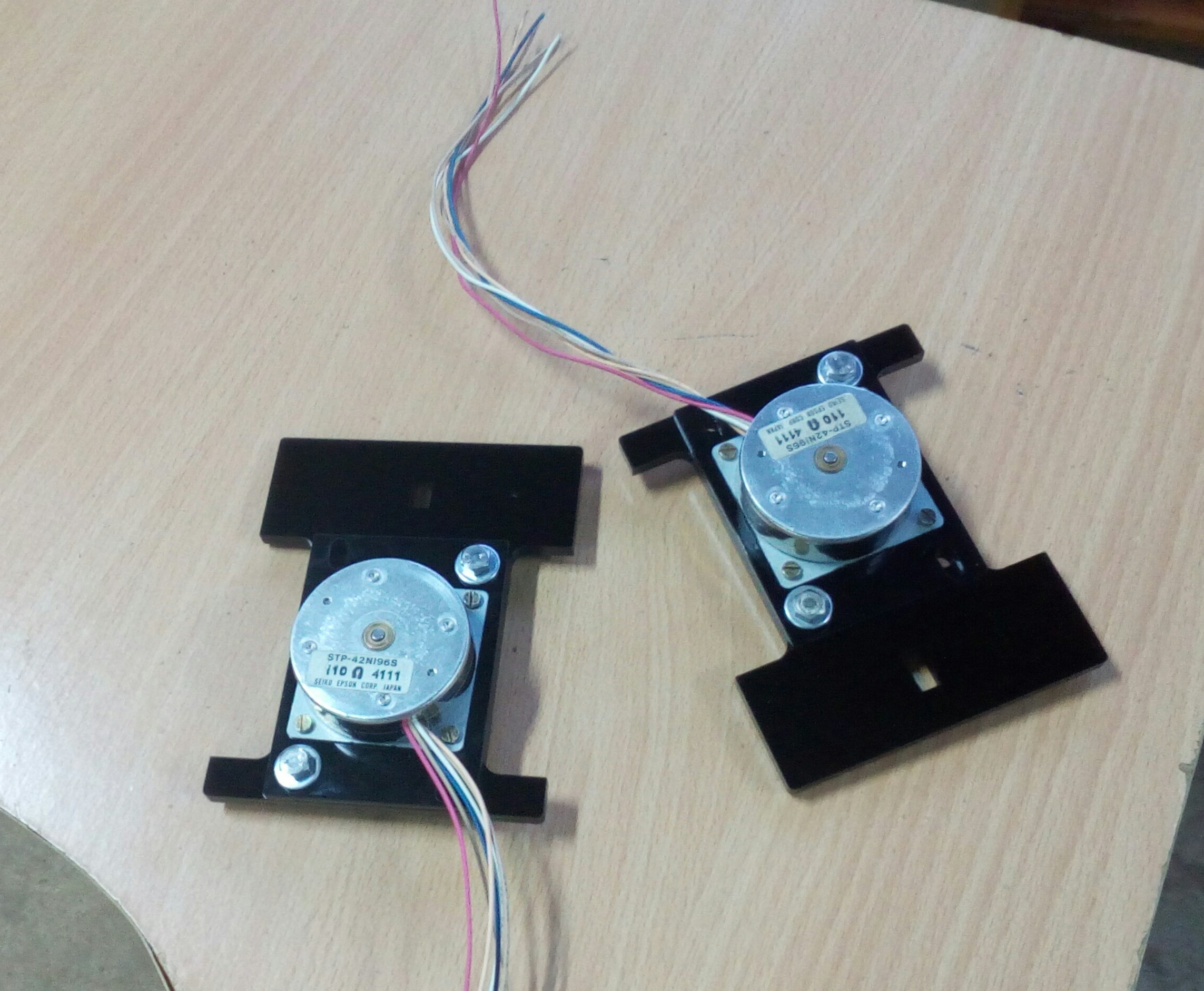
The frame was sturdy and stable and so I assembled the motors and gantry...
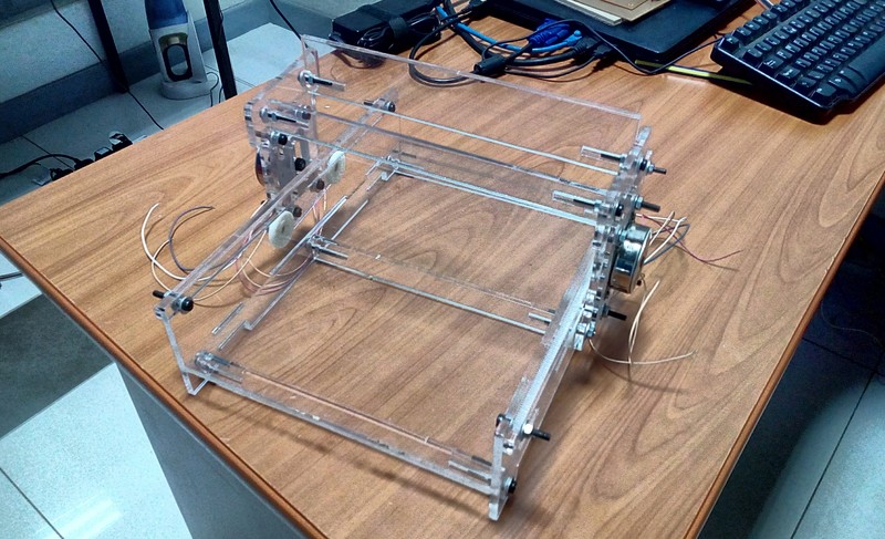
Putting everything together yielded;
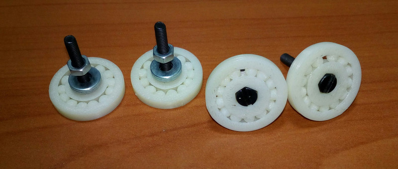
At this point the gantry was quite unstable and I realized that I needed ball-bearings at the ends to stop the motors from swivelling on their axis. The ball-bearings available could not suffice as this was a custom design and as such required highly customized ball-bearings. This meant that the way to fo was to 3D Print the ball bearings.
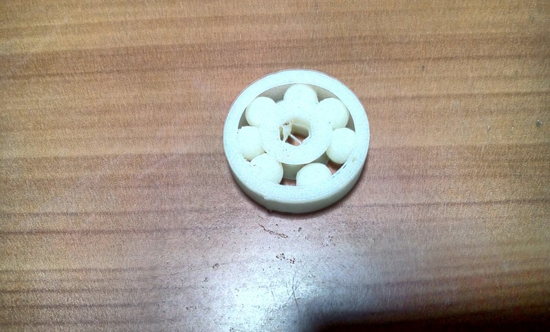
After some research online,I downlaoded a parametric ball bearing generator from Thingiverse which I used to design the ball bearings in OpenSCAD. The process involved in designing the ball bearings was mainly trial and error, with prints where either the balls are fused together;
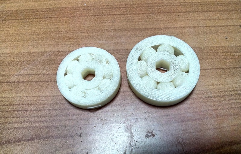
or too small that the balls fall out of the bearing and it gets disassembled.
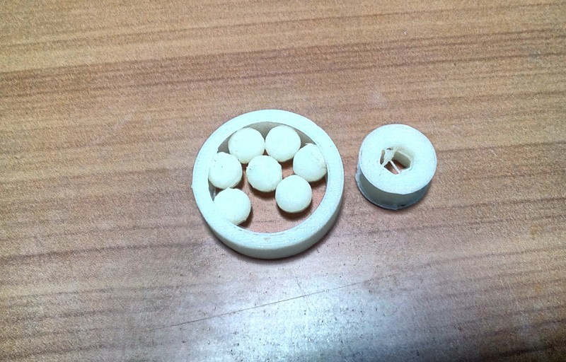
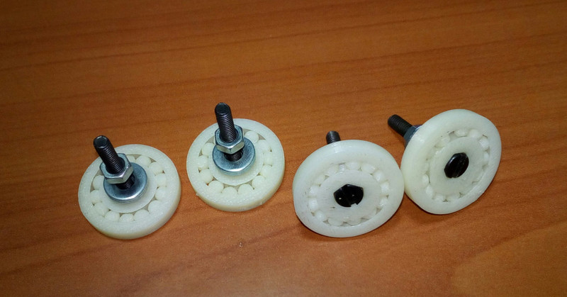
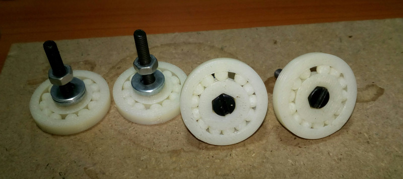
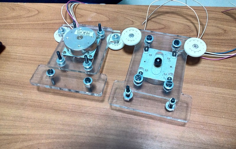
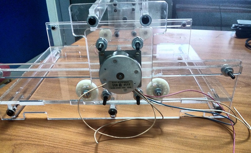
I finally got it right and figured out a way to attach them to the motor frame.
I then went back to the drawing board and re-designed the frame to accommodate the ball bearings.
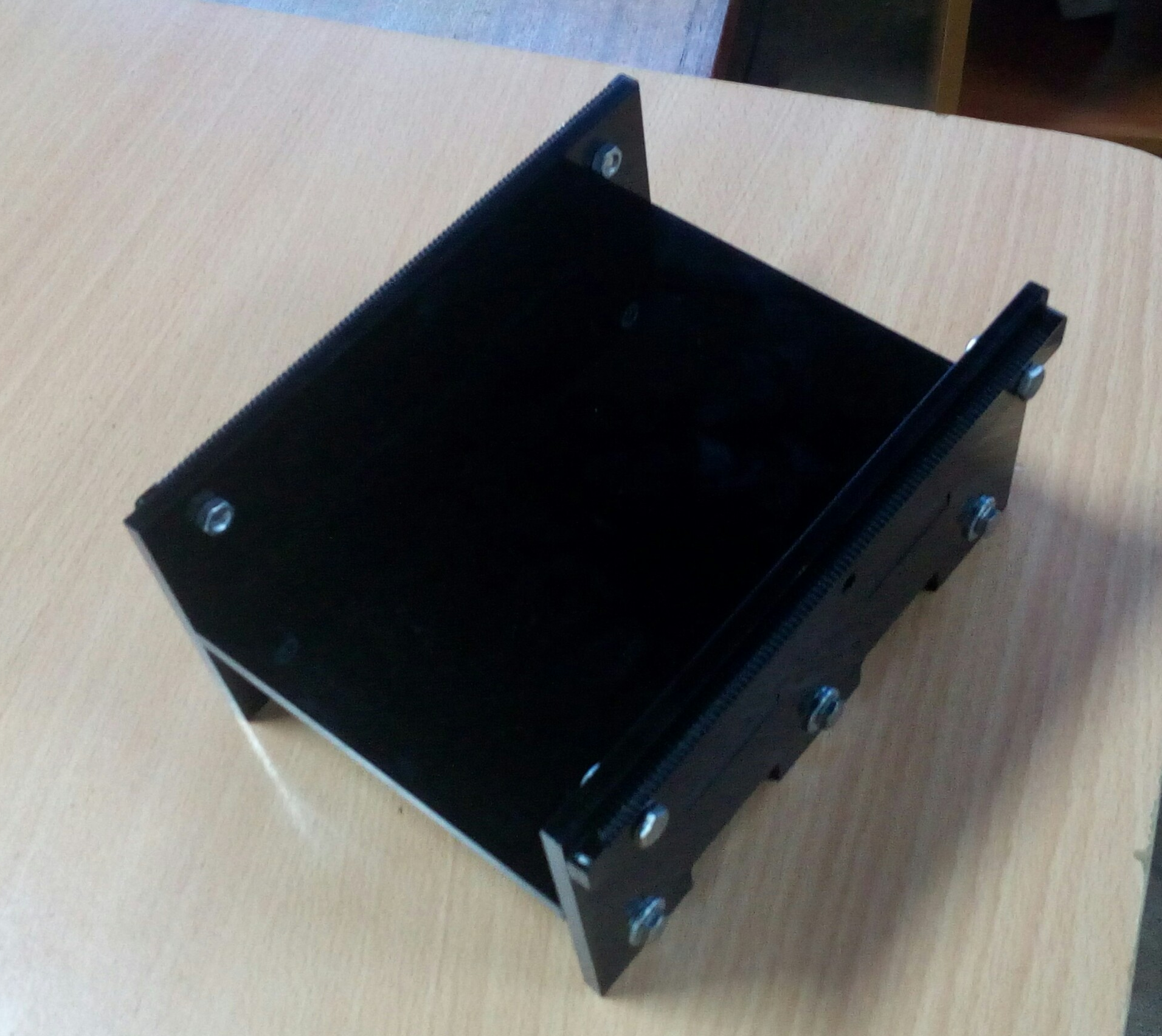
I then cut and assembled the motor holders as this were the only desing changes I had made.
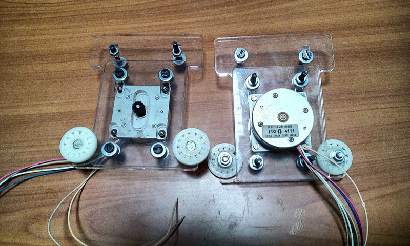
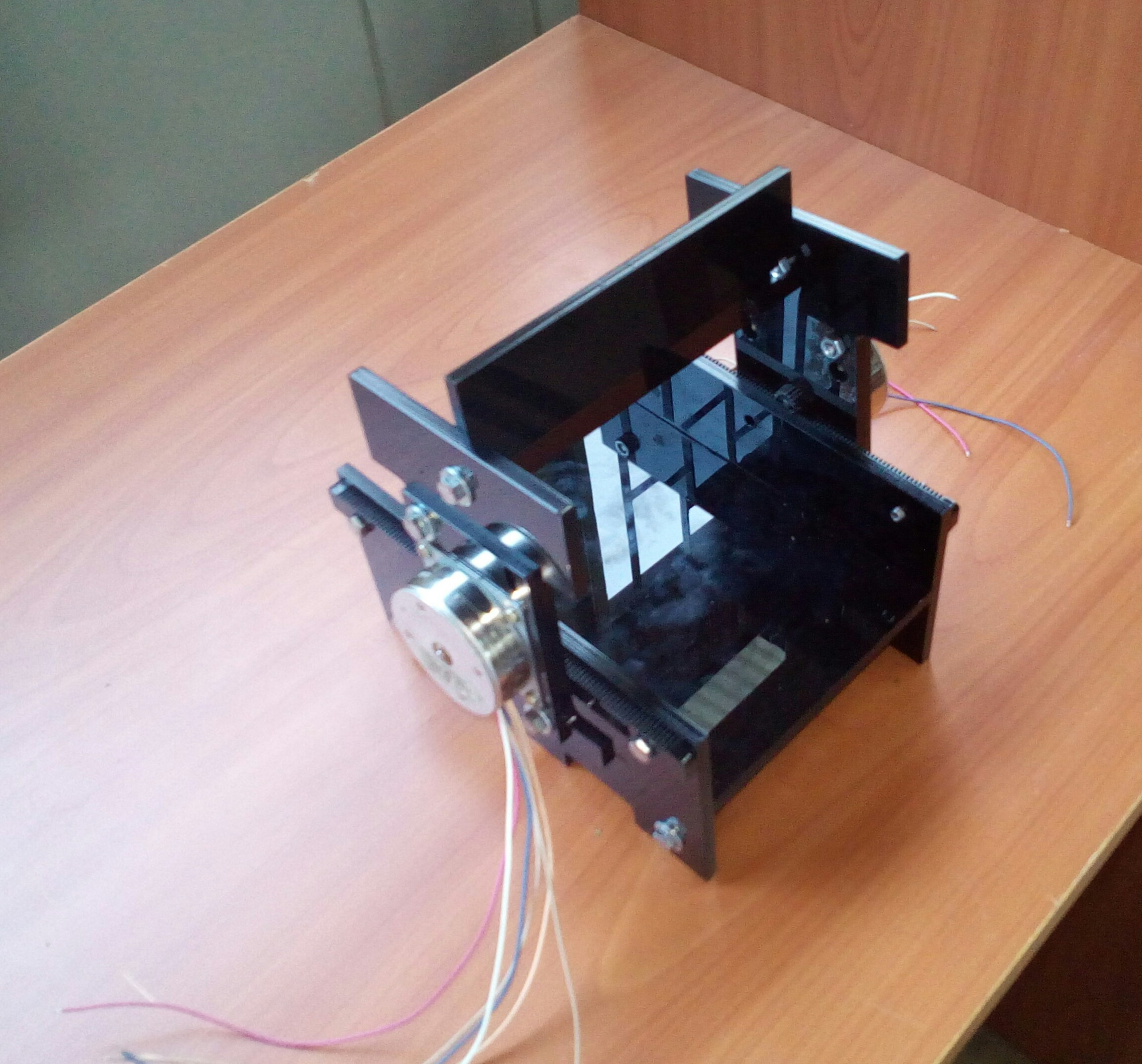
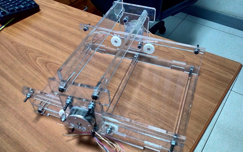
I then upscaled the frame in order to increase the working area, lasercut the frame and assembled it.
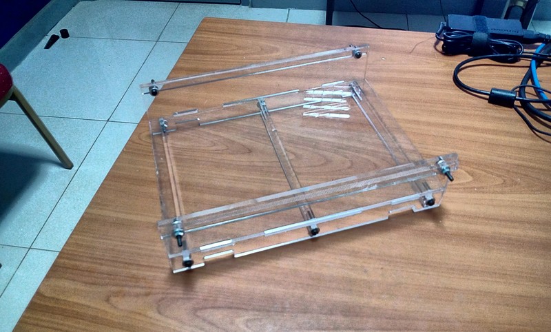
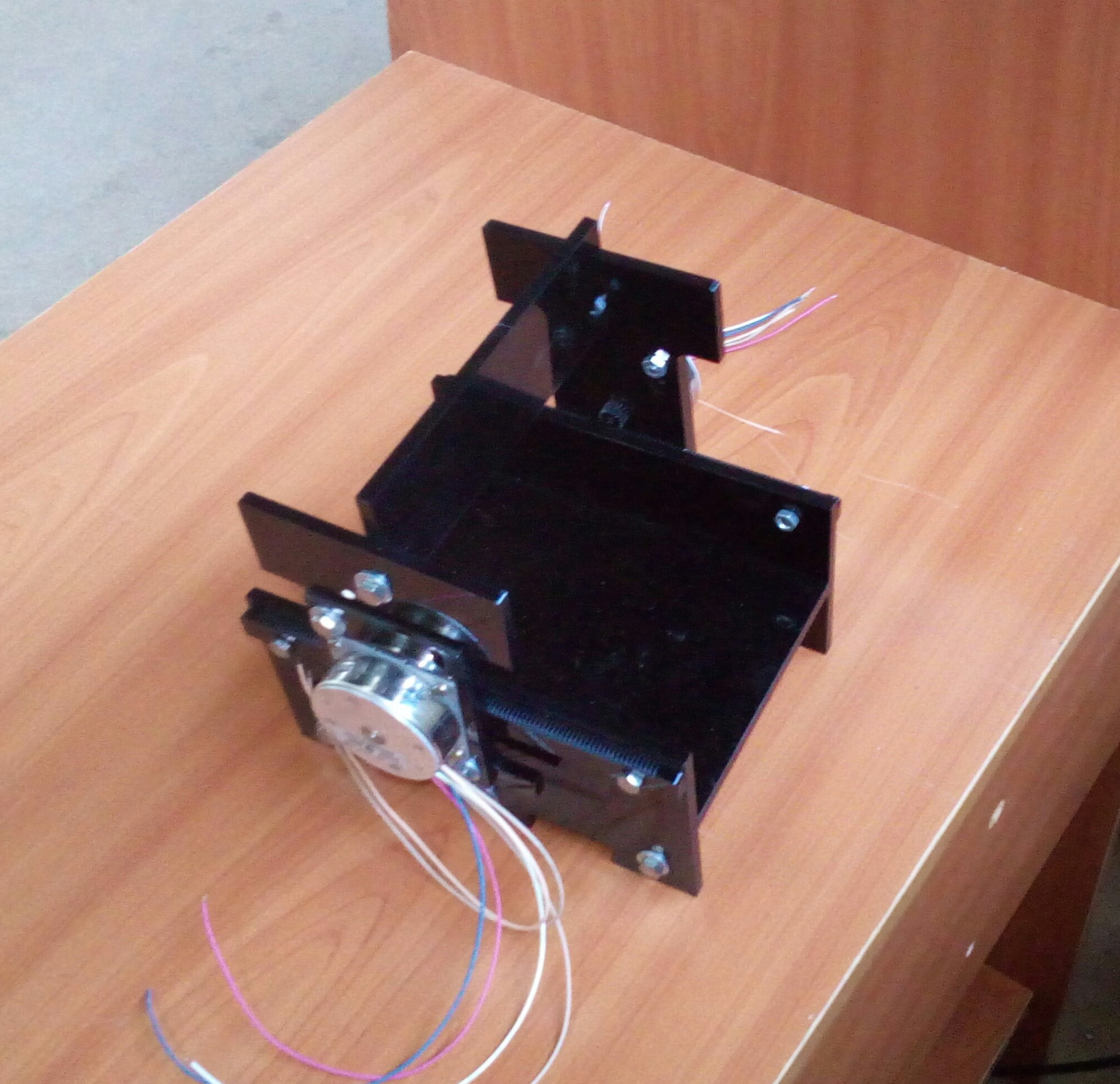
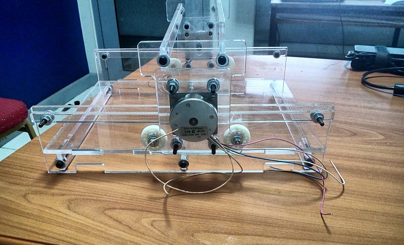
I assembled the gantry in order to test functionality...
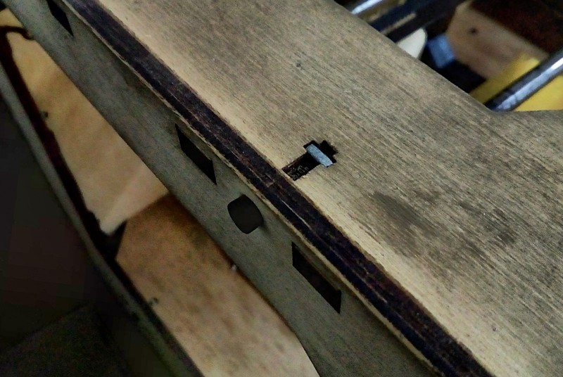
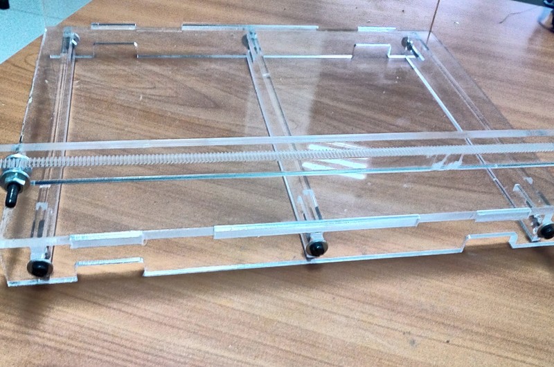
At this point I noted a slight error in the mechanical design. The weight of the gantry was warping the rack as shown in the red circles;
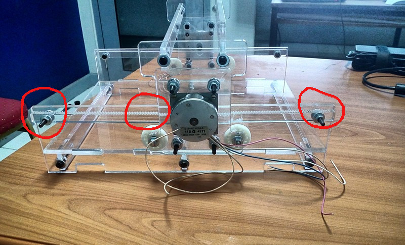
Once I had corrected the errors, I cut a replacement rack that was wider and reassembeled tha machine. I then tested the machine movement by hand as shown in the video...
Assignment wise:
- Design a machine (mechanism+automation), including the end effector
- Build the passive parts and operate it manually
- Document the group project and your individual contribution
Files
Design files for the frame.
Ball bearing OpenSCAD file.