
Electronics Production
Assignment this week, to make an in-circuit programmer by milling the PCB and optionally try other processes.
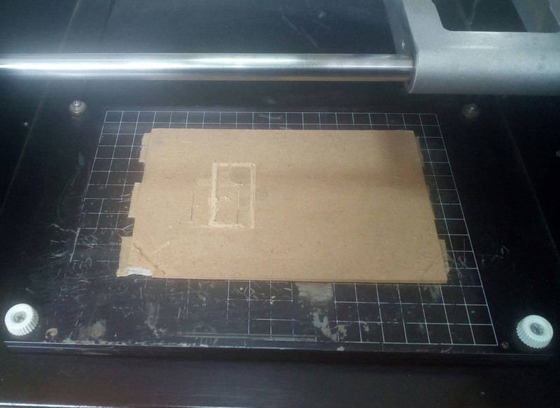
Milling with the Roland Modela MDX20
We haven't used the Modela for some time so it took quite some work to get it working.
First order of business was to get a computer to connect to the Modela. I had two computers available, a desktop running Kali Linux and a laptop running gnome-ubuntu in dual-boot mode with Windows10. Despite the fact that the desktop has a serial port the preference was to get the mill working on the laptop via USB in order to allow fellow students to mill directly.
First order of business, was to get a serial to USB converter that actually works with the modela. These are the ones I attempted;
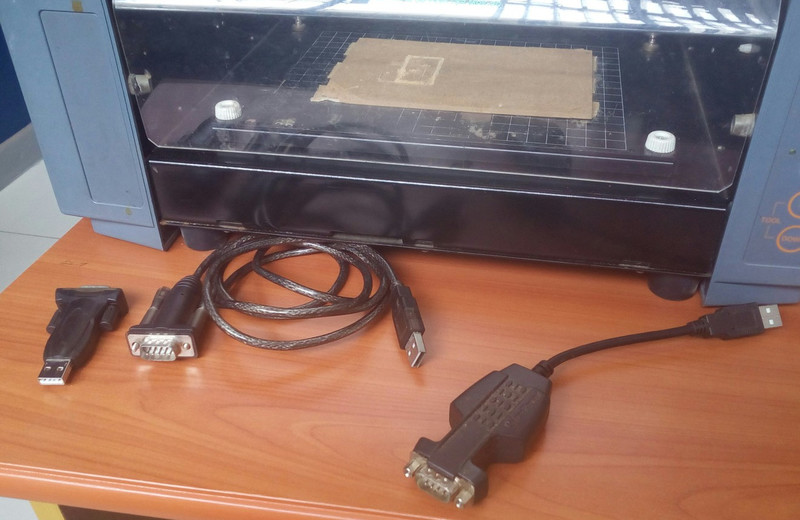
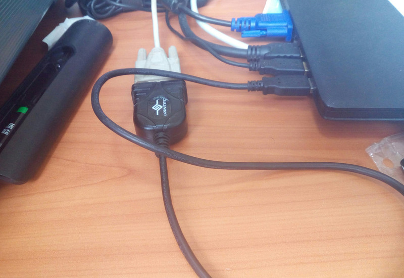
This was the one that worked...
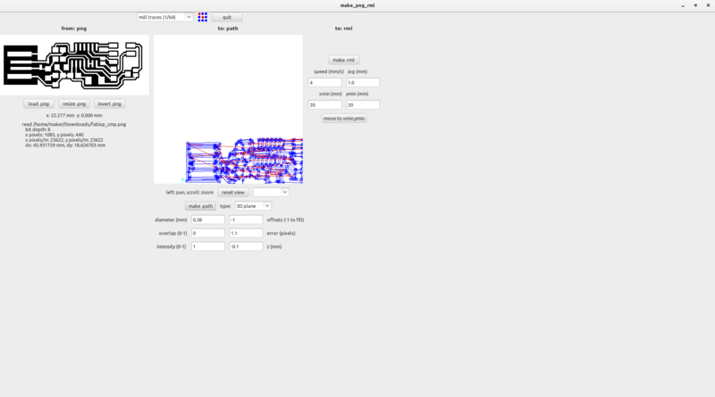
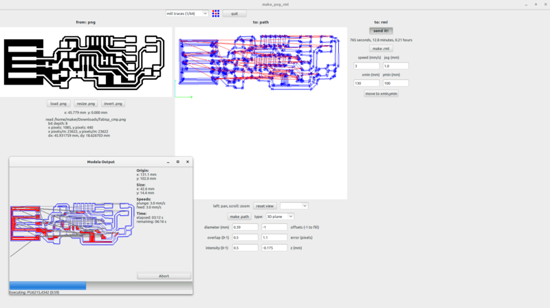
Next up, Fab Modules...
I initially started with the old version of Fab Modules as I had used this version before. I installed this version using this tutorial. Unfortunately, I was unable to send the file to the mill.
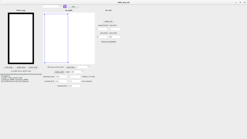
I then followed the tutorial on the Fabmodules github page and installed the new version of fab modules...
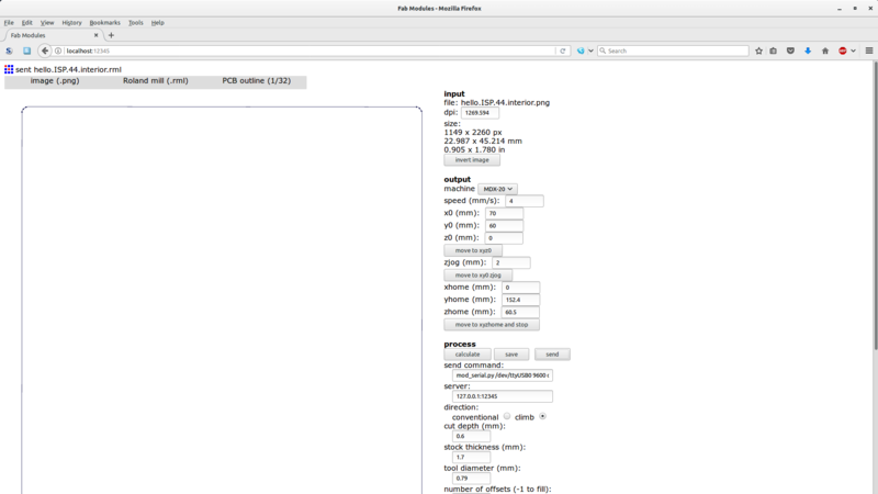
Still no joy sending a design to the mill.
On checking the terminal output on the old fab modules I realised that the issue was with the permissions for the USB device file, /dev/ttyUSB0. I quickly rectified this using,
sudo chmod 777 /dev/ttyUSB0
And, voila...
Next up, was the fabisp and I decided to mill the fabispkey here...
I used,
The result was these two...
Screenshots...
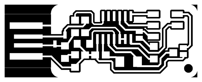
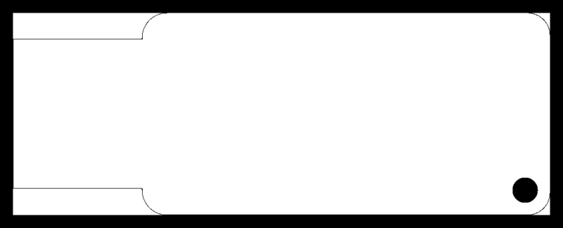
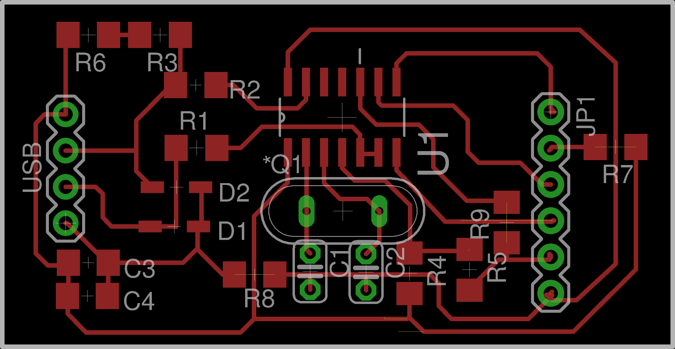
I didn't like how the USB key end required something extra to properly fit and I didn't have any surface mount headers so, I got out my design hat and modified the fabispkey schematic. I came up with a version that allows you to attach an actual USB cable and uses through-hole isp headers.
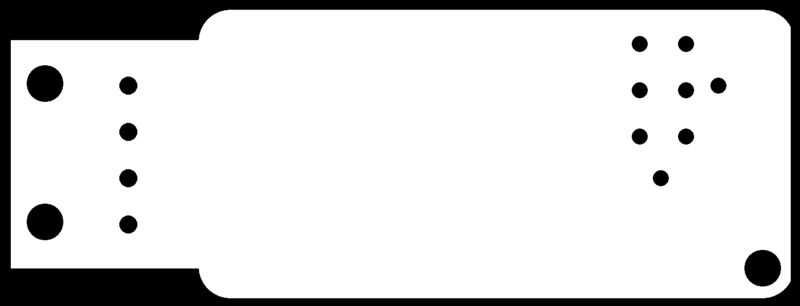
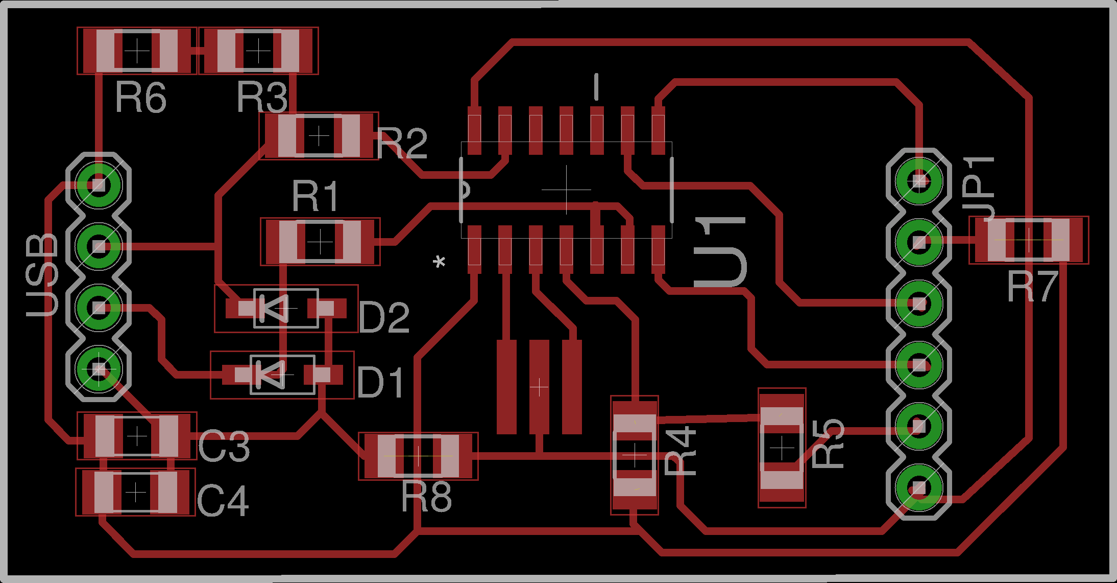
I came up with this..
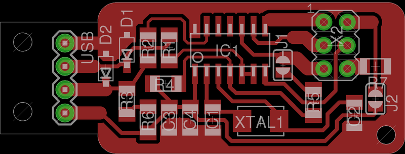
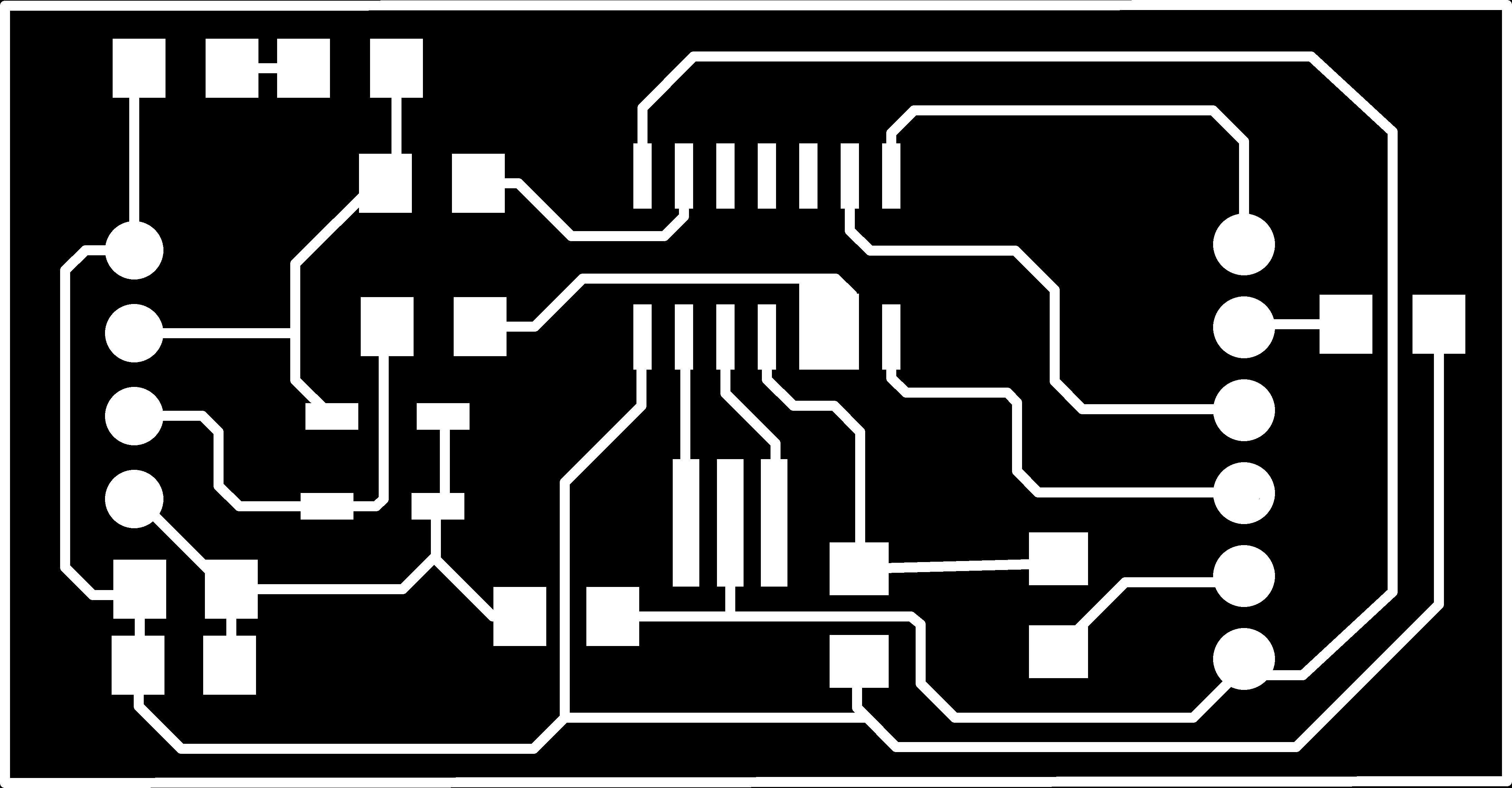
Eagle generated png files...
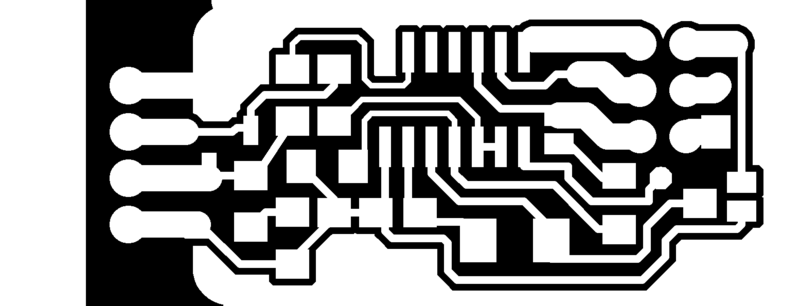
The first and second tries were a fluke, mainly due to a mis-calibration of the z-axis for the 1/32" bit. The first is a result of the machine going into 'view' mode when I accidentally touched the protective cover. The second was simply due to an incorrectly calibrated z-axis...
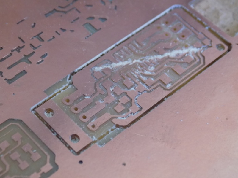
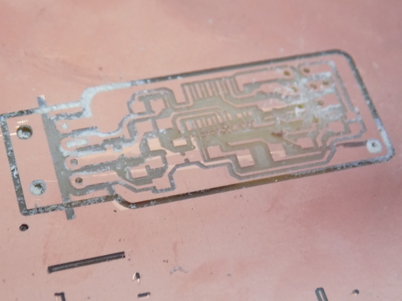
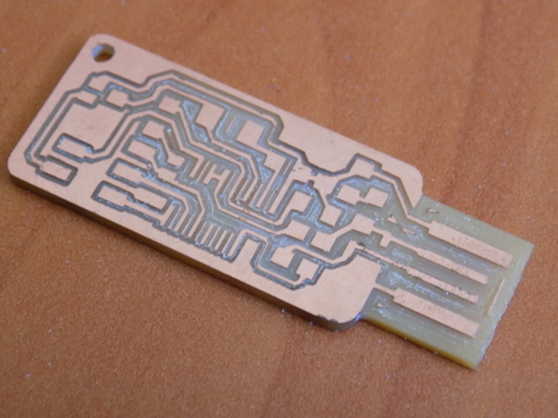
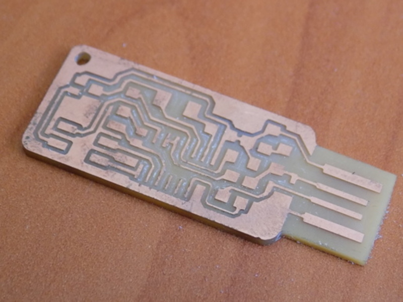
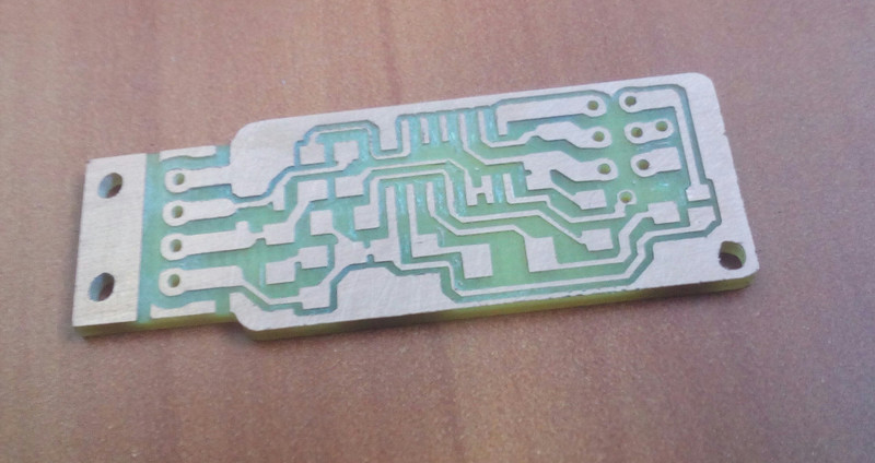
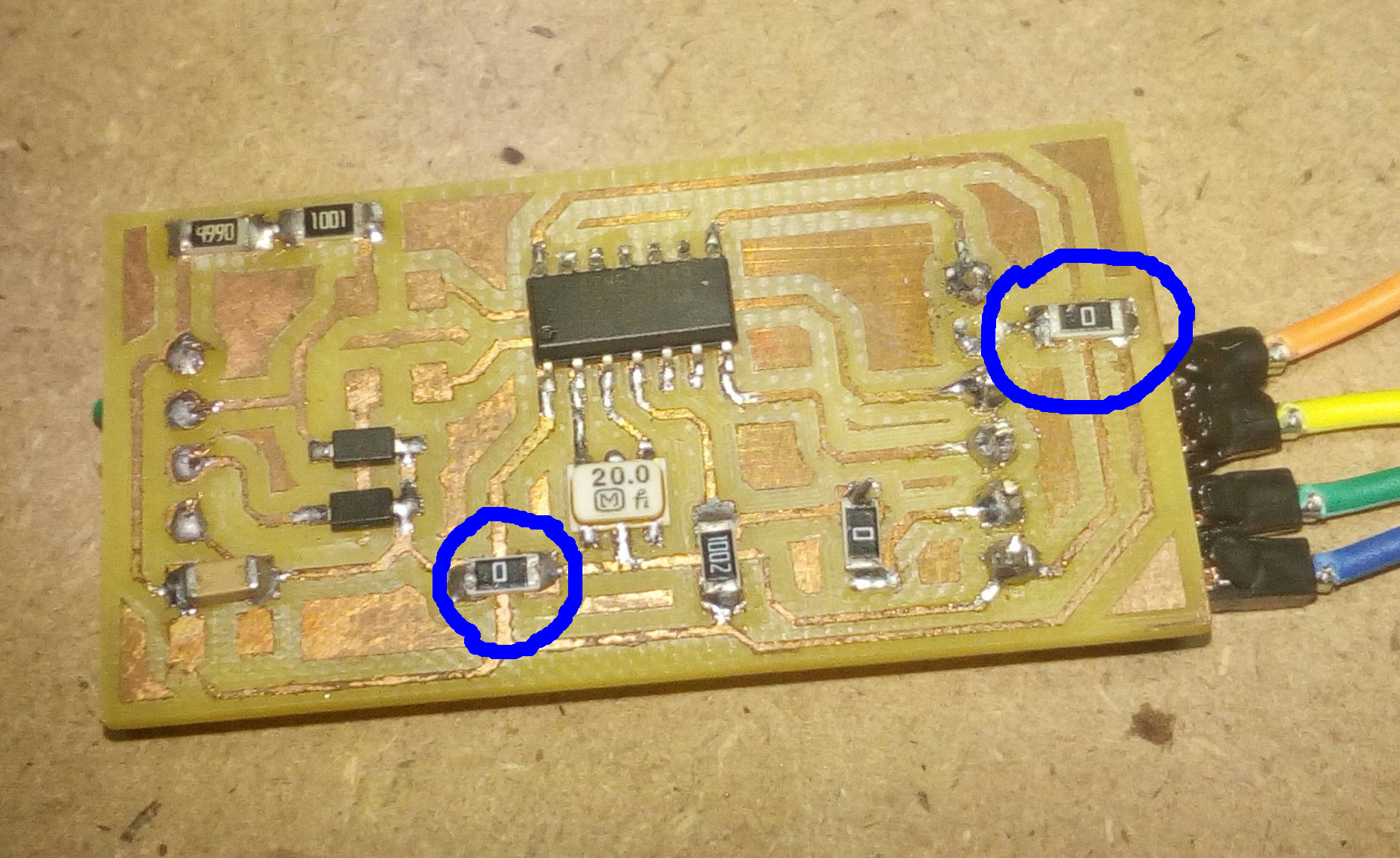
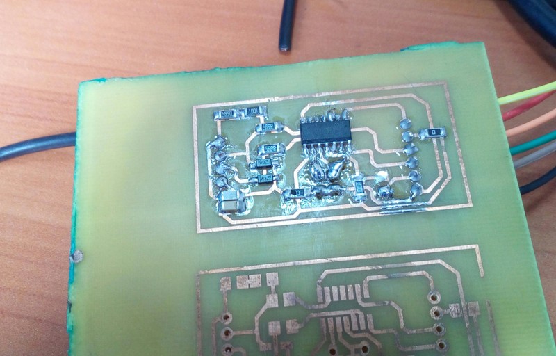
After finally getting it right, this was the final milled circuit.
I mounted the components at which point it became painfully obvious that the design was inelegant to say the least.
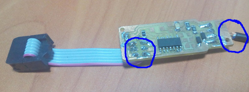
As evidenced by the circled areas, the circuit had a lot of short-circuits especially when the usb and isp cables got twisted.
At this point I then decided that the best approach would be to design the fabisp from scratch. Thus following the tutorial here I started the design afresh.
The first design or version 2, as I like to call it, version 1 being the design based off the fabispkey, also used through hole components for the ISP header and the usb connection.

After milling and mounting the components, while checking for continuity, some errors came to light. Specifically a short-circuit between the GND (ground) and VCC (power) lines.
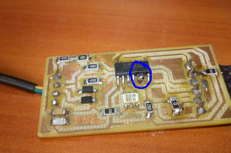
After counter-checking the design I milled another board and did a continuity check before mounting the components. It then became clear where the problem areas were (circled in blue).
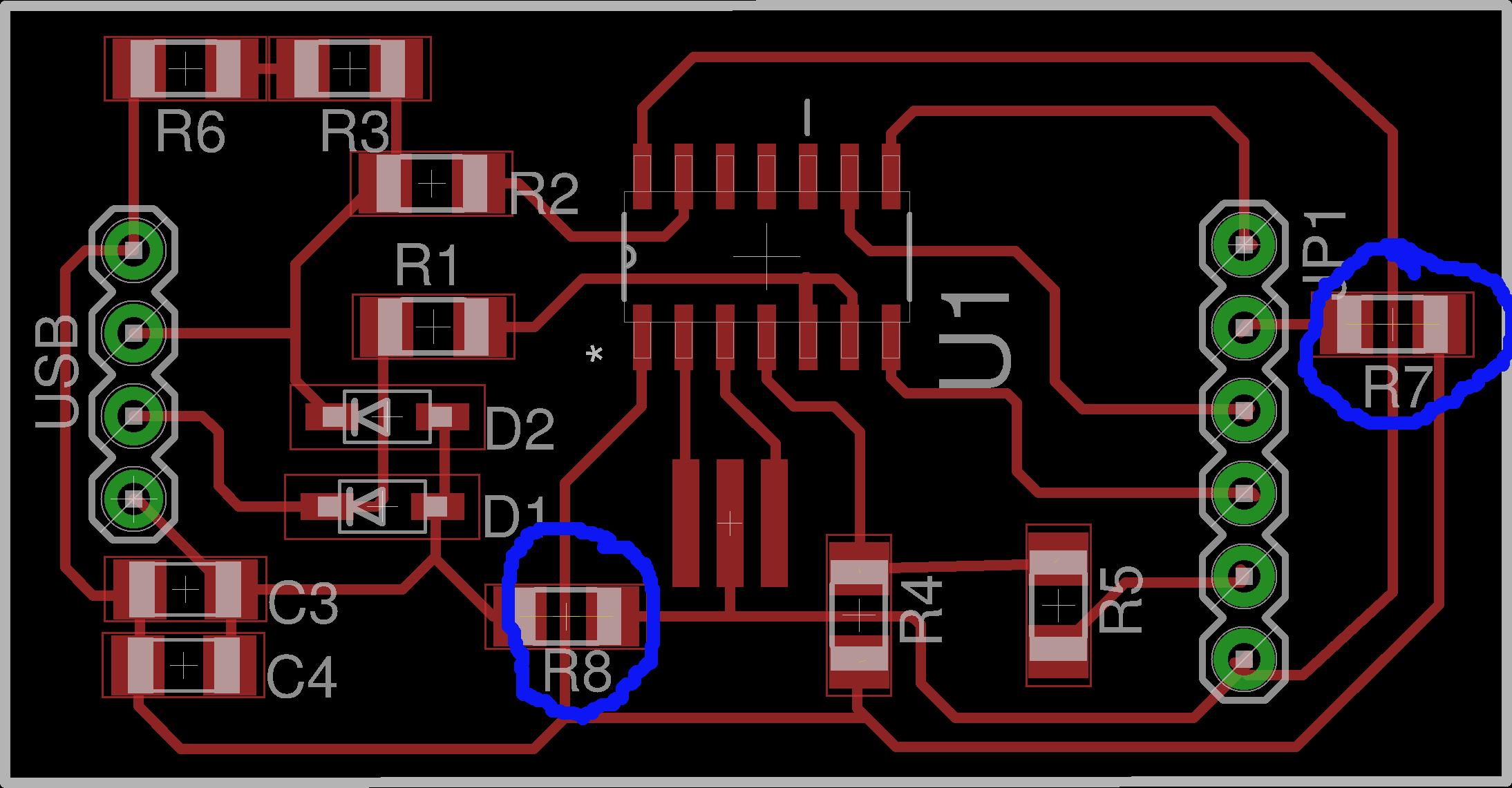
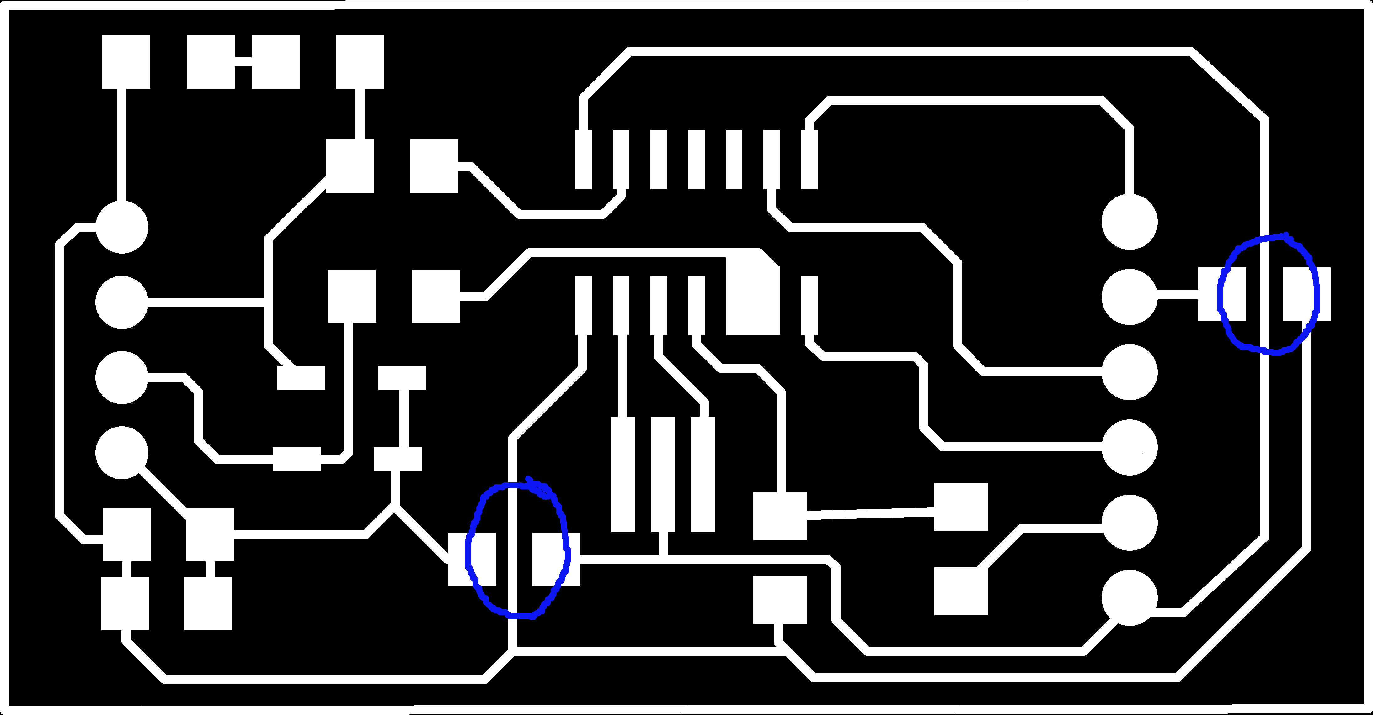
By running a blade edge between the traces in the circled areas, the error was corrected which means that the error occurred during milling. As far as I can tell this is because I was using a 2 flute end mill which has a very rough finish and copper fillings either left over from the milling or still on the traces were bridging the gap between the traces and resulting in the short-circuit.
To that end I ran a blade between all traces to make sure that no short-circuits occurred.
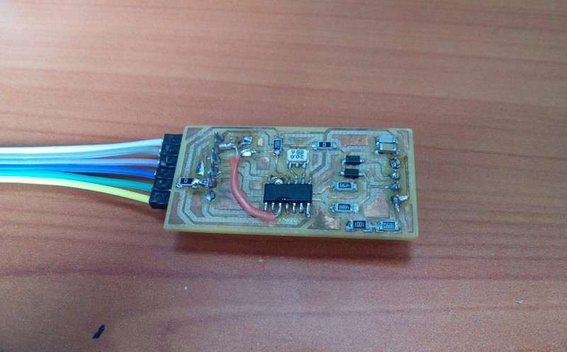
I then proceeded to mount components on the new board. The result...
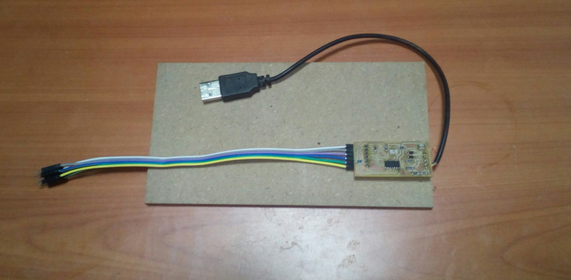
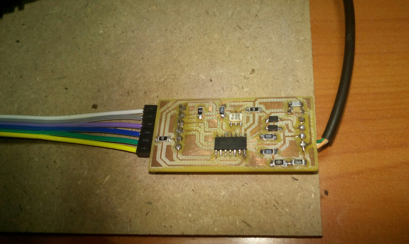
I replaced the isp header with male to male connectors and soldered an actual usb cable.
I then proceeded to load the firmware which was straight forward.
I connected the isp header to the mkII isp header using the configuration as indicated and connected both to the usb2.0 port using a usb hub.

For the programming bit I followed the tutorial here.
On my computer, I first navigated to the folder where I was working from and downloaded the original firmware from the class schedule page using the following command (I was working on a Linux machine)...
wget http://academy.cba.mit.edu/classes/embedded_programming/firmware.zip
Extracted the contents...
unzip firmware.zip
Navigated to build directory...
cd fabISP_mac.0.8.2_firmware/
Cleaned the build files...
make clean
Edited the Makefile for my fabisp which is using an attiny44 and a 20MHz resonator. I was also intending to use an avrmkII programmer so I changed the programmer in the line AVRDUDE = avrdude -c usbtiny -p $(DEVICE) # edit this line for your programmer from usbtiny to avrispmkII so the line looked something like this... AVRDUDE = avrdude -c avrispmkII -p $(DEVICE) # edit this line for your programmer.
So, opening the make file...
nano Makefile
After editing I saved the Makefile with Crtl + O followed by Crtl + X to close it and exit.
Creating files to be uploaded...
make hex
Programmed the fuses...
make fuse
Uploading the code...
make program
The fabisp was successfully programmed. I disconnected the both mkII and the fabisp and plugged the fabisp back in.
In order to check that the fabisp was being recognized, I ran
lsusb
There was no entry for the fabisp which indicated an error and so...
dmesg
The last few lines from the command output contained the error which indicated that the computer was unable to allocate a port for the fabisp as it was refusing connections. Knowing it was a usb error, I went back to the firmware folder and went though the usb configuration file; usbconfig.h in order to confirm that the ports were properly configured and connected.
At this point, this line caught my attention, specifically the note that... D+ should be connected to the interrupt pin INT0.
#define USB_CFG_DPLUS_BIT 7
/* This is the bit number in USB_CFG_IOPORT where the USB D+ line is connected.
* This may be any bit in the port. Please note that D+ must also be connected
* to interrupt pin INT0! [You can also use other interrupts, see section
* "Optional MCU Description" below, or you can connect D- to the interrupt, as
* it is required if you use the USB_COUNT_SOF feature. If you use D- for the
* interrupt, the USB interrupt will also be triggered at Start-Of-Frame
* markers every millisecond.]
*/
Since the D+ line was connected to pin 6 and the interrupt pin INT0 was on pin 5, I simply ran some solder over the two pins to short them out.
And that solved the usb error. In order to test the isp's programming capability, I connected the isp to an arduino and ran the basic avrdude command...
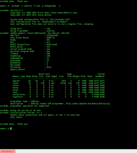
avrdude -c usbtiny -p atmega328p
The result was the following error...
avrdude: programmer operation not supported
avrdude: Setting SCK period to 10 usec
avrdude: initialization failed, rc=-1
Double check connections and try again, or use -F toverride
this check.
avrdude done. Thank you.
I ran the same command with -b option so as to vary the SCK period to no avail.
I then ran the same command again only this time with the -v option in order to get a verbose output that would be helpful in determining the cause of the error. The result...
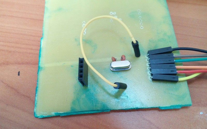
The initial thought was that the problem was with the resonator and so I redesigned the circuit with a crystal and two 22pf capacitors. Since I did not have the surface mount versions available, I used through-hole components. The crystal I had available was a 16MHz crystal.
For this version I decided to chemical etch the circuit. The chemical we use to do this is Hydrogen Peroxide and HydroChloric Acid. Information on how it works can be found here.
I printed out the circuit on art paper, which is paper with a glossy finish using a laser printer. I then used an iron box to transfer the toner onto a copper-clad board. This method, called 'toner transfer' is well explained here.
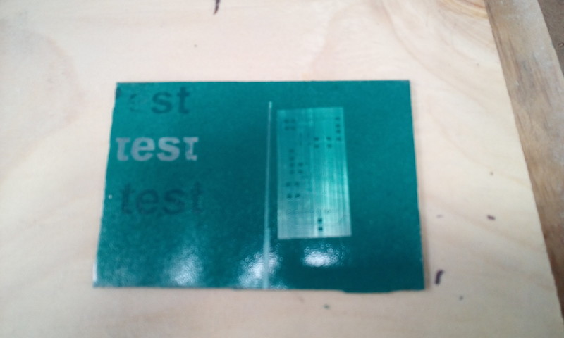
At this point I did a little experimentation with the laser-cutter and spray paint in an attempt to find an alternative to using the 'toner transfer' method.It didn't work out so well, as evidenced...
Once the etchant was done, I cleaned the board and mounted the components.
I loaded the firmware and tested it and still no joy. I had of course, edited the Makefile to reflect changes in the circuit i.e. the frequency
At this point I double-checked the fuses and found that they were okay so I decide to double-check the circuit. With my previous mistake in mind, I crossed check my circuit connections with the circuit explained by the tutorial I had used to design the circuit. At this point I realized that a connection to the reset pin was missing.
To correct the error, I drilled two holes and soldered on a connector.
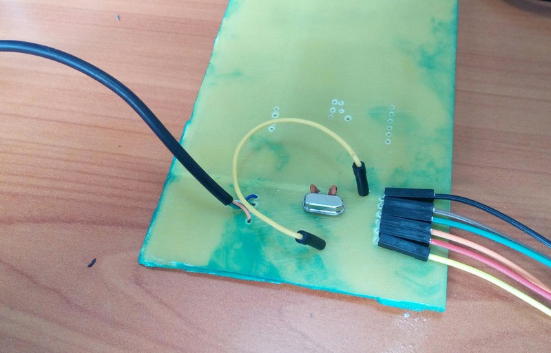
Finally, the board worked like a charm.
I made the same corrective soldering on the other board as shown and it also worked without any problems.
On running the command;
avrdude -c usbtiny -p atmega328p -v
with the fabisp connected to an arduino, I received the following output...
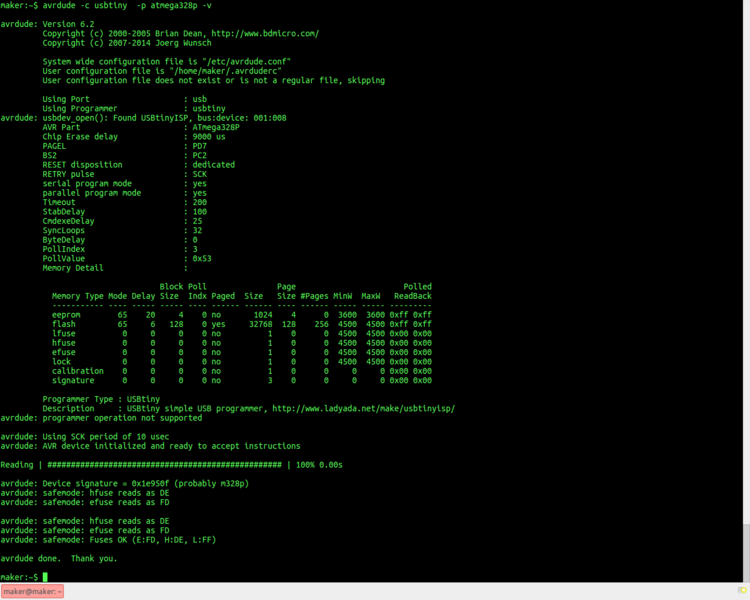
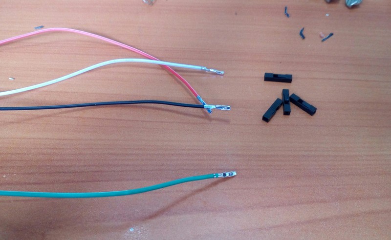
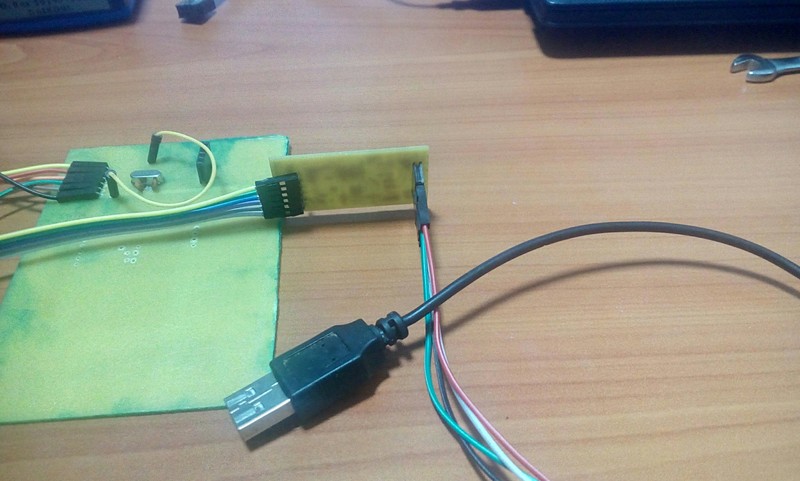
Once I had gotten the fabisp's working, I made one more change. Since I had only one usb cable, I de-soldered it from the board and made it into a connector by soldering its wires onto the female side of 4 male to female connectors. I then soldered female headers on the usb side of the fabisp's thus allowing me to use the usb cable for other projects. Pictorial on how I did this below...
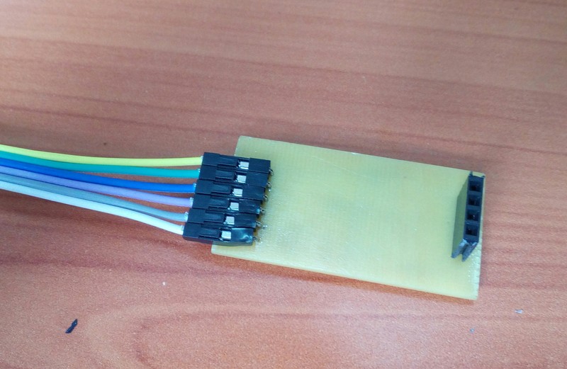
Female headers on the isp's
Modifying the usb cable and the connectors..
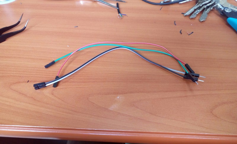
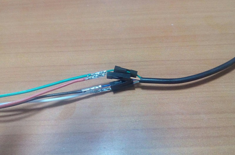
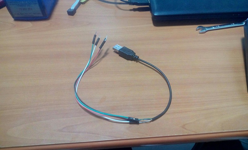
Final cable and connection...
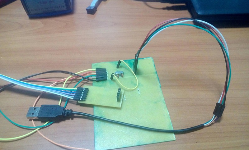
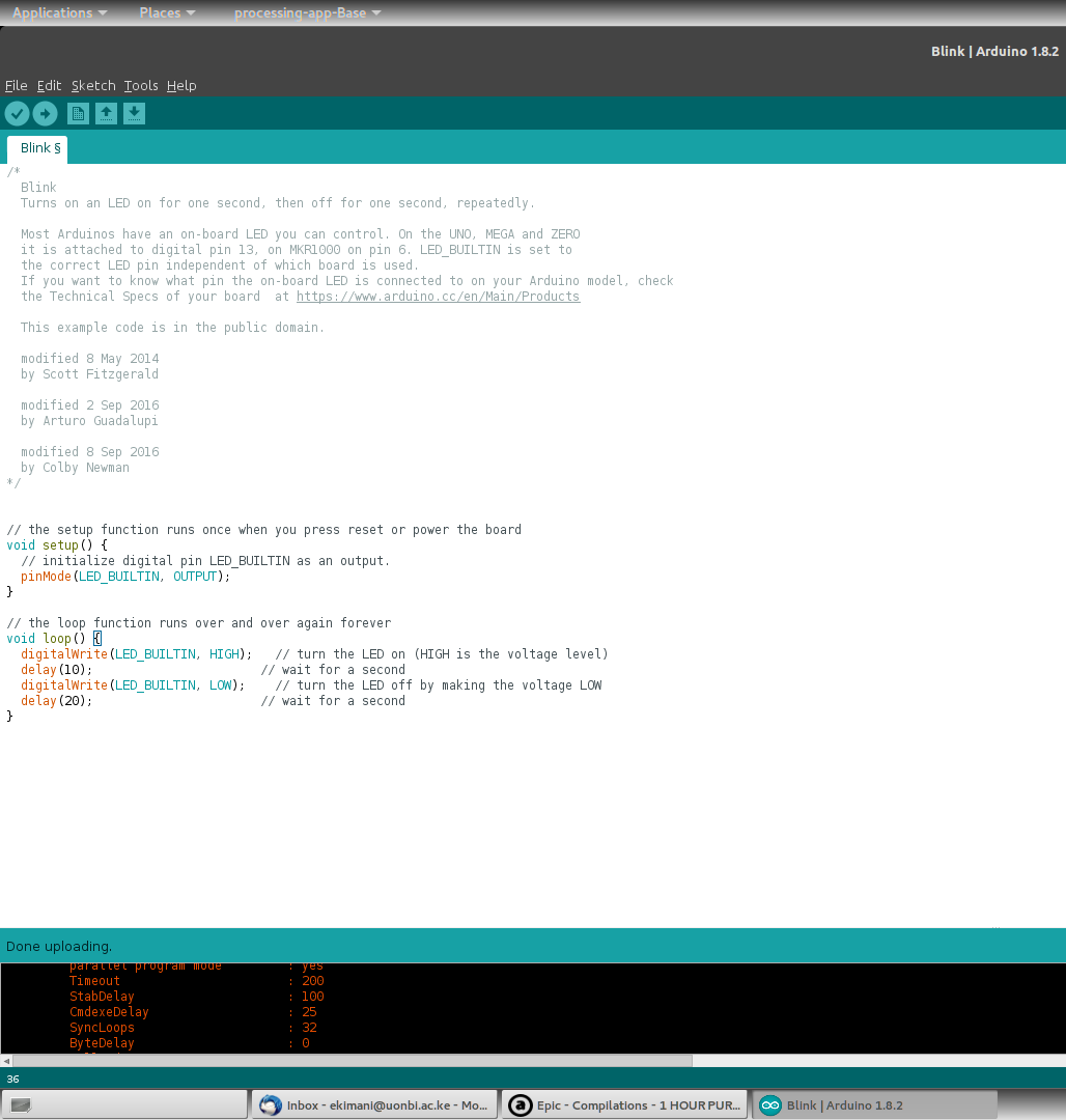
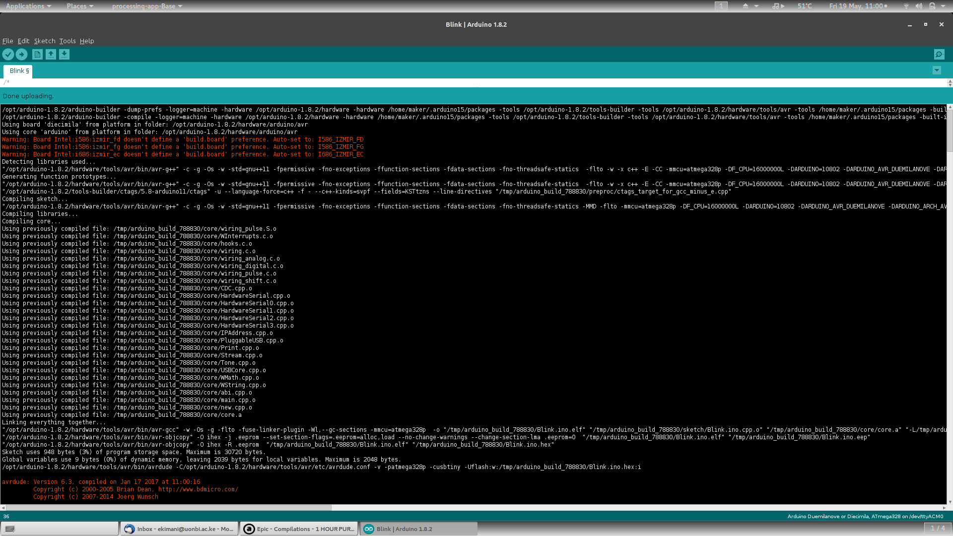
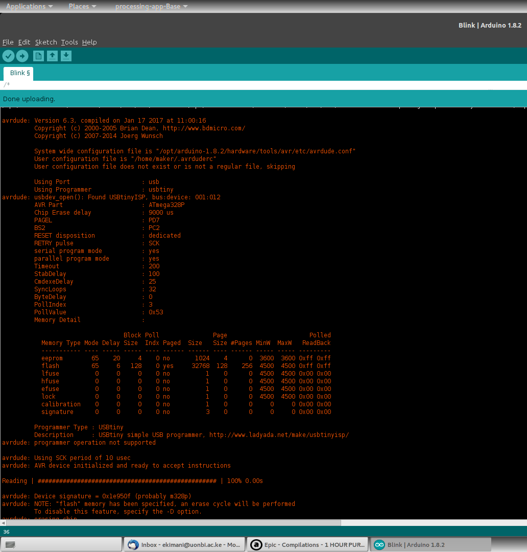
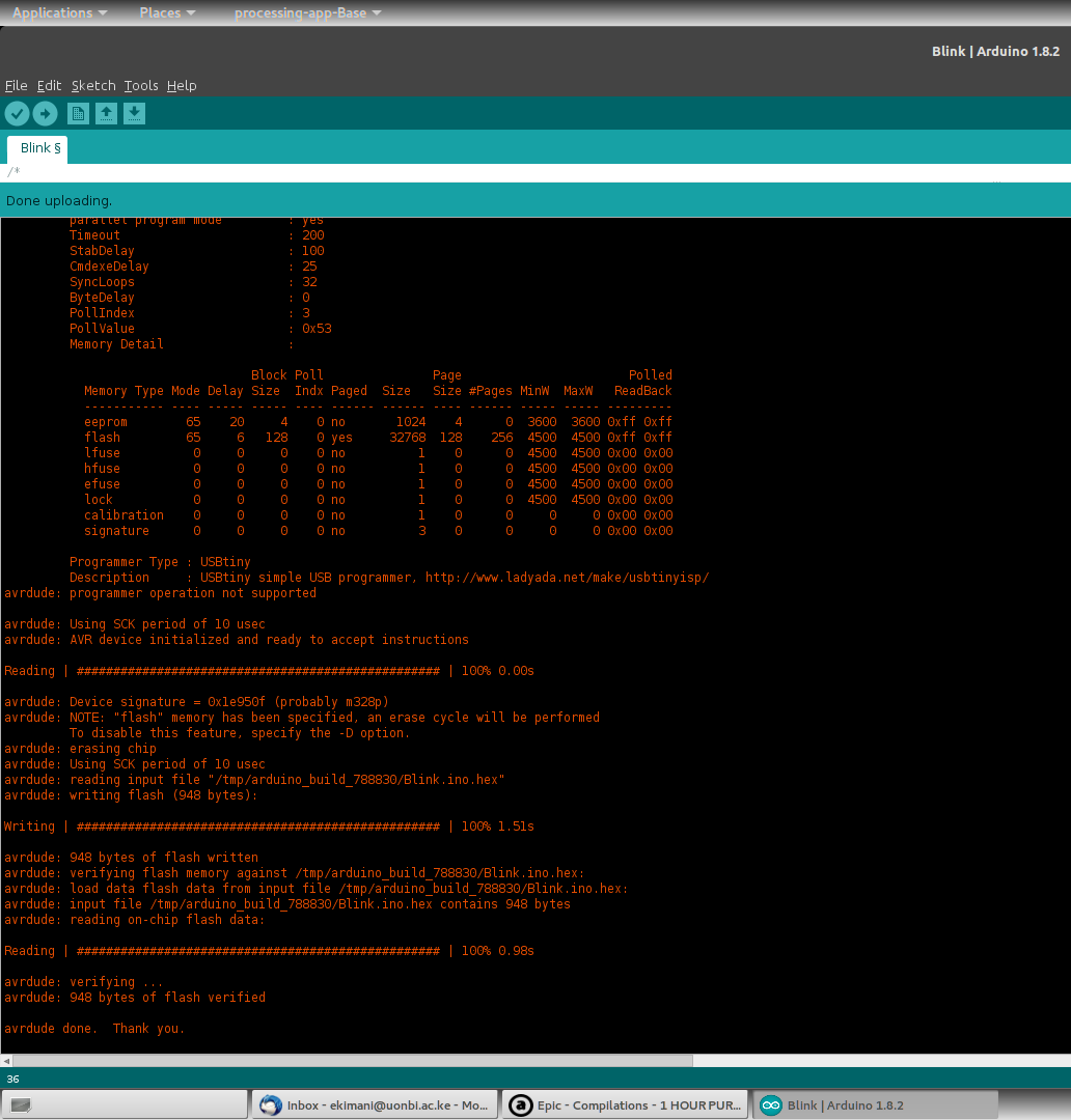
In order to test the two isp's, I uploaded the 'Blink LED' example code to an Atmega328p I had lying around using Arduino IDE's 'Upload using Programmer' option. The Arduino IDE verbose output is captured in the screenshots below.
I took some videos uploading different 'Blink LED' codes to the microcontroller using both fabisp's.
Assignment wise:
- Make an in-circuit programmer by milling the PCB
- Try other processes (optional)
Files
Original fabispkey files
My version of the fabisp files
- Fabisp my resonator version Schematic
- Fabisp my resonator version Board
- Fabisp my crystal version Schematic
- Fabisp my crystal version Board
Firmware: firmware.zip