Final project Index:
Concept:
-My project will consist in an anti-run over security enclosure. The last accidents and terrorist attacks, produced in crowded areas,
makes necessary to protect public important spaces from possible accidents.
Around a circle or a square we will prepare a safety zone,
when people it's walking the security sistem is not activated but when a car or a heavy vehicle cross the detectors with high speed the security system it's activated.
avoiding the collision that may be caused, could thus be an urban prevention of accidents or terrorist attacks.
--- How does it works? ---
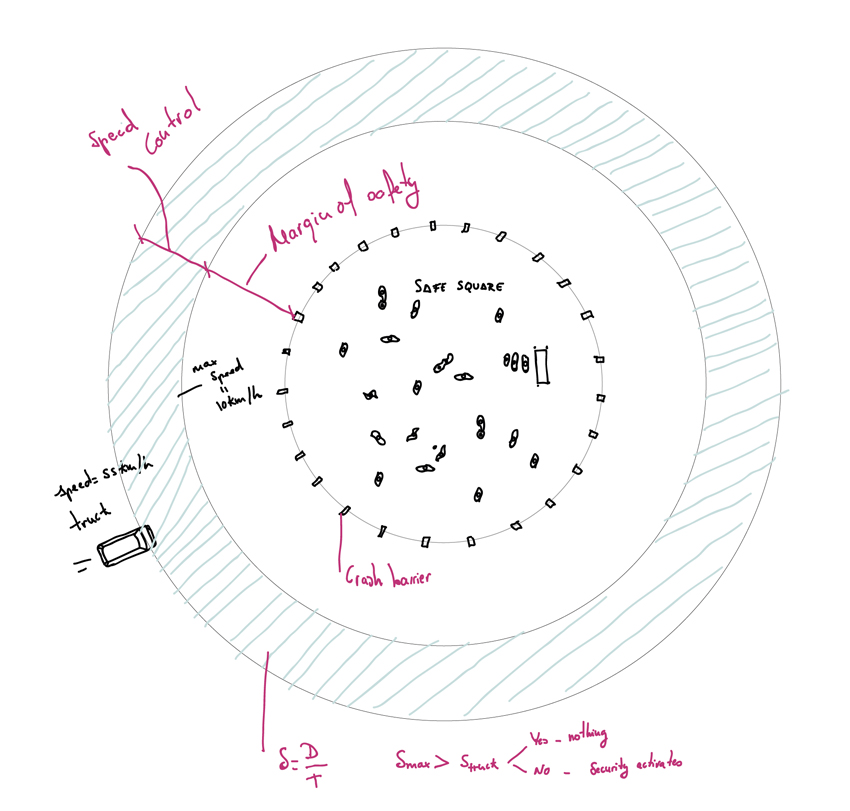 Safe Square and zones.
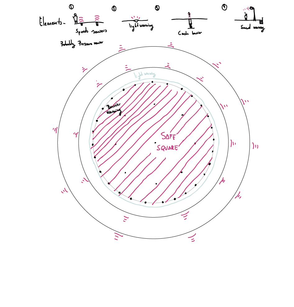 Elements and devices.
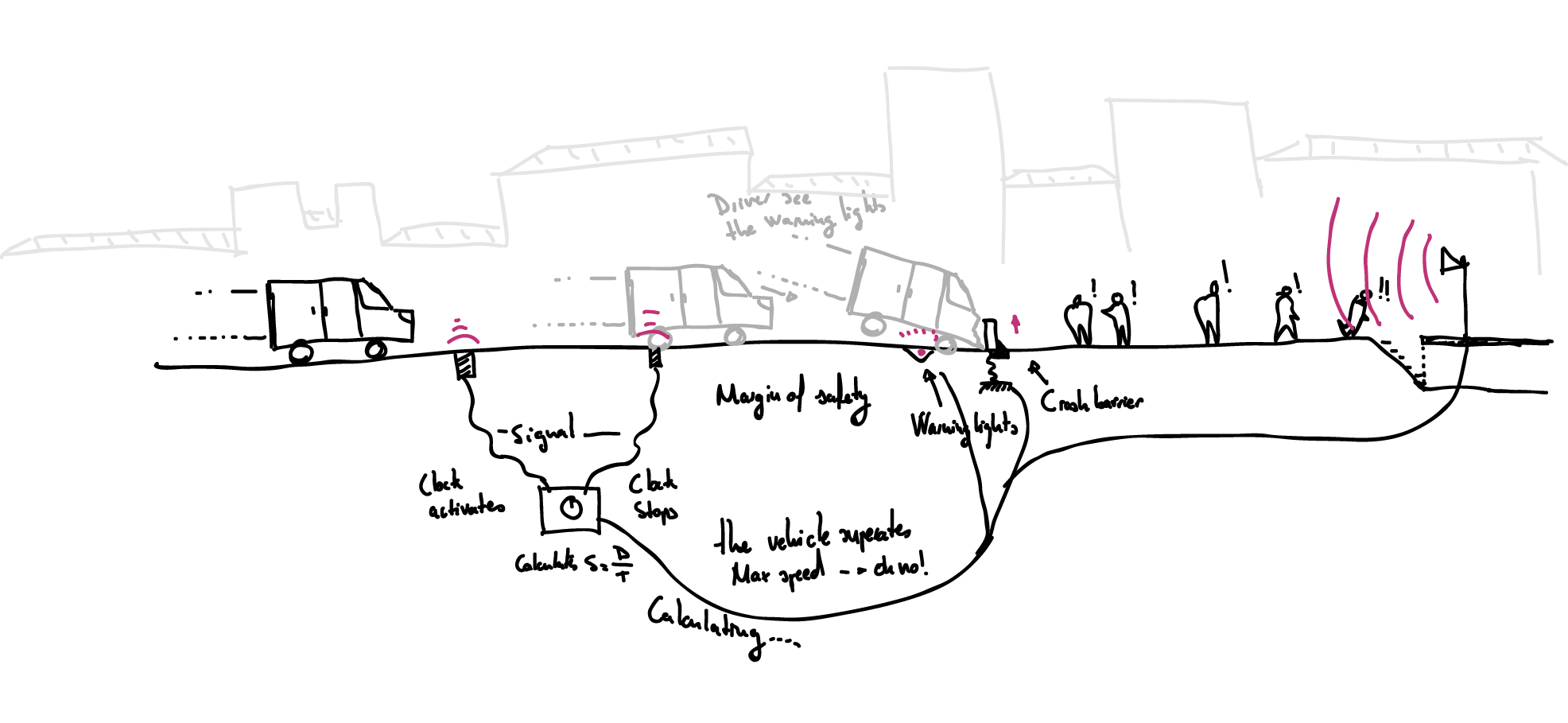 How does it works?
This will be an initial phase of the project, and in the future we will be able to make it more complicated or more simple
Update:
briefly summarises your project
This is the presentation of my project that I included in the James Dyson awards contest.
What It Does?:
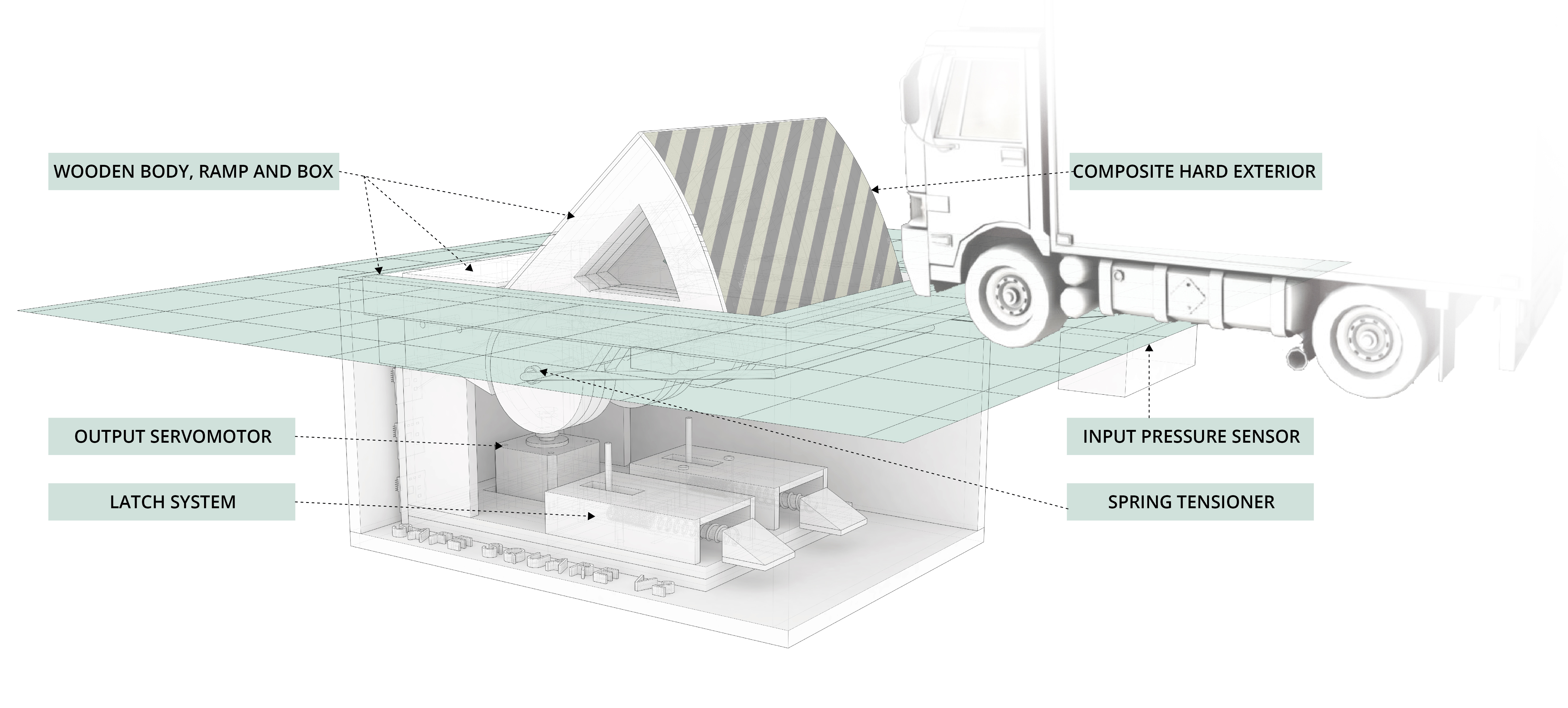
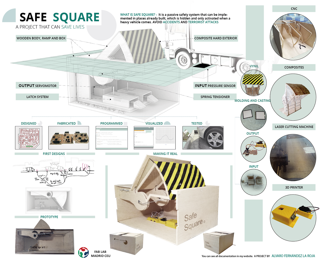
My project is a device designed to be place in the plazas or main squares of cities in order to avoid accidental run-overs and terrorist attacks like the ones thar occured in Nice or London. It is an automatic bollard that rises when it detects a high weight.
The Inspiration
The inspiration came from the latest attacks in numerous countries where a heavy vehicle was used to attack pedestrian friendly zones. These frequent attacks have raised awareness for taking measures to ensure safety within these popular areas of the city. These type of attacks have been increasing and there is no doubt solutions have to be made in order to prevent them from happening again.
No adequate solution has been made and the city halls have only thought of placing large objects that do not take into consideration the general transit or the sensation of fear; these solutions are not the most adequate.
How It Works?
The operation is similar to conventional bollards where there is a resistant element that absorbs the kinetic energy of the vehicle and resists the impact, but in this case, there are some differences that I explain below.
It is hidden and integrated with the pavement.
It has a spring system which rises when the micro-controller sends the signal.
It has a pressure sensor, which only activates when it detects a heavy weight (a vehicle) and does not activate with people walking by or passing over it. This sensor sends a signal to the micro-controller that moves a small motor that releases the spring and lifts the bollard very quickly.
The sensor can be adjusted. The connection to the micro-controller and the motor is through serial networking and the frequency inhibitors do not affect it.
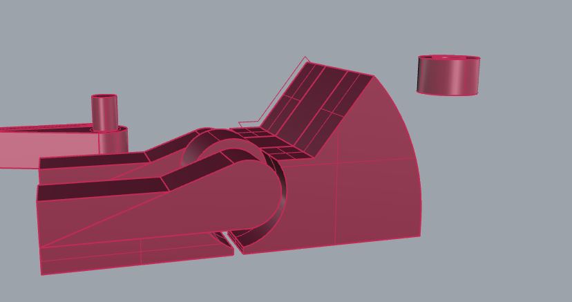
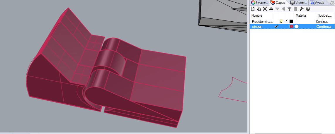
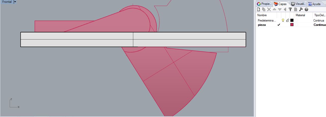
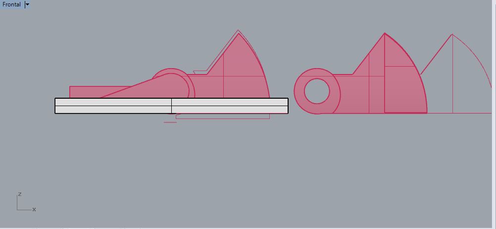
The bollard is shaped like a ramp and acts as a hinge, when it is hidden is at ground level. It is made of steel and the shape of the ramp helps to dissipate the energy.
Stages of Development
The project has been researched in parallel within the fields of design, electronic prototyping and programming.
The first step was to perform a study on this type of elements and to sketch the general proposal, then I made the 3D design of the first version. The purpose of this era was to verify that it could function mechanically, I made a prototype using MD wood with a machine laser cutting, a spring inspired by a mouse trap and a locking system.
Later I began to fabricate the electronic circuits to solder a micro-controller and to connect a servomotor so that it was raised automatically by the springs when contracting the latch system, and milling the skeleton of the prototype (also made of wood) in a CNC machine, at the same time while making the sensor.
A sensor which is a manufactured capacitive pressure sensor fabricated by me. I programmed the micro-controller to communicate the sensor and the motor in Arduino. When I had the programming, I adjusted the sensitivity of the sensor, then I made an application in processing to visualize the results of the sensor. After several tests it worked correctly with a car, obviously the bollard is a prototype and the impact was not tested.
Process:
- Barriers Design -
For the Computer aided design and 3D printer, I decided to design the type of barrier I was going to use, I was looking for information on the type of barrier that would best fit to stop a truck or vehicle.
You can see this assignment in the following links.
There are different kinds of barriers listed here:
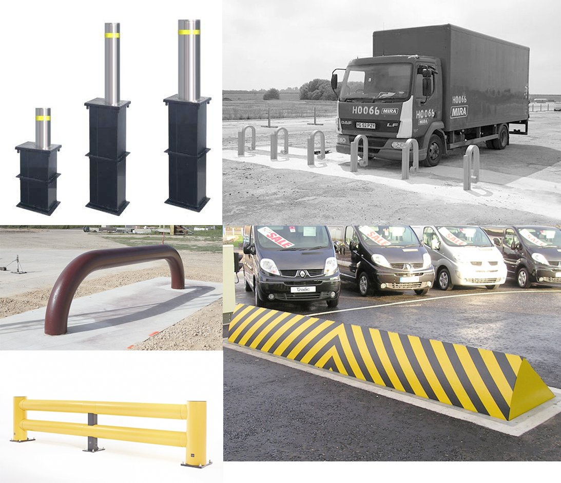 bollards, horns, and ramps.
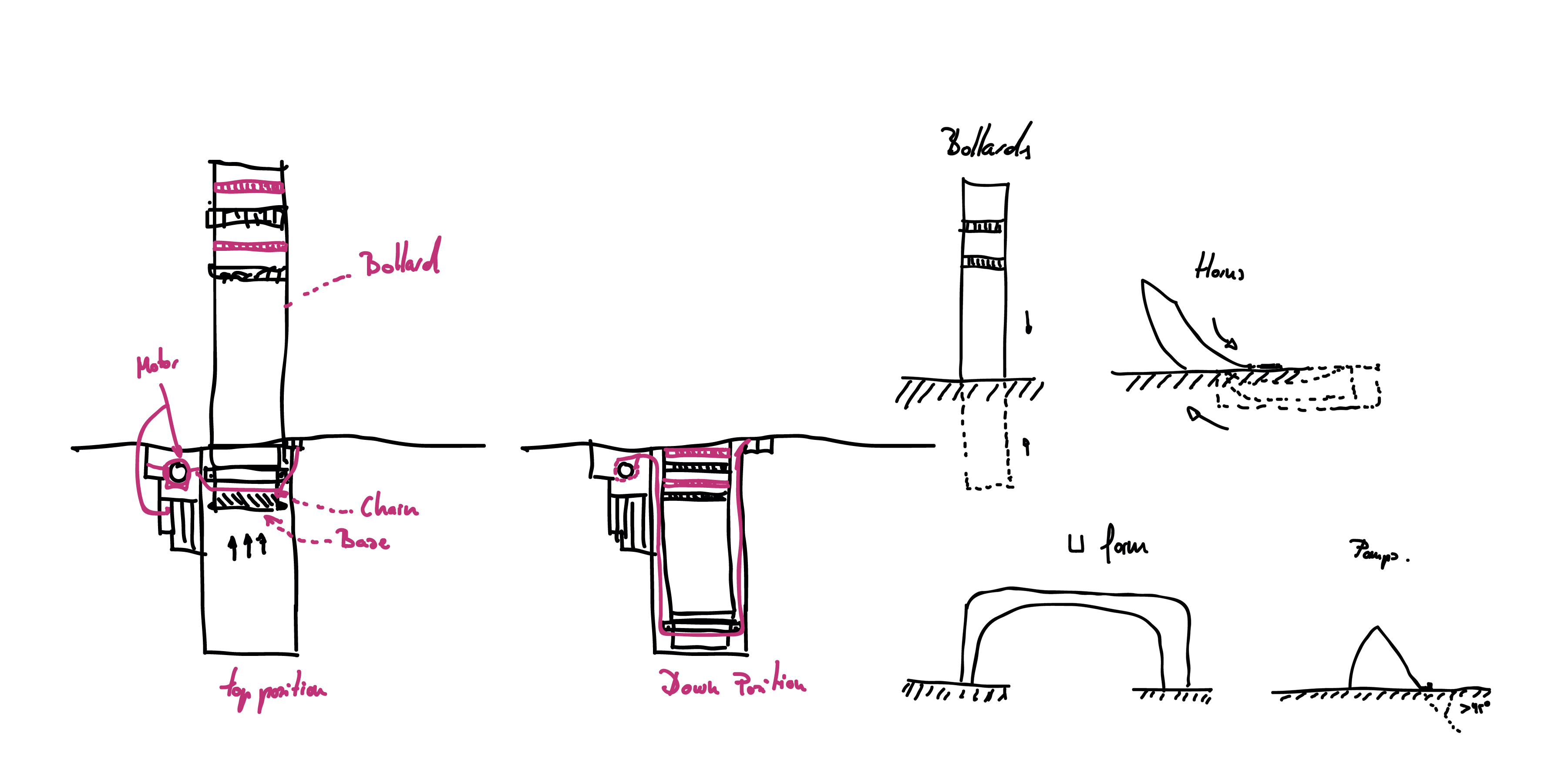
We will choose the ramps, for their greater effectiveness when it comes to heavy vehicles. An example of how one works is shown in this video:
 A recreation of how the barrier works Copyright © 2015 Bremar Automotion. All rights reserved
 The structure and resistance of the ramp Copyright © 2015 Bremar Automotion. All rights reserved
Okay, knowing the type of barrier we want,It is time to design it, the concept is simple a hinge with a spring on its axis, which activates the safety mechanism and the spring causes the ramp to rise.
The main feature of my project remains hidden and unsuspecting camouflaged with the ground, and this is only activated when a real danger is imminent, while the passage of pedestrians or light vehicles like motorcycles or bikes do not activate it.
You do not need a motor to raise it and lower it as it is an emergency safety measure, you can dispense with the engine and put in place a spring mechanism, faster and cheaper.
- An example of a case study -
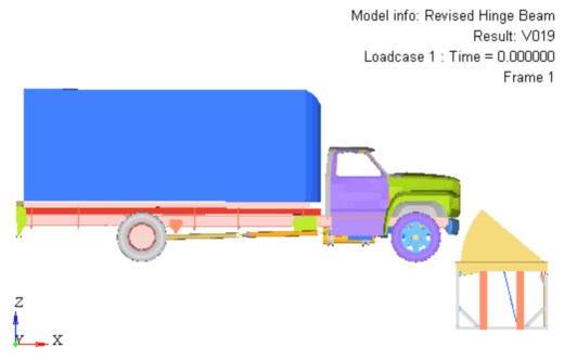
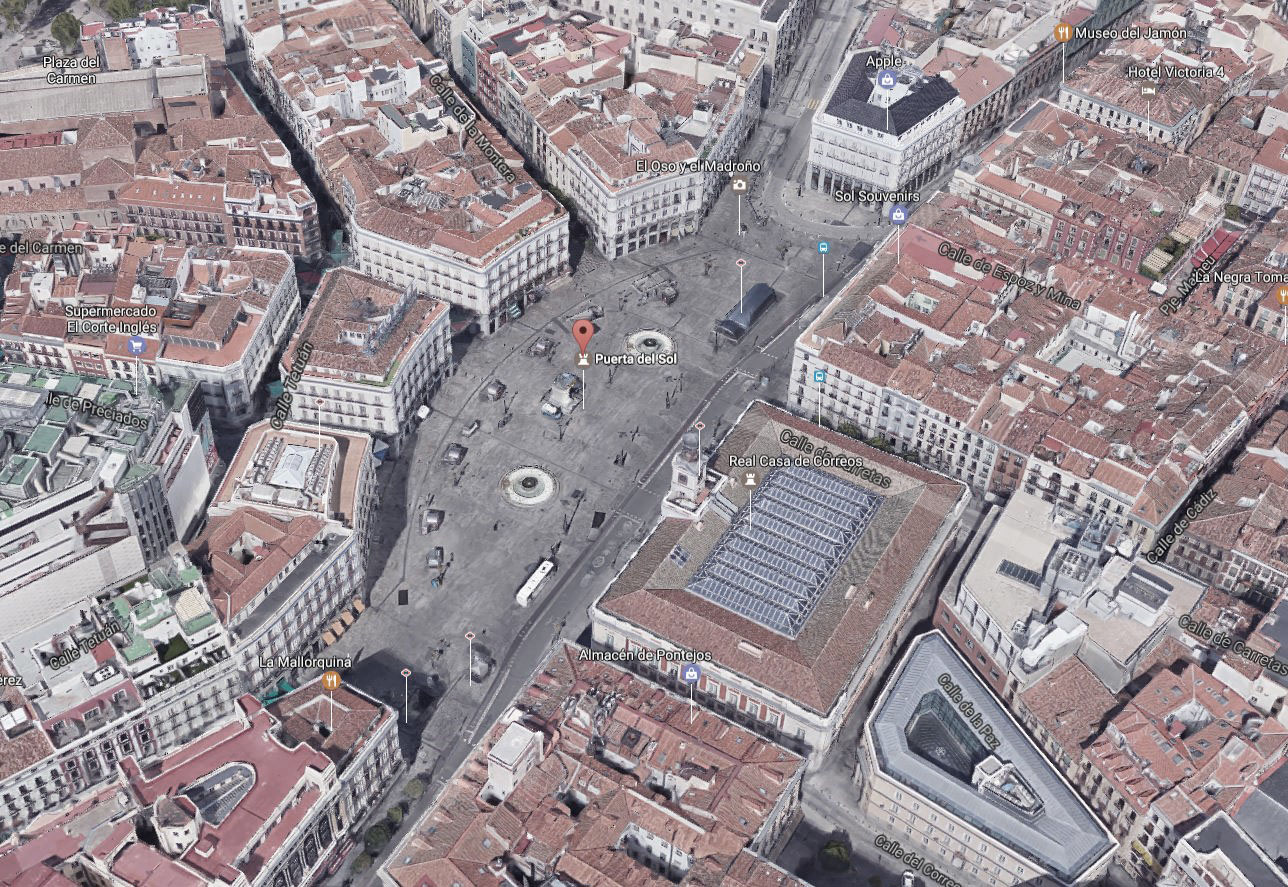
PUERTA DEL SOL, Madrid, With safe square.
And I will simulate the environment of my proposal.The chosen place is Puerta del Sol, the most famous square in Madrid, where events take place and protest march are celebrated.
 Puerta del sol
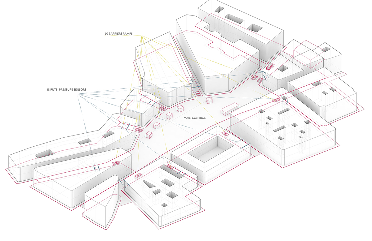
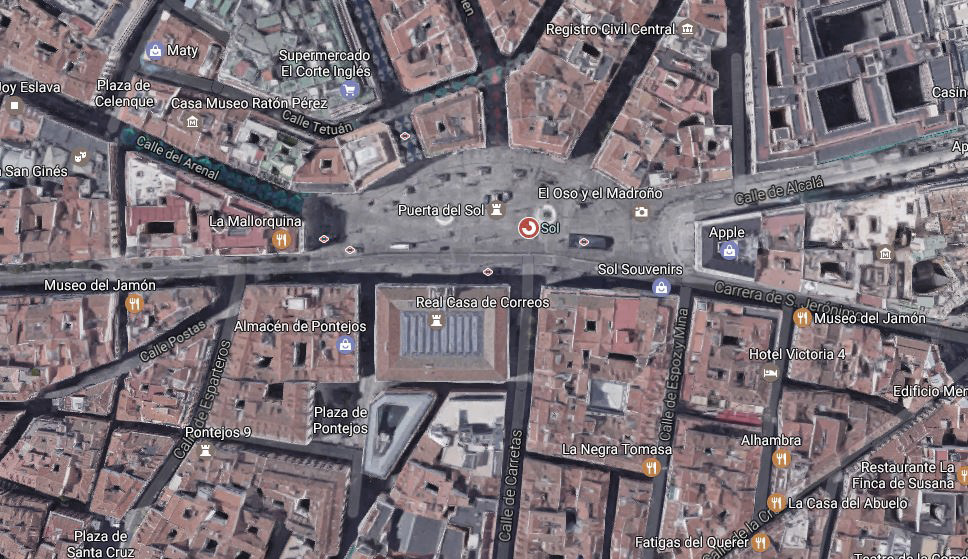 modeling the square.
It has several entrances with semi-pedestrian streets.
I have quickly modeled the scenario,
And I have placed my barriers in the square.
That's how it works.
modeling the square.
It has several entrances with semi-pedestrian streets.
I have quickly modeled the scenario,
And I have placed my barriers in the square.
That's how it works.
 Puerta del sol with safe square.
And so it rises when there is danger near:
Puerta del sol with safe square.
And so it rises when there is danger near:
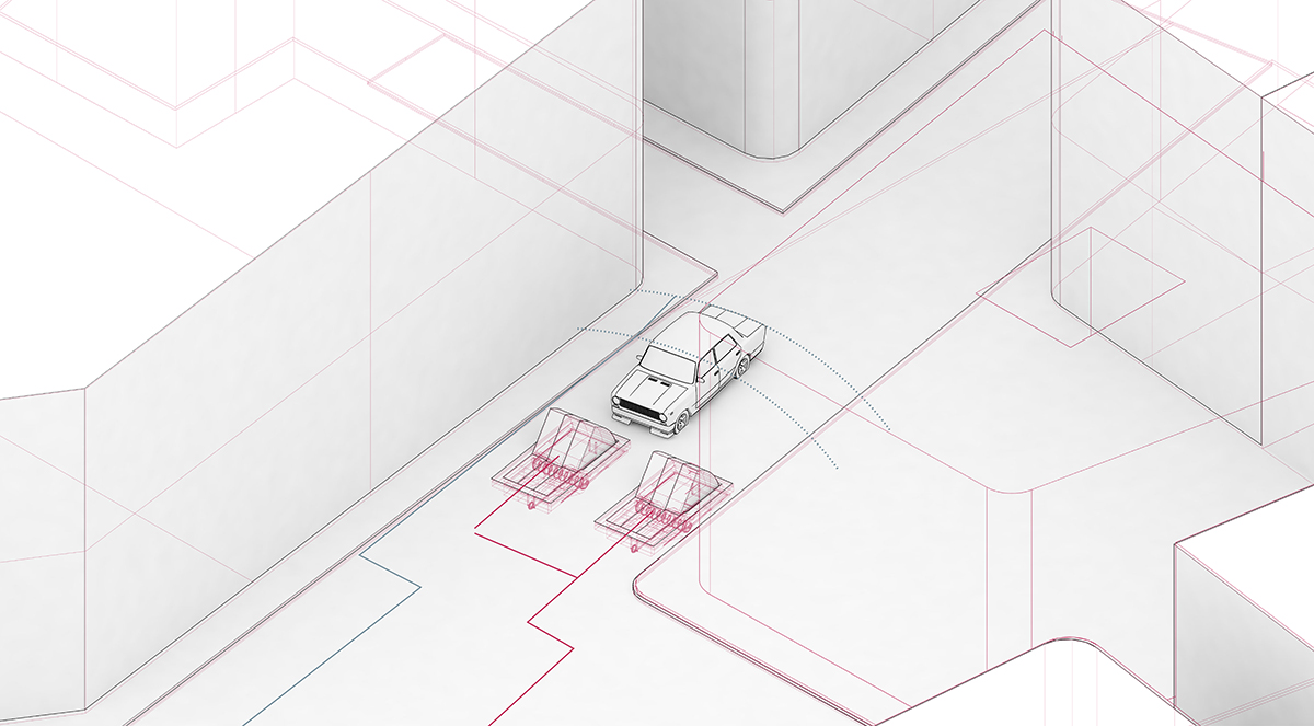 ramps up
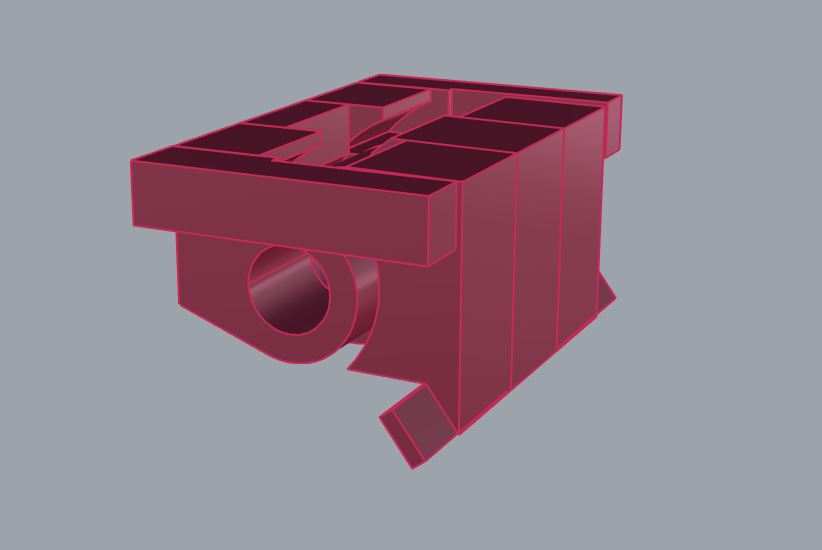
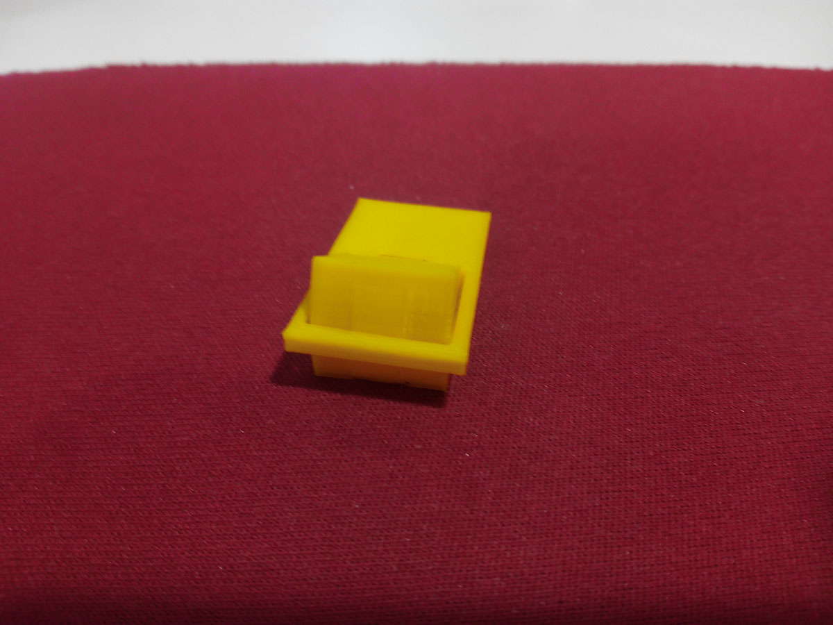 this is a prototype1, Very weak but works as hinge.
As a prototype model it can work, it simplifies well what I want to achieve, it moves mechanically, it remains hidden in the situation of rest, it is solid and it holds.
The next step will be to create a larger prototype with a more advanced mechanical system and a suitable locking system.
Prototyped:
When I advanced a bit in the assignments I decided to make a new prototype, this prototype somewhat more advanced part of the design of a trap for rats.In a first prototyping and obviating accessibility problems, to test the mechanism we made prototype 2, inspired by the spring of the traps for rats
With a scale of 15cm and with different parts, 3d impression of the body, trap spring for rats, and metal fasteners.
Barrier Trap2 by alvarolaroja on Sketchfab
I made the first designs with Rhinoceros improving those that already existed of week 2. This prototype includes a lock system "latch system" a box where to place the body, and the visagra is conformed the own spring of the trap that crosses the body.
 A test for 3d print
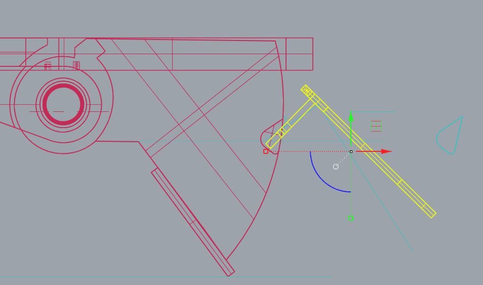 The solution of the motor and spring.
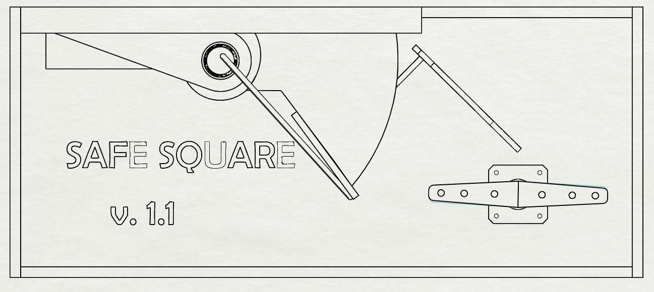 a front-view of the v1.1
I needed a solution to activate the spring in the rest position, at first I thought of this, but it was quite unstable and turned out to be a bad solution, looking for information I noticed the mechanism of the doors and I thought that the lock system could serve me My project.
At home I have locks that do not open and close properly that could serve me to test this system.
Version V1.1 in progress, building and testing:
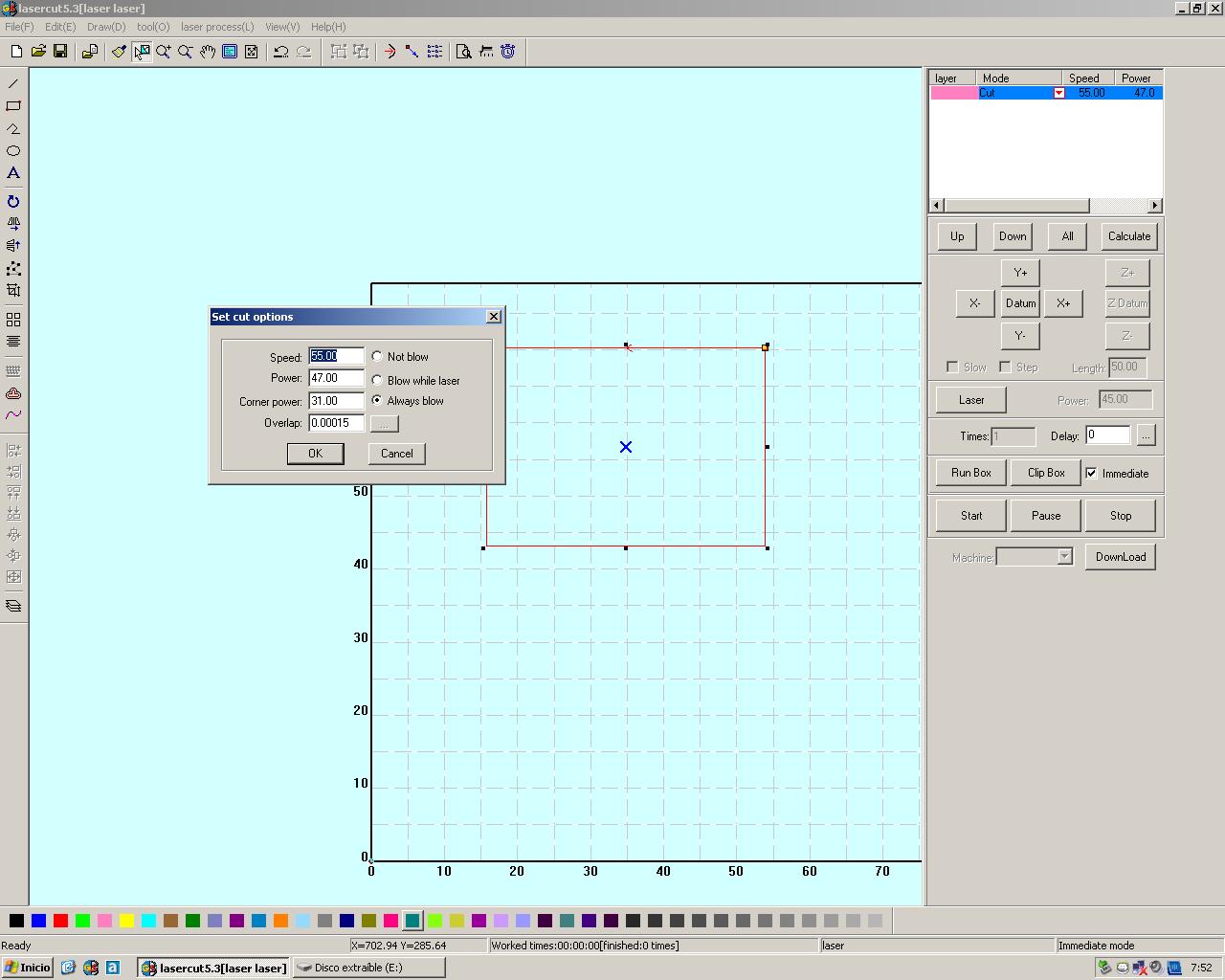
I thought to make this prototype in 3D printing but the amount of time used and the final resistance and the possibility of making limited adjustments. In the end I opted to make the prototype in laser cut, to have the possibility to make adjustments and to change elements, to use glue screws and nuts.
After version 1.1 it is necessary that the elements are more collected. It is also necessary to redesign the latch system so that the ramp is maintained in the 2 positions.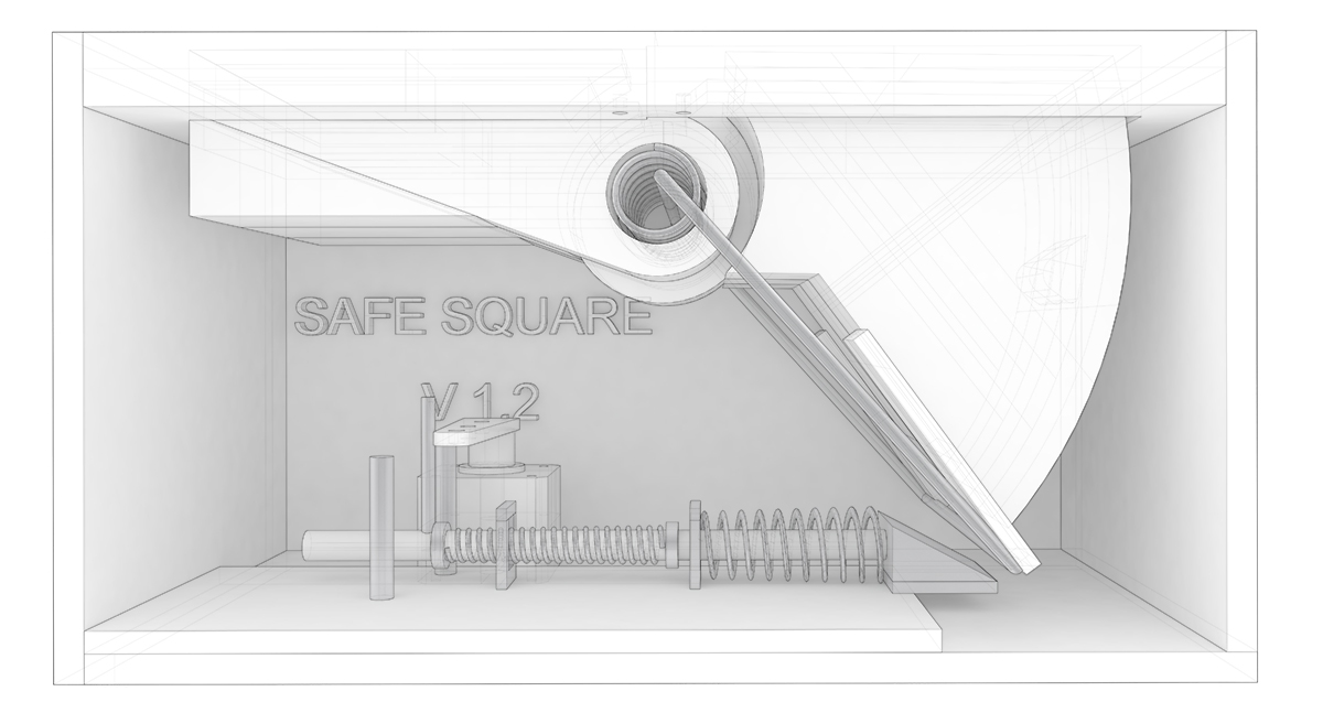
V1.2 of my project (prototype).
I decided to make a quick prototype of the version 1.2 using the laser cutting machine
 For more information on the laser cut assignment click on the following button
And this is how the prototype works mechanically.
More designs:
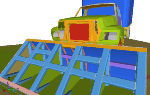
I redesigned the prototype to make it bigger, not at a real scale because I do not have the means or budget for it, however it is on an intermediate scale 1/3 of the real size, with less resistant materials but the purpose is to use the mechanism.
I made a final infographic for the slide, which I include here, along with the final slide.
 final recreation.
Making it real:
I have already verified that the idea can work mechanically, in addition in the assignments of Output and inputs I have advanced enough to have a sketch of the programming and the design of the boards.
The size of the final project is great, and the idea is to contain a summary of all the assignments I have been doing incorporating many of the manufacturing techniques studied.
So I start to make the body to be manufactured in a light and wood CNC machine, the design of this prototype will depend a lot on this type of manufacturing.
For more information on the CNC assignment click on the following button:
Continue to advance with the design, adapting it to the new size and method of fabrication, this one of the final results.
The first thing I will do is the body, the structure and the object box in the cnc machine.
For this I am worth a 3d design that I then went to a cutting plane 2d to mill in the cnc.
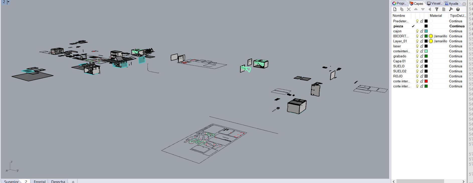
Process of design, many 3D drawings to find the correct sketch.
3D design, in this desing I have tried to maked with less material possible.
Once I have the design reviewed and I know it will work, I export the drawings to 2D to make the cut.
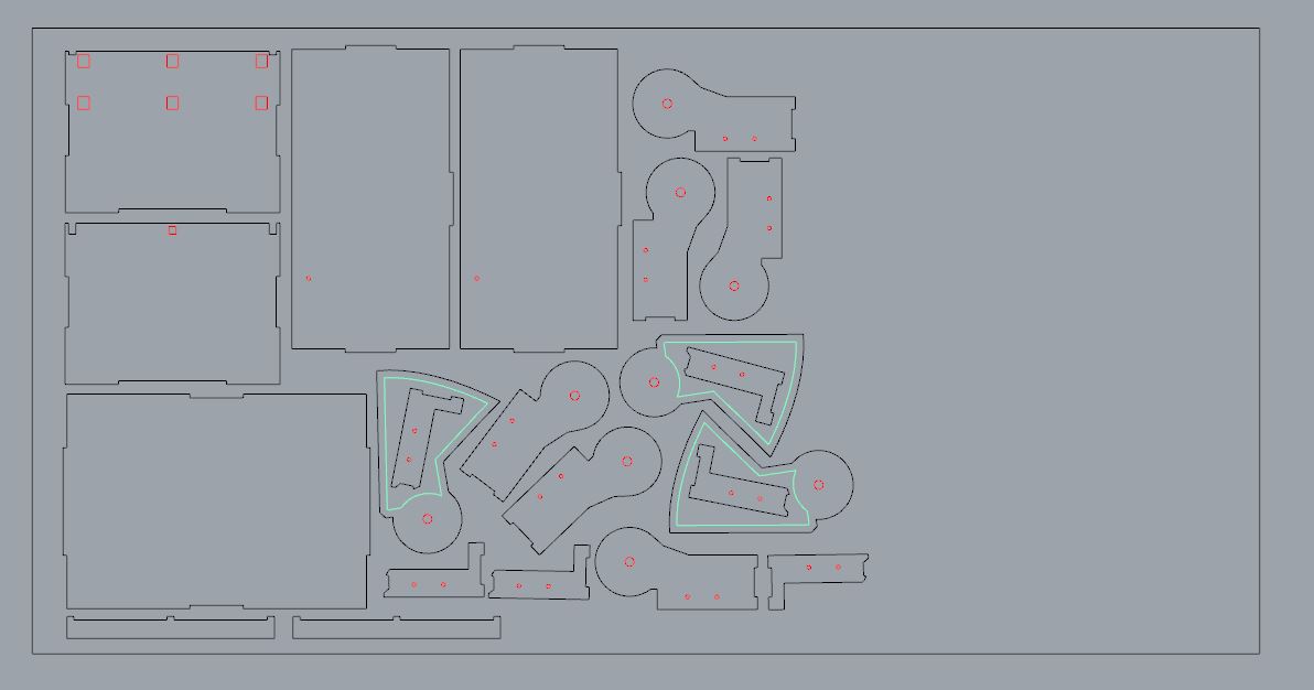
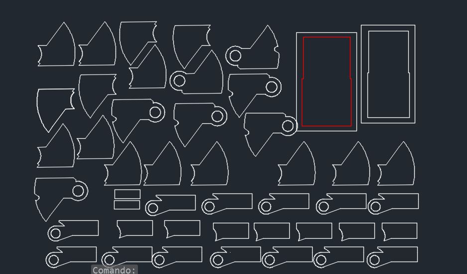
Cutting cnc plan
The cut I made in 4 layers, from the inside out of the piece, always trying to save material by inserting pieces into others if I fit.
I adjusted in each cut what I needed, the size of the material is 7mm MDF wood, for the cut I will use a straight cutter of 2 lips and 6 mm.
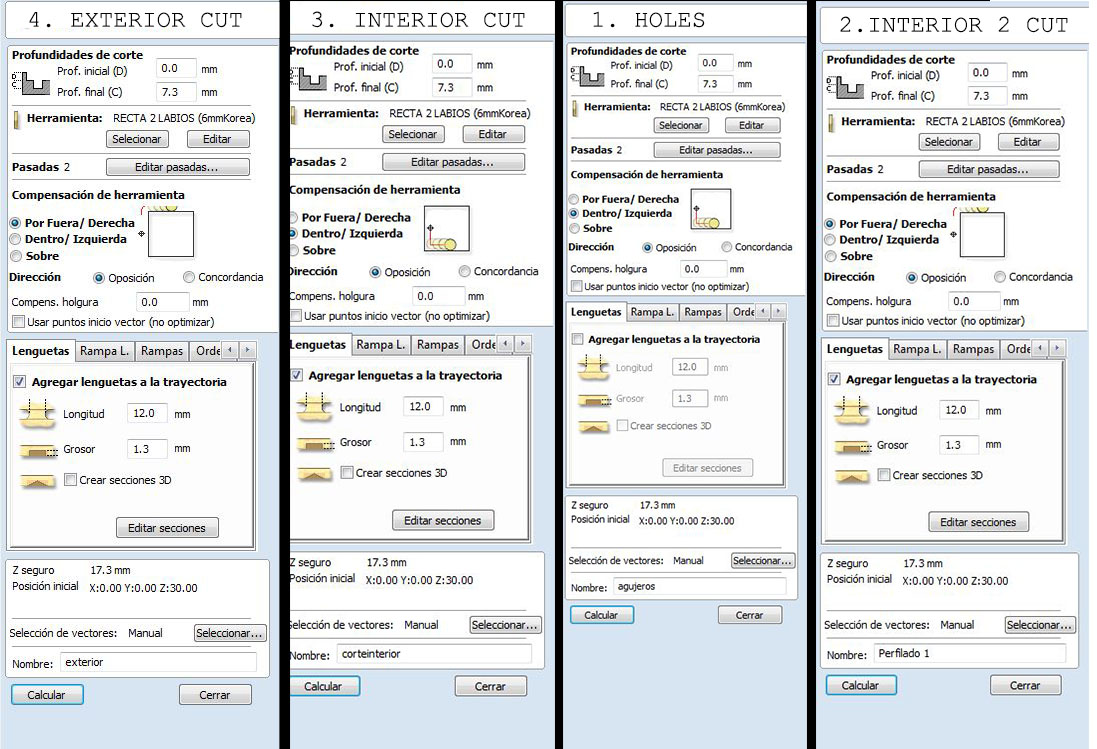
Cutting parameters.
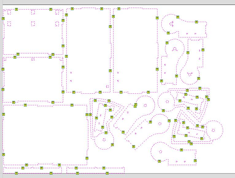
tool paths and tabs.
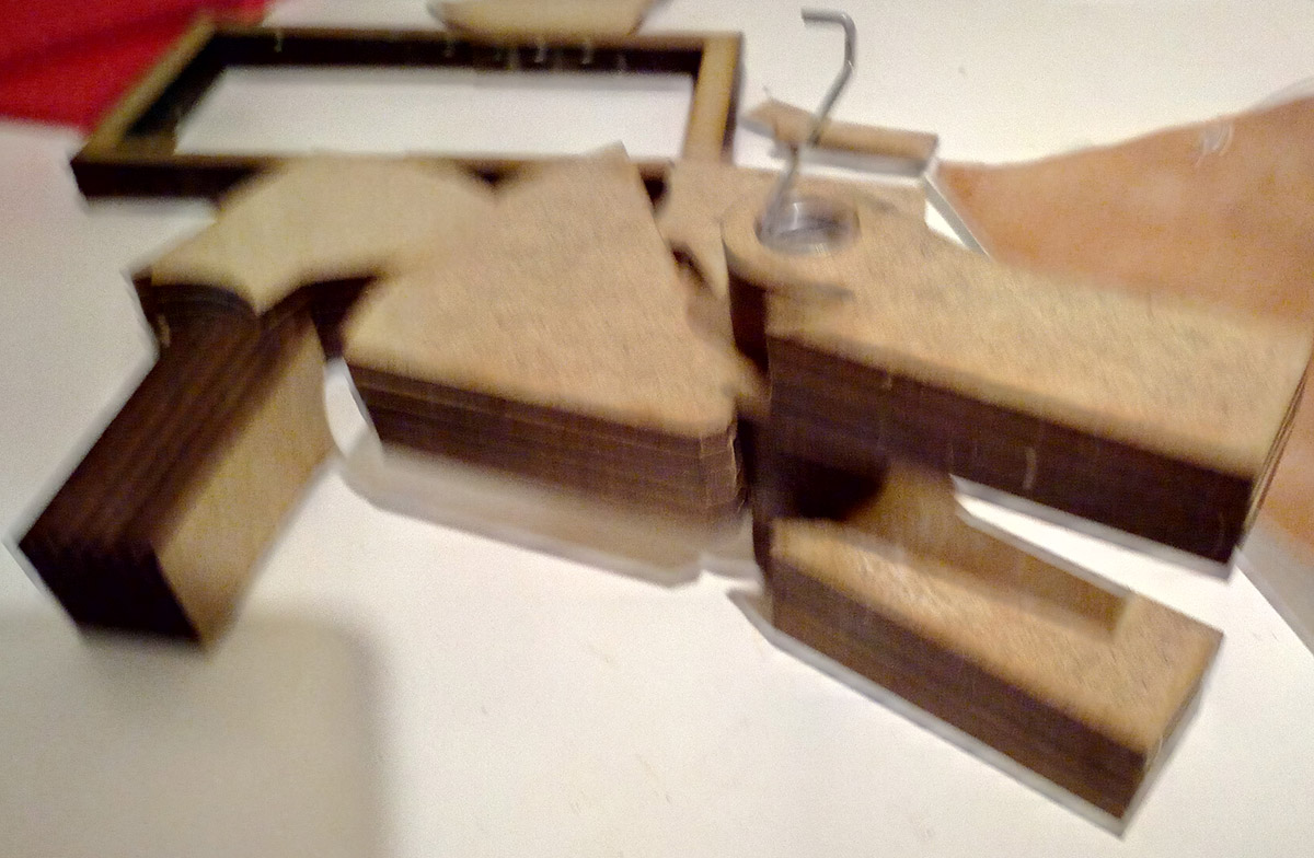
Once the piece is cut I have to carefully peel the tabs I have left so the pieces do not move.
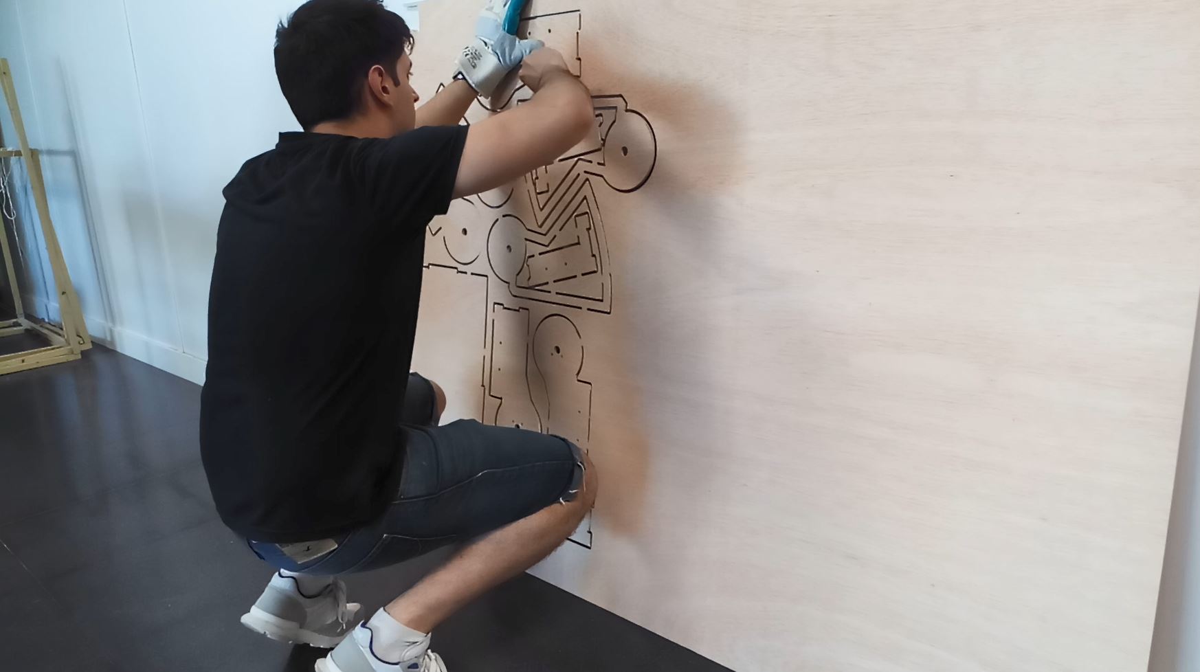
removing the tabs.
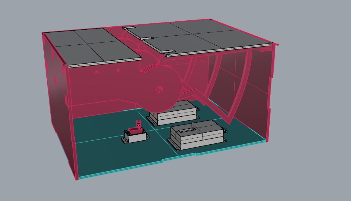
For the transverse rigidity of the body I designed holes to be able to pass rods through the three pieces and keep them rigid.
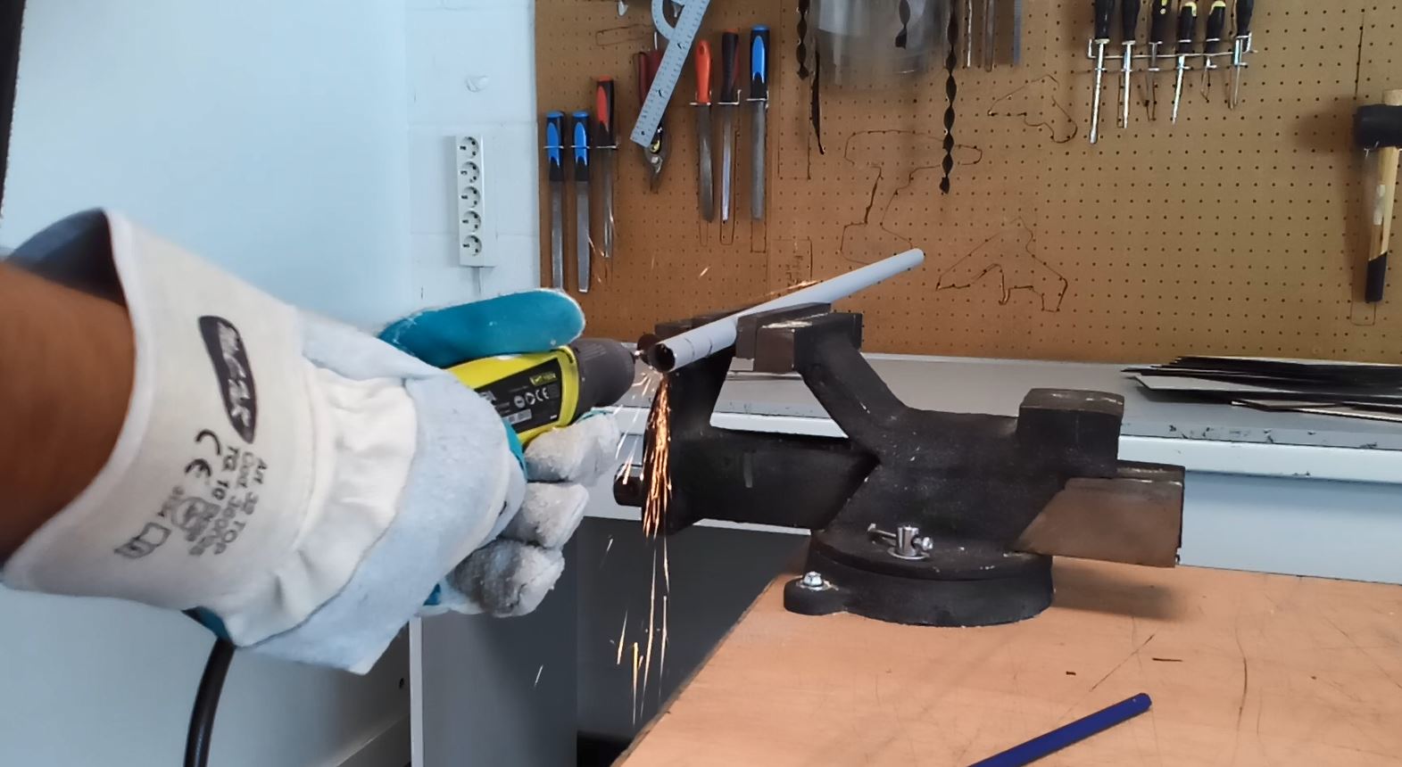
Cutting the cylinders of the springs and the retaining rods.
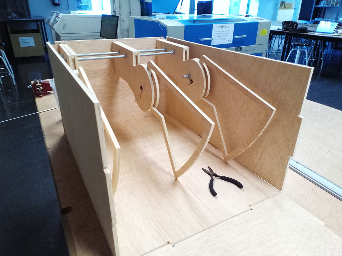
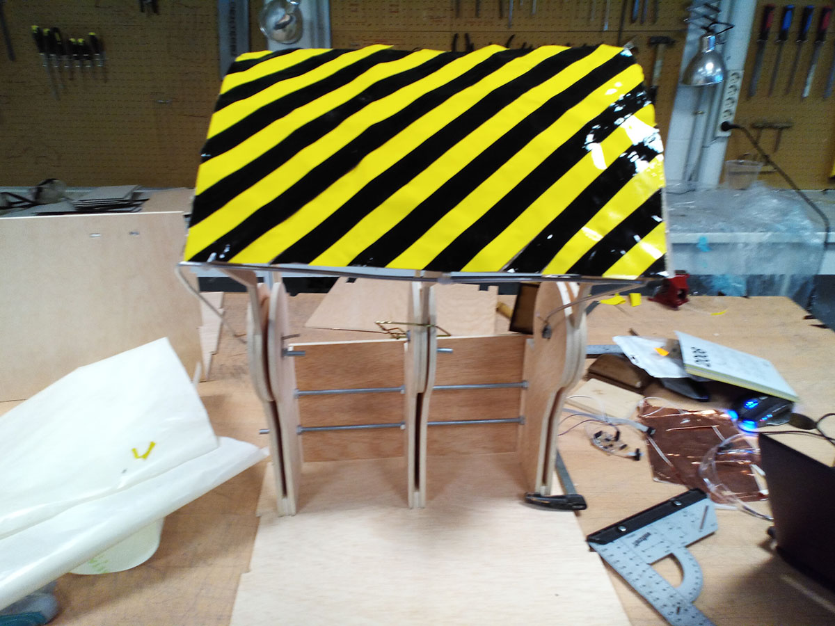
Assembled parts.
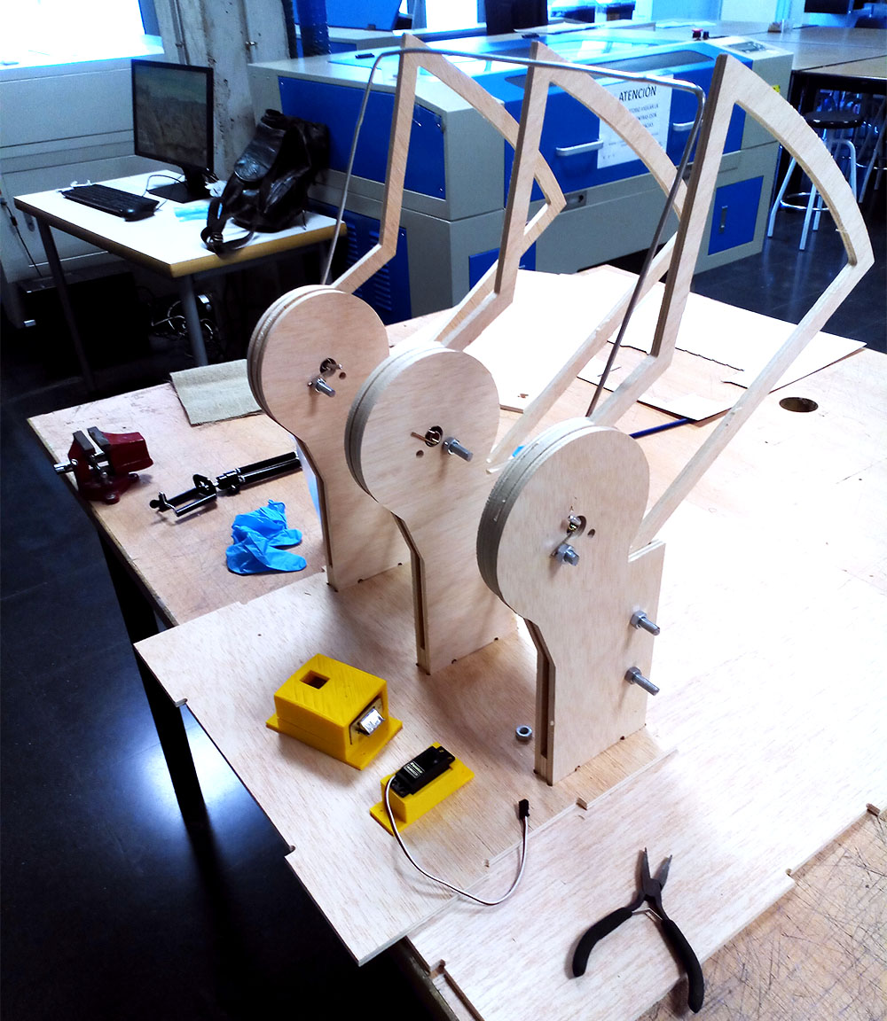
yes! it works.
Once the main body was fitted with the springs, I was able to check that it was mechanically correct, strong enough and strong enough to work.
I placed the transverse rods and a hollow rod where I inserted the spring so that it did not leave the hole.
I used another smaller metal rod that I inserted inside the springs to tighten the ramps.
For more information on the burlap fabric composite assignment click on the following button
The composite is the same that I used for the assignment composites, with a high percentage of resin is a smooth surface, and very hard as we could check in the tests.
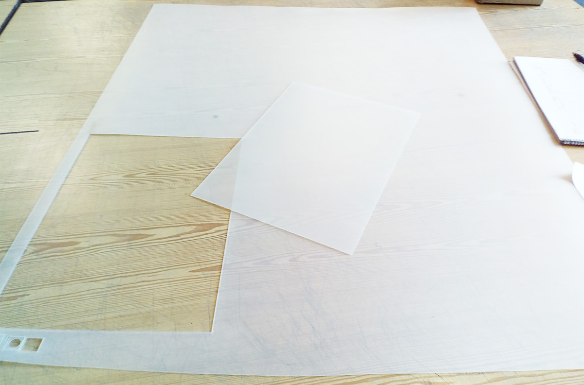
The cut of the composite I will realize it in the laser machine and the size it has taken out of doing a 3d model unfold.
I'm going to make the composite front, this will make my ramp light and resistant at the same time.
I calculate the amounts I have to prepare.
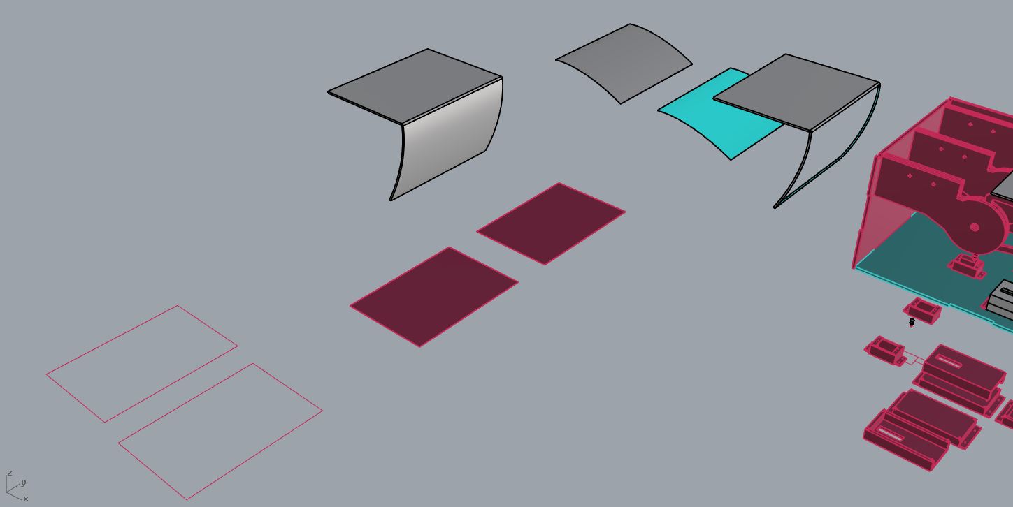
Unfolding the front of the ramp to make the cutting pieces of cloth.
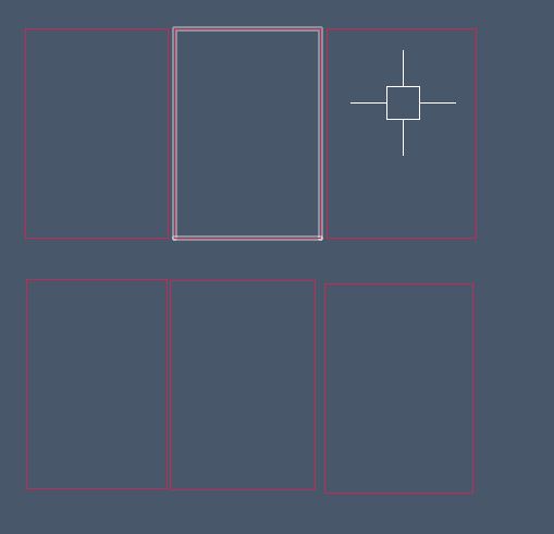
Pieces for cut the cloth, only use 1
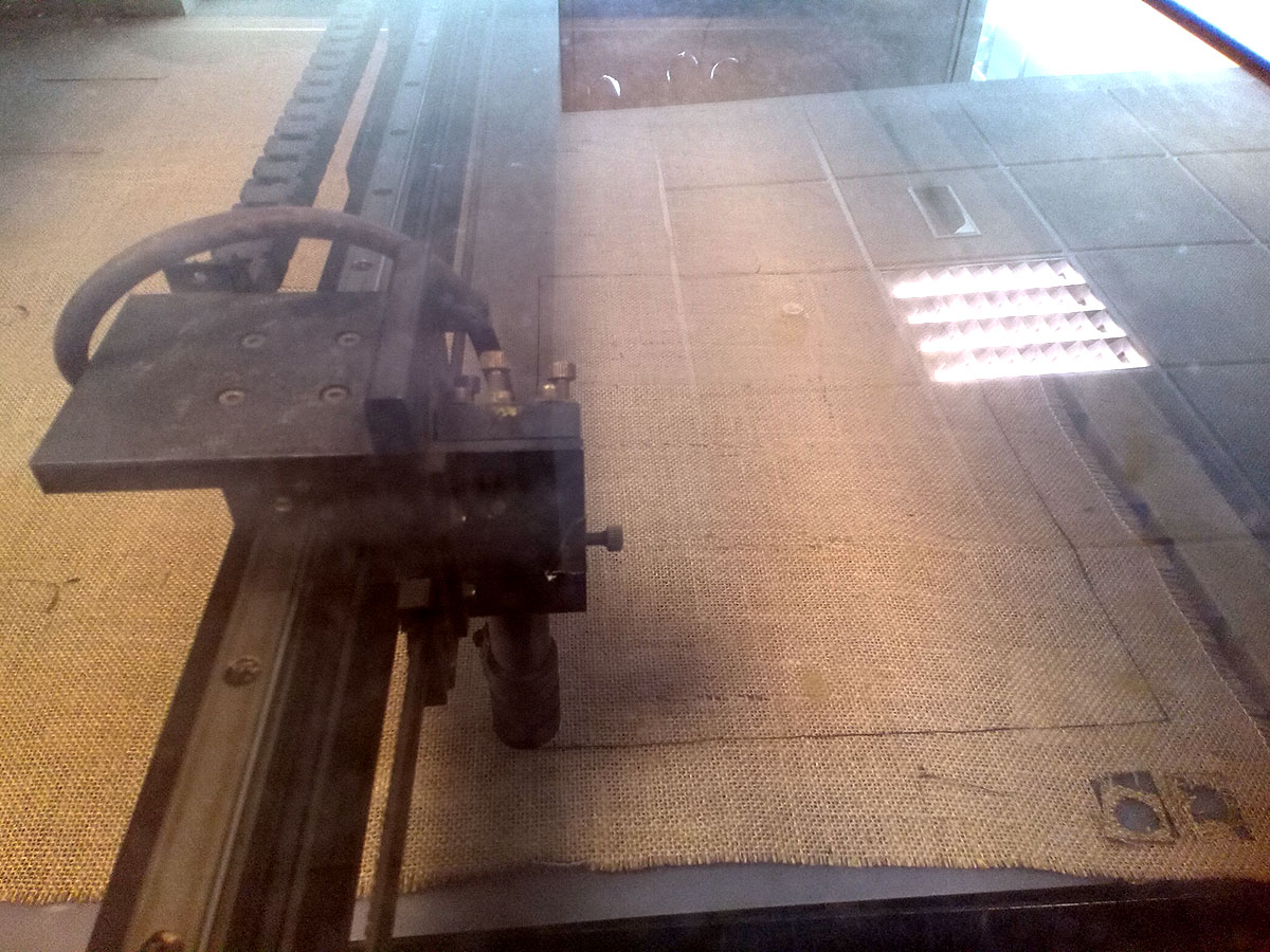
cutting the cloth.
parameters of the cut.
Polypropylene.
I use polypropylene as a rigid composite base, I do the process of mixing the resin with the protective measures and I spread it over the fabric.
With the resin-soaked fabric I place it on the surface that will be the ramp.
For it to dry properly and as it did not matter that the shape of the composite was perfect and putting pressure could cause it to slip and decouple the composite.
I chose to wrap the composite to the structure with fill paper and leave it with adhesive tape so that it remained in its position until it dried.
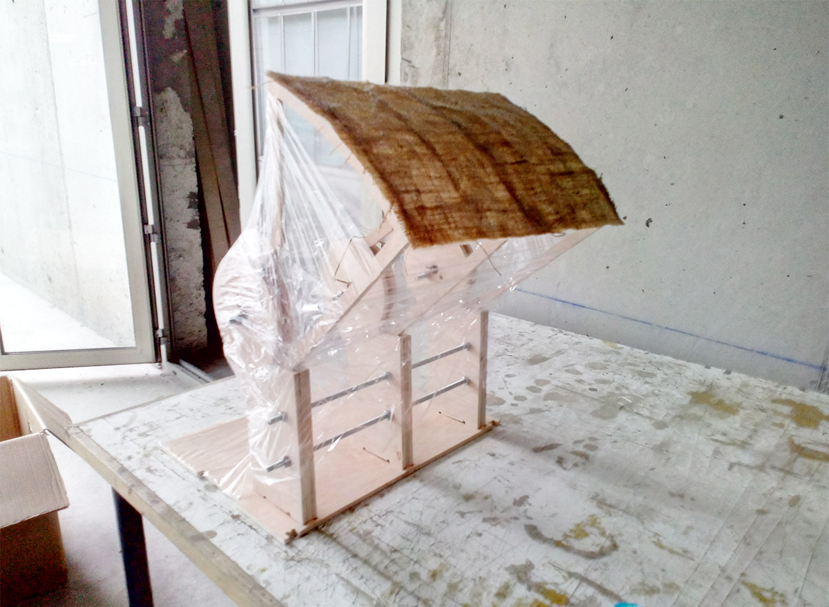
Drying the composite.
For more information on the vinyl cut assignment click on the following button
I will use the vinyl machine to sign the ramp when it is up.
I made the pattern from the 3d model to know the exact measurements, and with a vectorized diagonal line.
the exterior surface its unfolded to cut the vynil.
cutting yelow and black vynil.
To create the file it was very easy, I exported the drawing from rhino to dxf and then I opened it in illustrator, the file I opened had the measurements I drew, I copied a photo of the internet looking for "diagonal lines" and then I did a image caption vectorize that image, I exported it and cut it in the roland.
Vynil patterns.
cutting yelow and black vynil.
These are the images of the cut file for black and yellow, actually with one of them is worth since the cut that makes the machine for this pattern no matter what is the positive or the negative, then once cut open that to decide which lines are the ones that I stay and which I suppress.
vynil finish
Electronic parts:
The following diagram shows the electronic operation:
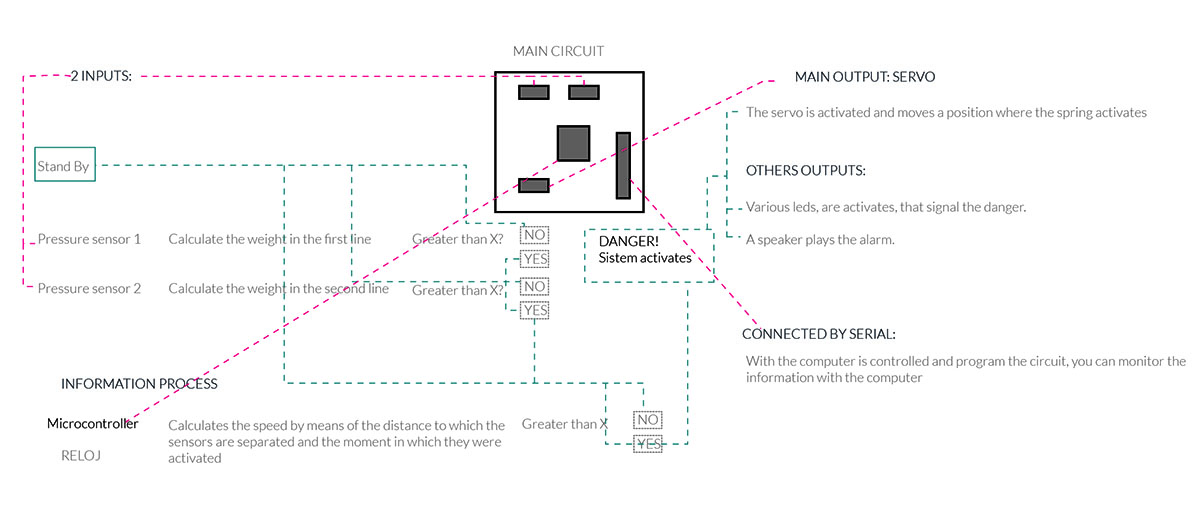 I will need an Output and an input for my final project, I also designed in networking a board to control it without PC.
For more information on the programming assignment click on the following button:
OUTPUT of final project:
For more information on the Input-Output-Networking assignment click on the following button:
The output of the final project consists of a board with the atmega 168 microcontroller and the necessary components to:
1. Connect the Futaba S3000 servomotor.
2. Connect serially to the PC via FTDI and using cables to the Input.
3. Bootloader can be done using a Fab ISP.
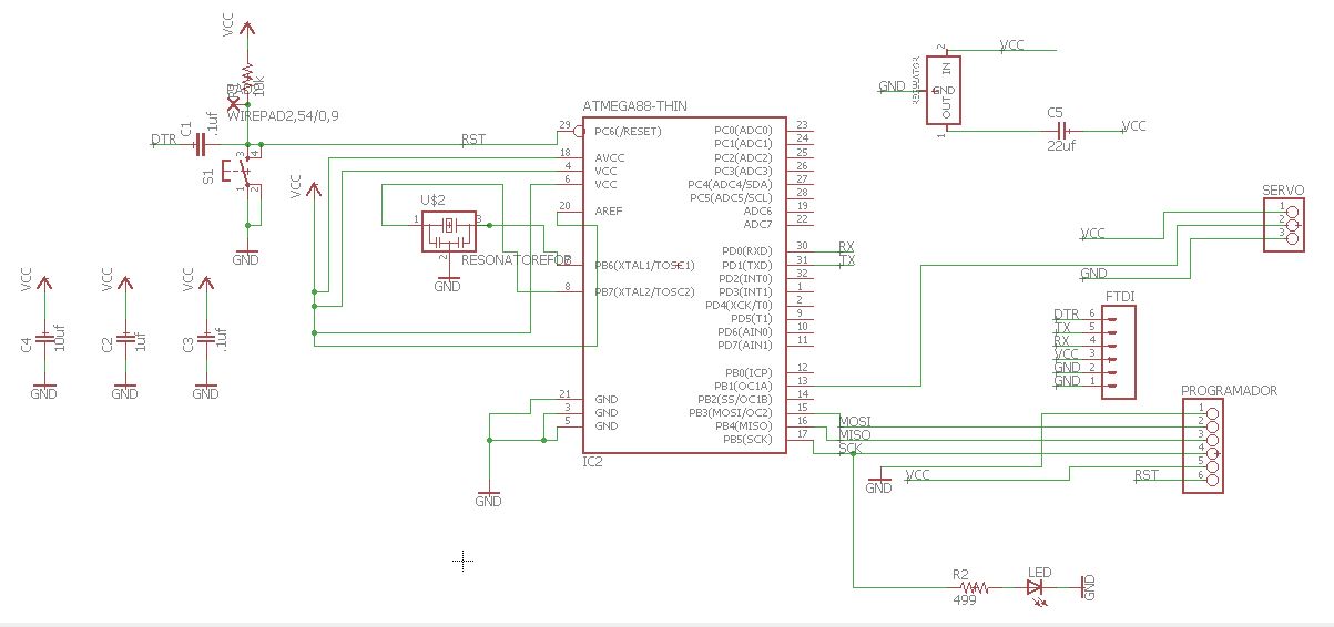
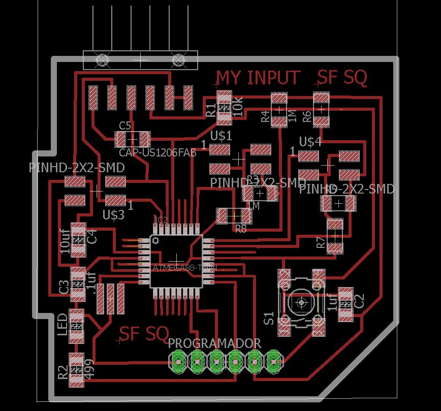
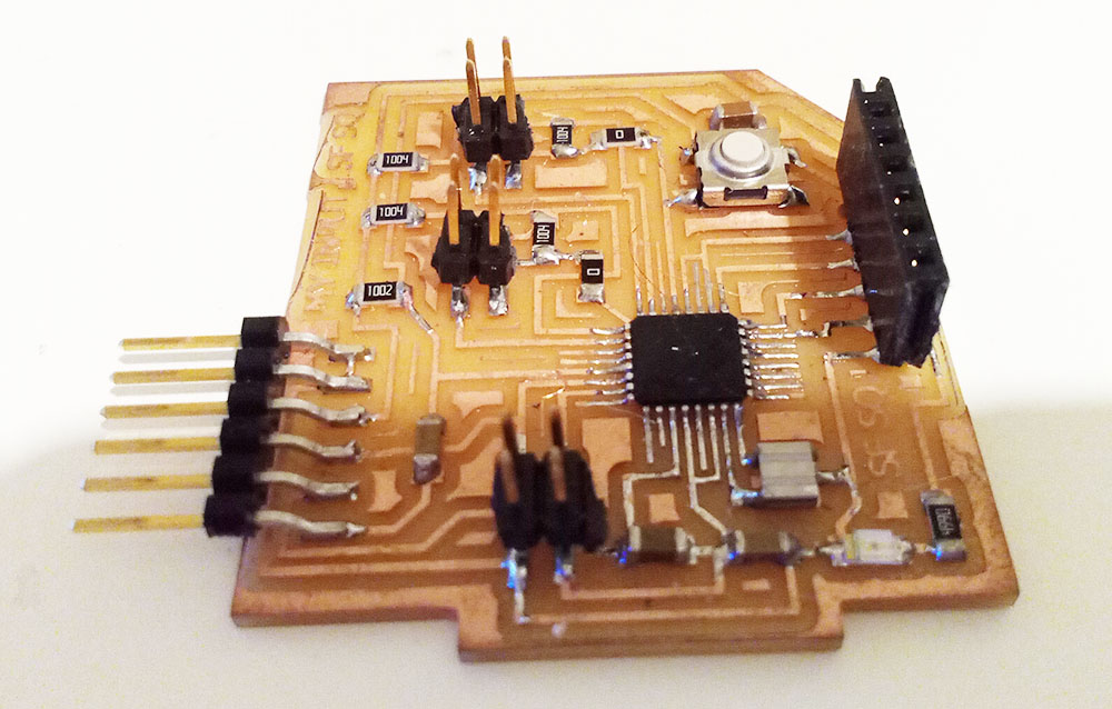
Final schematic
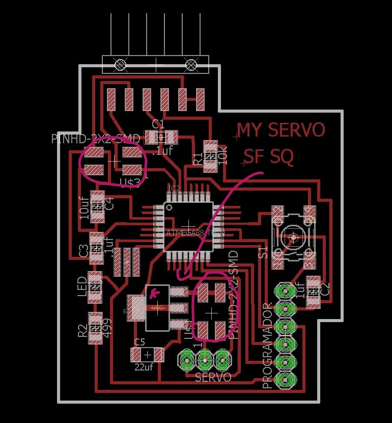
Design boards and the diference with other boardsmade it before.
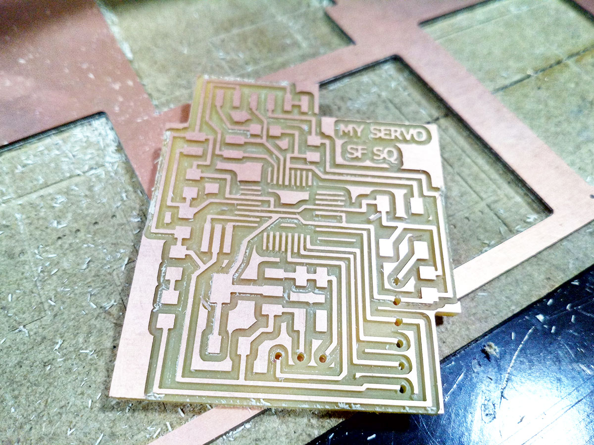
my board
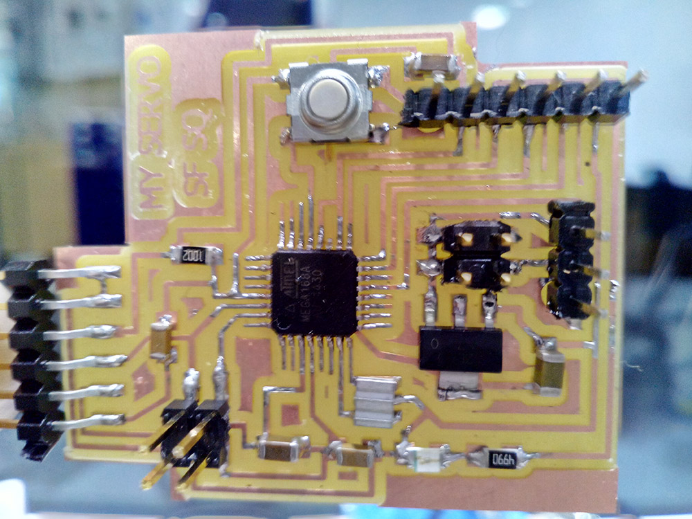
the board with components soldered.
Output program:
As a program made by me from 0, for the output is the one I will use for my final project, what I want is that when I receive a signal for the serial monitor of 5, a certain angle is moved and when I receive an 8 return to the initial position.
#include <SoftwareSerial.h>

#include <Servo.h>


Servo finalservo;

int pos = 10;
int act = 160;
int encendido=0;
void setup(){
Serial.begin(9600);

  myservo.attach(9);
}

void loop() {


  if (Serial.available()) {
    encendido = Serial.read();
    /*if (encendido == '5') {

        // servo en posicion pos
       myservo.write(pos);


      }
      */
      // Si es una 'L'
      if (encendido == '8'){

        myservo.write(pos);              // tell servo to go to position in variable 'pos'
                          // waits 15ms for the servo to reach the position*/

      delay(1000);
      }

            myservo.write(act);

 /*// for (pos = 0; pos <= 180; pos += 1)

    myservo.write(pos);
    delay(4000);
 // for (pos = 180; pos >= 0; pos -= 1)
    myservo.write(act);
    delay(1000);
  }
 }
INPUT of final project:For more information on the Input/Networking assignment click on the following button:
The input of my project will have as microcontroller an Atmega 168 and the necessary components to:
1. 2 outputs with pin header for sensors connected to digital analog pins.
2. Connect serially to the PC via FTDI and using cables to the Input.
3. Bootloader can be done using a Fab ISP.
Although in the end I only used one the idea was to have 2 pressure sensors that in addition to the pressure could by calculations in the programming calculate the speed at which the object goes.
I add another space for the sensor, which has to be connected to the nearby pins, the function of having 2 sensors of these could be calculate in addition to a large weight calculate the speed between two sensors separated a distance.
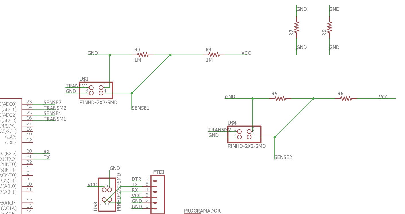
Schematic
On the other side I also add the pin for serial communication.
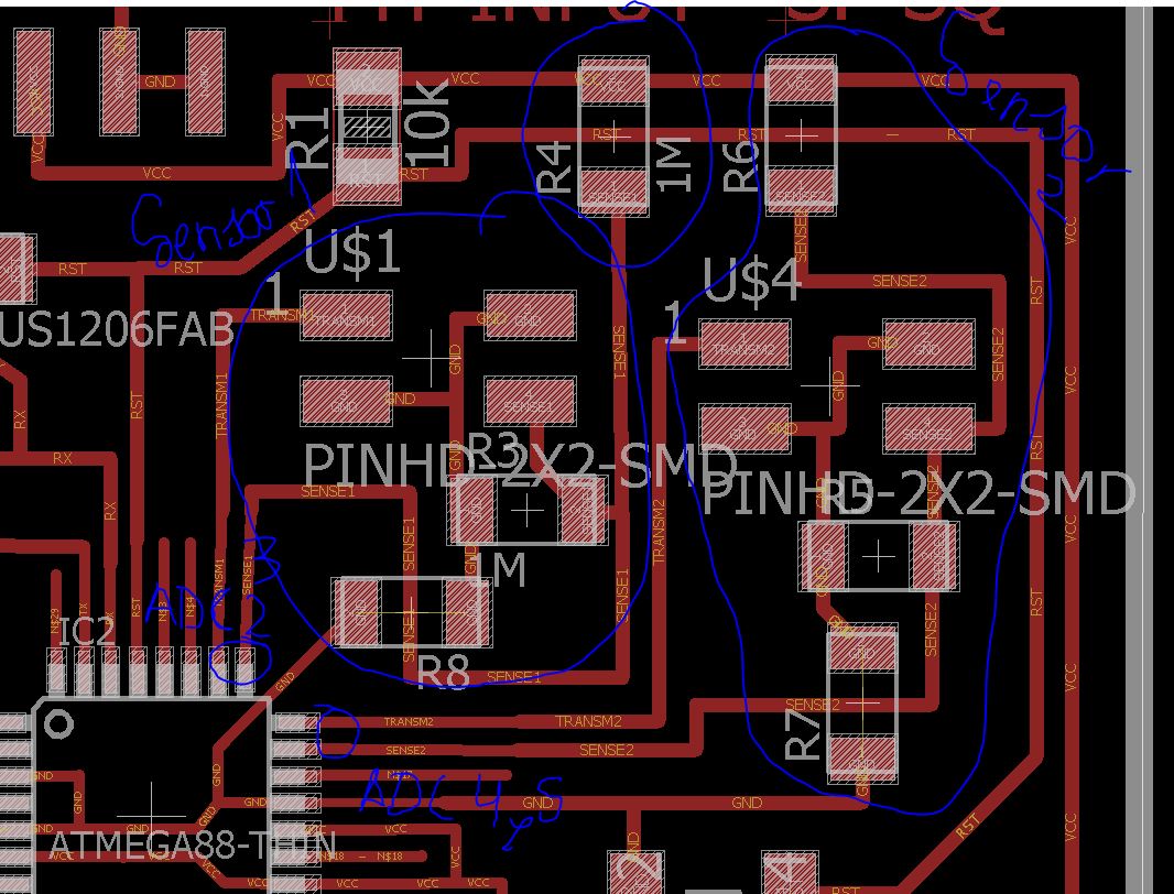
New sensors
Final Input board
You can see how to mill the board in week 13.
this is the final result, the plate with the connectors to which the pressure sensor will be connected.
The 3 boards for mi final project, fabricated, tested, and programmed.
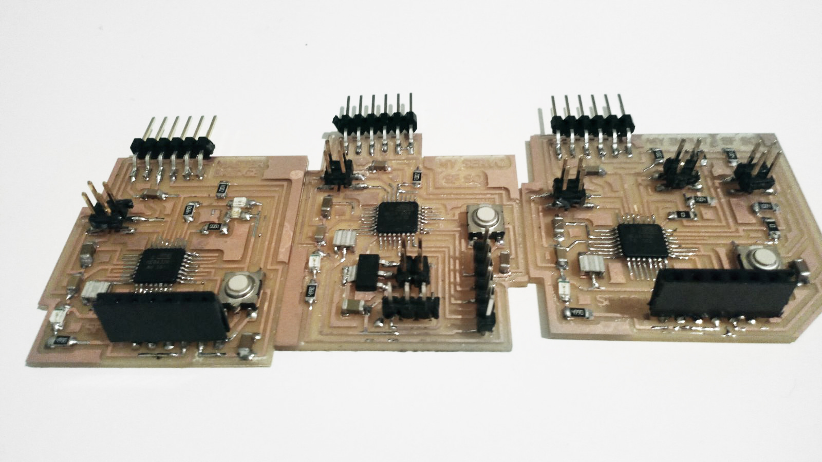
3 Boards, Networking, Servo and Input.
And there is the programming of the board, which will send information to the servo so that it is activated or is kept in the rest position.
/* Programmed by Alvarolaroja 23/05/2017 traduced from Neil G. in C Hello TxRx */

#include <avr/io.h>
#include <util/delay.h>


static uint16_t up,down;
static uint16_t arriba, abajo;

void setup() {
  // pinMode(A3, OUTPUT);
  DDRC |= (1 << PC3);
  PORTC &= (~(1 << PC3));
  Serial.begin(9600);

  ADMUX =  (0 << REFS1) | (0 << REFS0) | (0 << ADLAR) | (0 << MUX3) | (0 << MUX2) | (1 << MUX1) | (0 << MUX0);//PC2 input
  ADCSRA = (1 << ADEN) | (1 << ADPS2) | (1 << ADPS1) | (1 << ADPS0);//prescaler 128
}

void loop() {
      up = 0;
      down = 0;
      for (int count = 0; count < 100; ++count) {
        _delay_us(100);
        PORTC |= (1 << PC3);
        //digitalWrite(A3,1);
        //arriba = analogRead(A2);
        ADCSRA |= (1 << ADSC);
        while (ADCSRA & (1 << ADSC)){
            ;}
        //up += arriba;
        up += ADC;
        //mySerial.println(up);

        _delay_us(100);
        PORTC &= (~(1 << PC3));
        //digitalWrite(A3,0);
        //abajo = analogRead(A2);
        ADCSRA |= (1 << ADSC);
        while (ADCSRA & (1 << ADSC)){
            ;}
        down += ADC;
        //down += abajo;
         }


    if ((up-down)<47000)
    {


    {
      Serial.println(up-down);
      Serial.println('5');
      _delay_ms(10);

      // Enviamos 'L' por el puerto serie (TX)

    }
     else
    {

 Serial.println(up-down);
Serial.println('8');

delay(500);
    }


         }


         }
   /*
      Serial.write(1);
      _delay_ms(10);
      Serial.write(2);
      _delay_ms(10);
      Serial.write(3);
      _delay_ms(10);
      Serial.write(4);

      Serial.write((up & 255));
      _delay_ms(10);
      Serial.write(((up >> 8) & 255));
      _delay_ms(10);
      Serial.write((down & 255));
      _delay_ms(10);
      Serial.write(((down >> 8) & 255));
      _delay_ms(10);*/
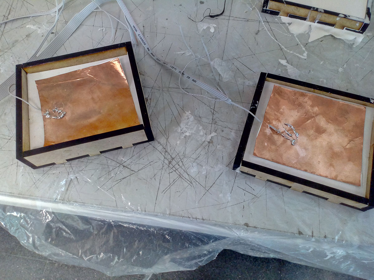
I will fabricate a sensor with two copper plates and an element in between so that the voltage difference will vary when they are closer together and when they are more apart.
In this way what I put between the copper plates to be elastic will make my sensor more sensitive or less depending on what deformed the material and other factors such as conductivity.
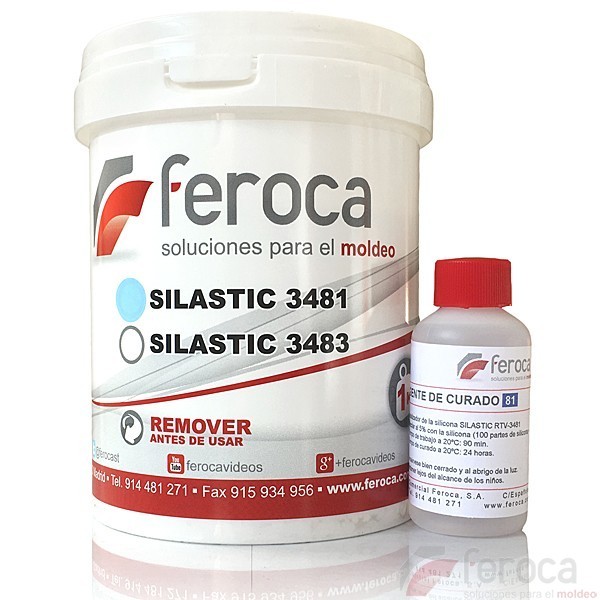
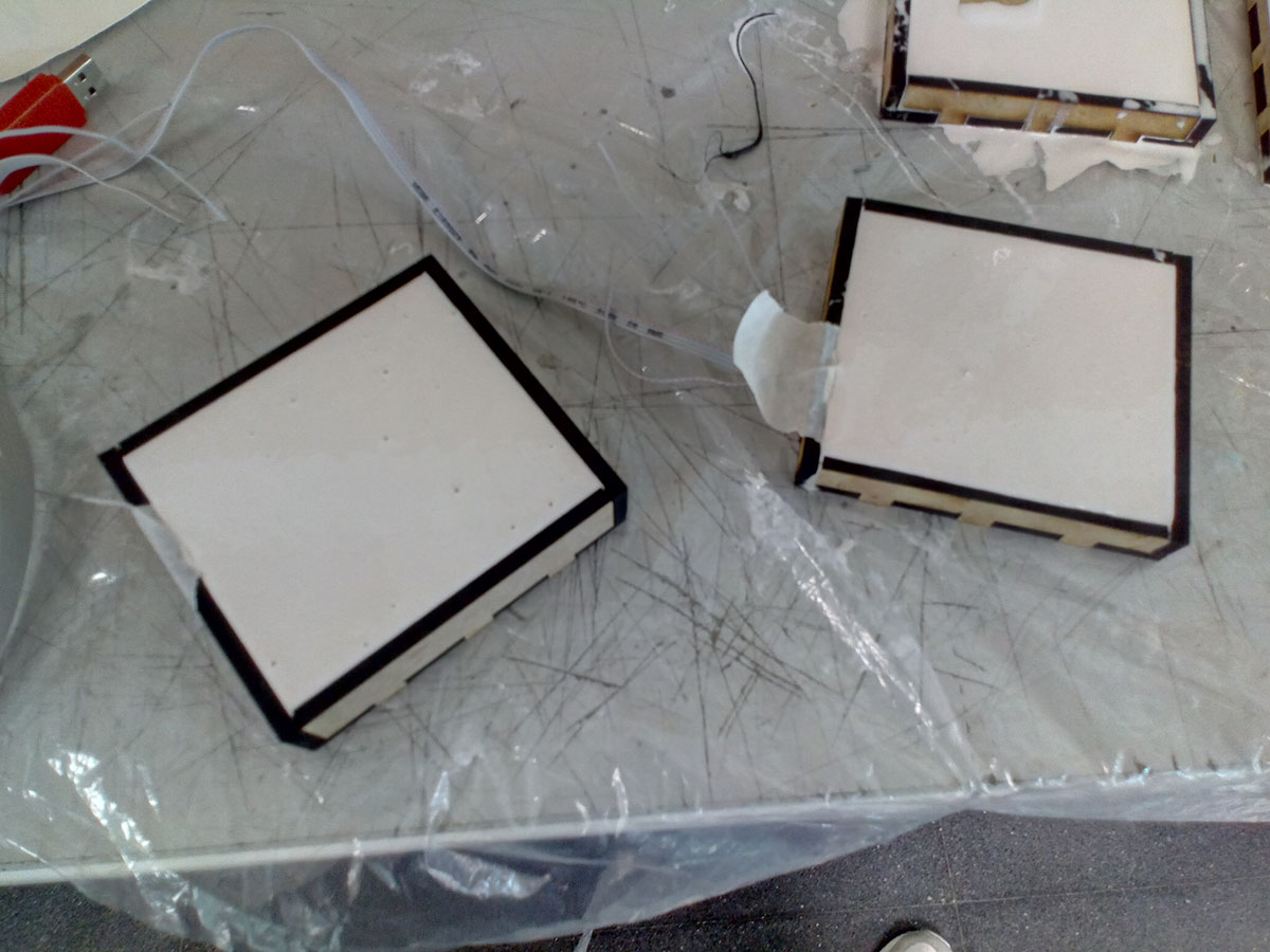
To make the rubber of the sensor, I will make some molds that are boxes, 5mm 10mm and 20mm high.
To pour the silastic 3481 and get rubber sheets.
Rubber used in the sensor covering.
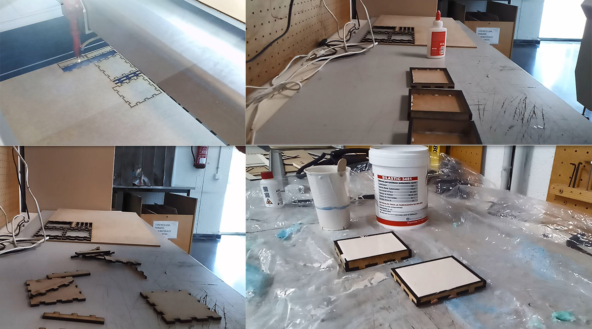
cutting,glue and making boxes and the rubber .
the sensor works as follows, being a potential difference by programming the current that reaches the pins of the microcontroller to which the sensors are connected, if the difference in voltage between the two is very large the result of the programming will be a large number, if the two plates are close together the voltage differential will be small and will tend to 0.
The pressure that is exerted will vary the number that is read in the serial monitor in the programming.
We have on the one hand the receiver and on the other the transmitter, we will place the RX and TX in the way Neil explains in the example helloTxRx.
You can see how Neil explains the helloTxRx and how to make a capacitive pressure sensor in the next video.
In this video how to place the sensor, what other possibilities can be made with this type of sensors and how the dielectrics sensors work. MIN 51:00
I have made two sensors to be able to calibrate better, one of the sensors will have less quantity than another and will be by test when you see which is better and more resistant to do the final project.
The tx goes to the copper plate while the rx returns from the vcc divider and the Gnd and returns to the pin.
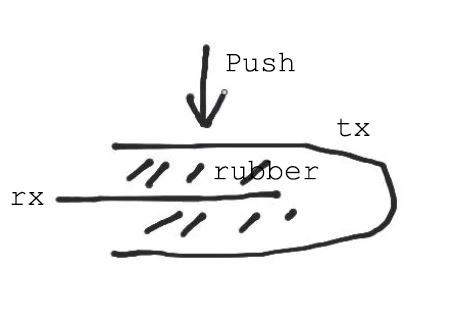
The receiver is placed inside the rubber and the transmitter around it wrapping.
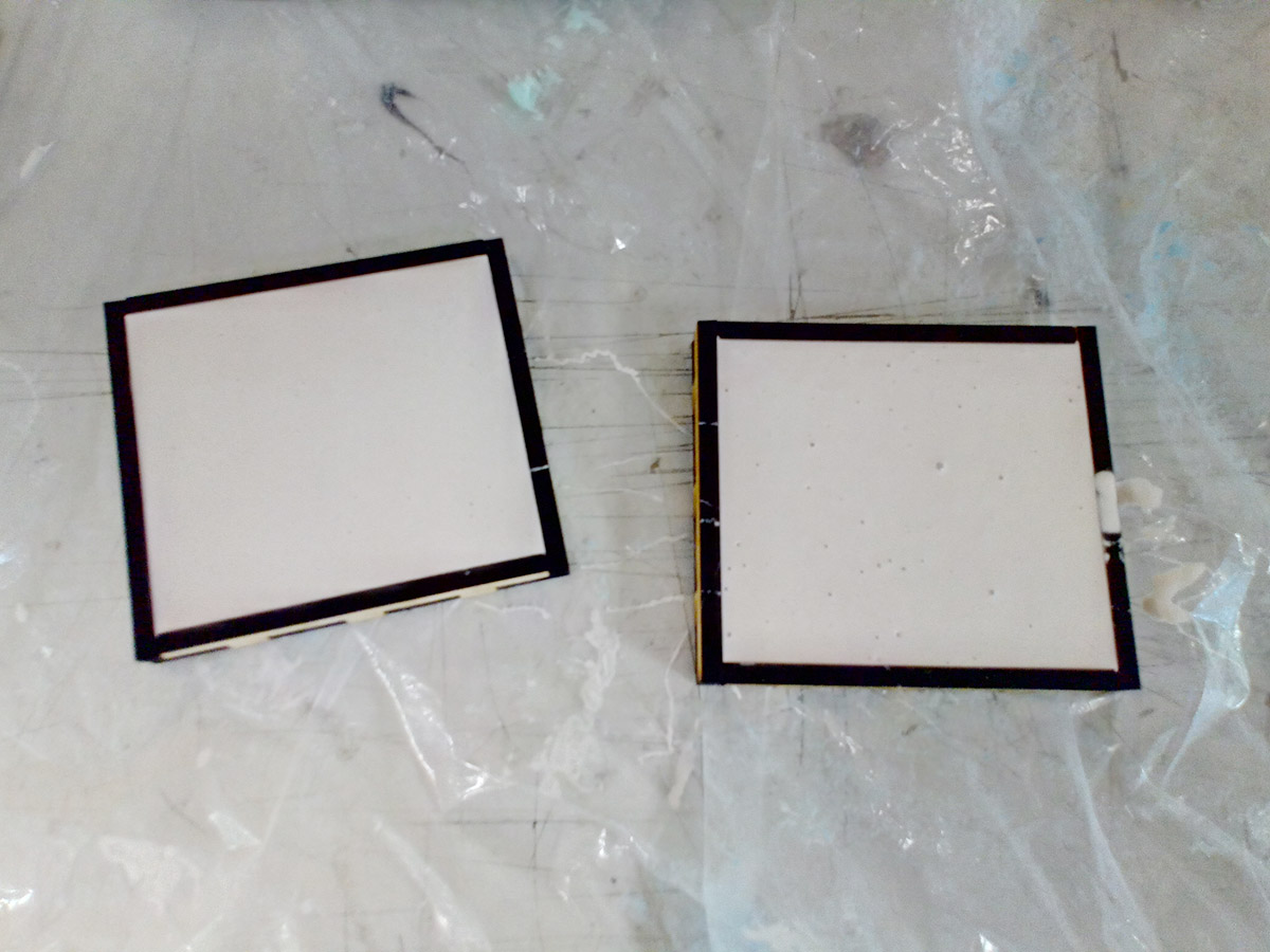
Here the result.
drying the rubber
making the base of the mold
covering the cupper
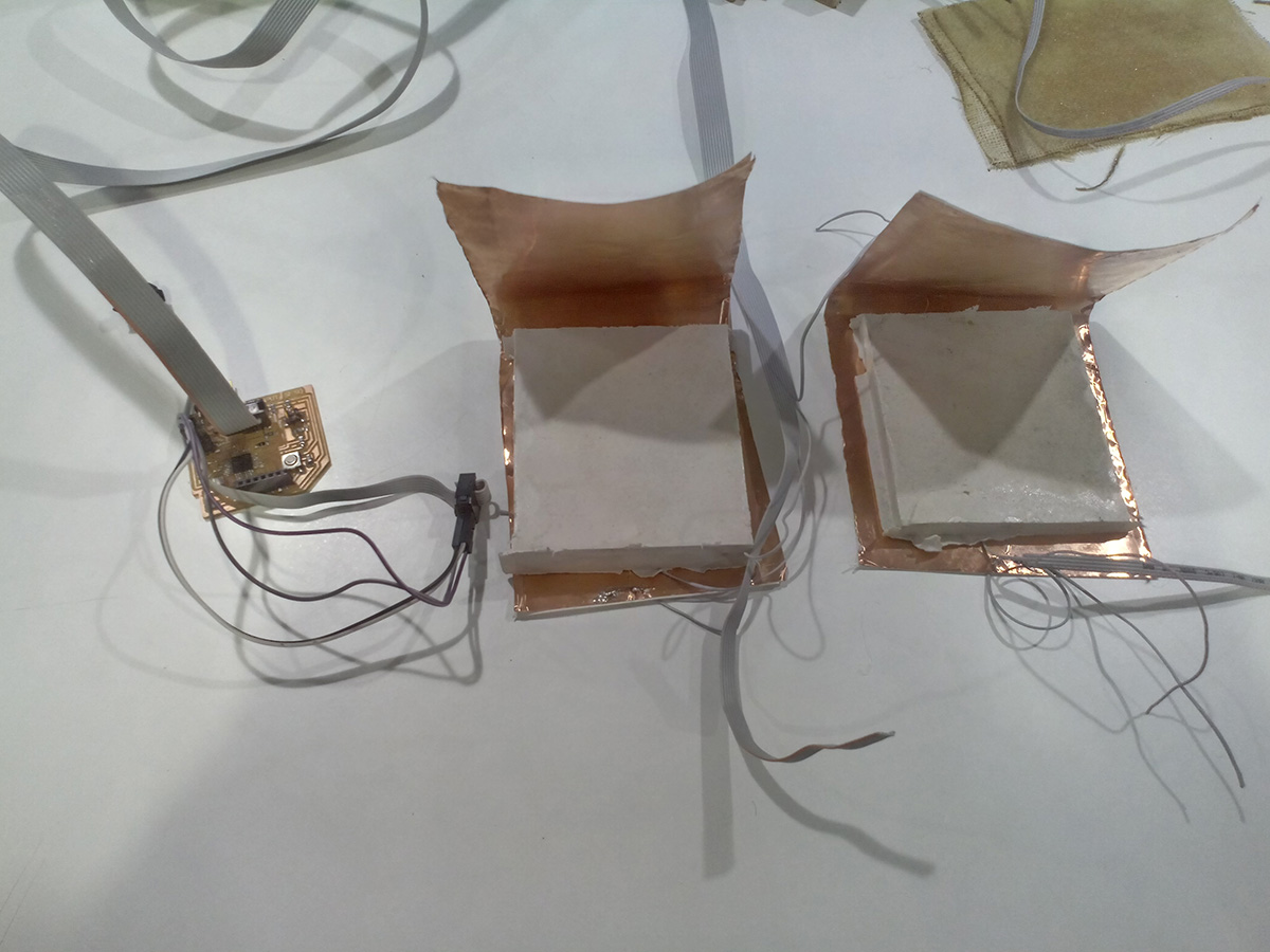
sensors finished
So that there are no movements and the copper is fixed to the rubber will use tape
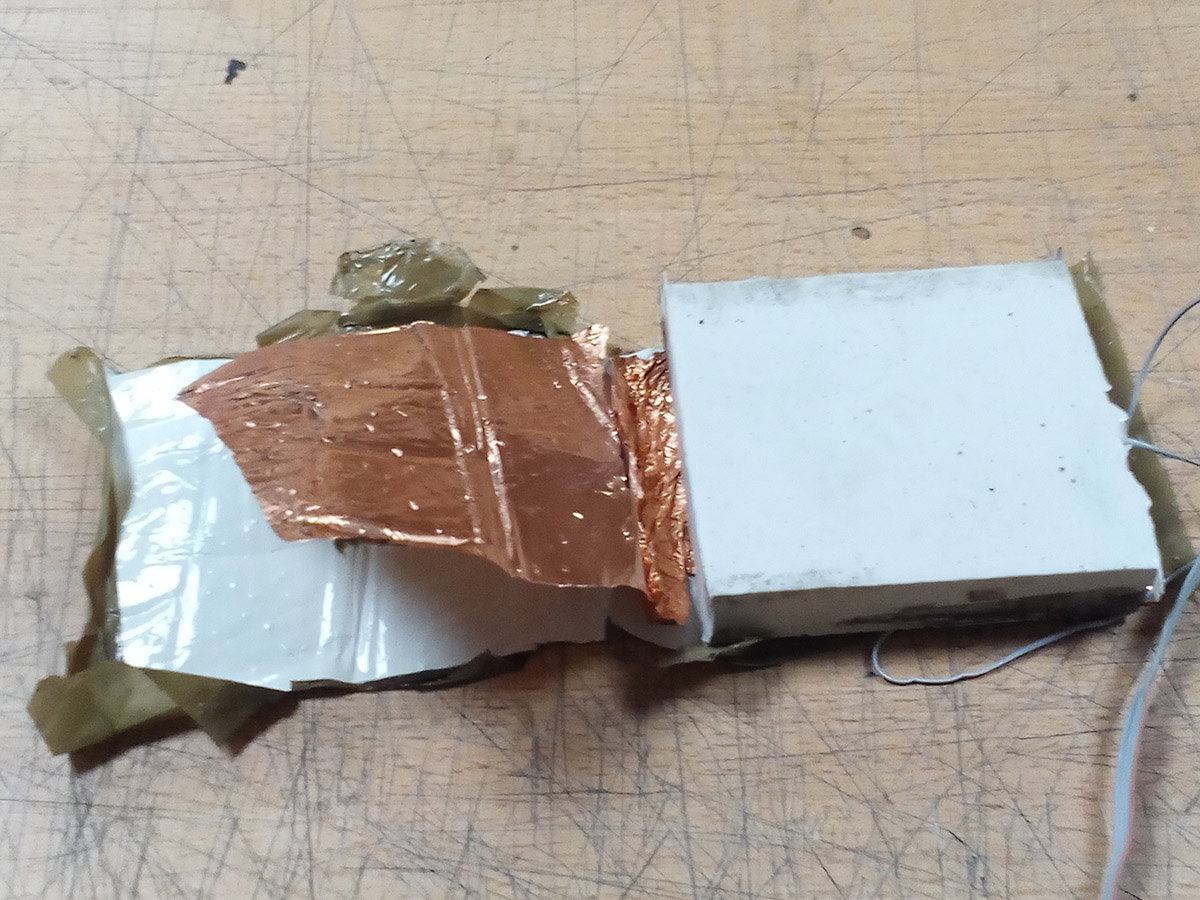
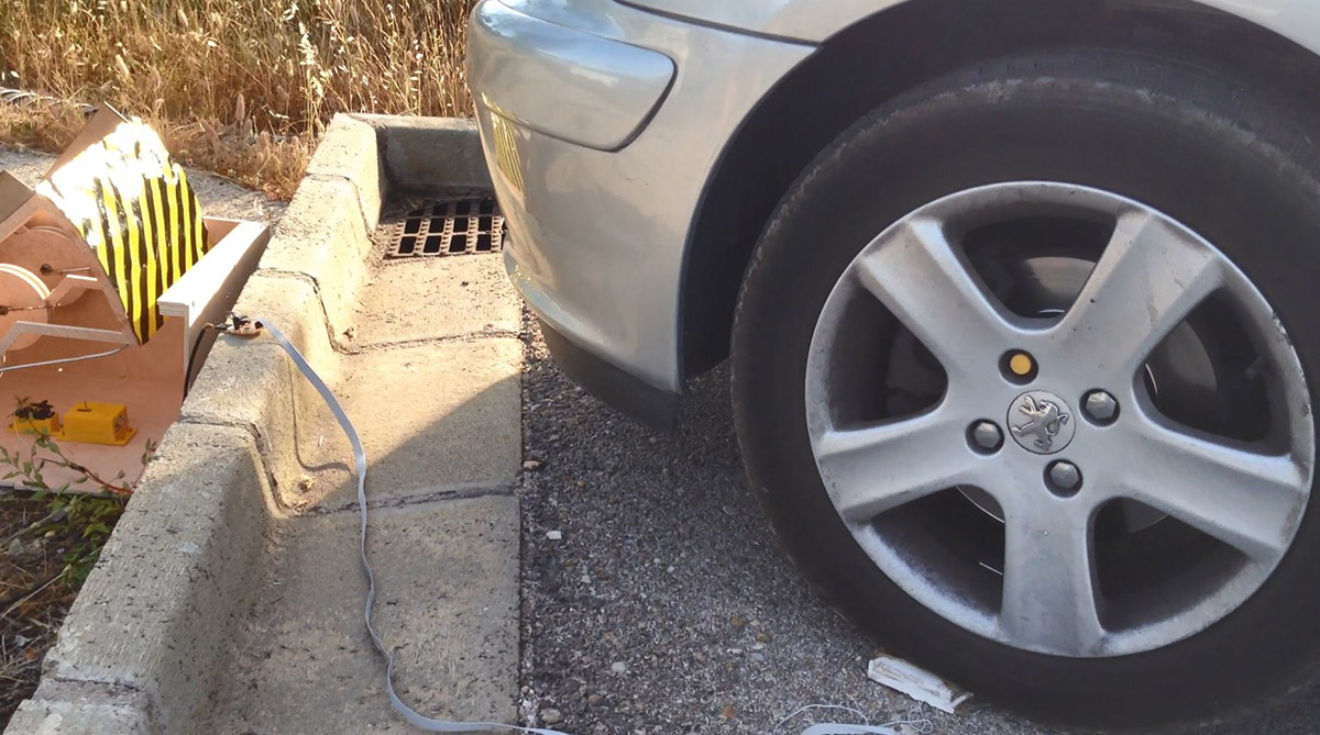
sensor of 2mm rubber, after the tests.
After passing the car several times over the sensor lost one of the cables and was destroyed.
For programming I relied on this program of Neil the hello Tx Rx written in c, through the datasheet I was able to know what I was doing in his program and to be able to do a program in arduino that did the same custom function.
This is Neil's program, and these are the screenshots to understand it.
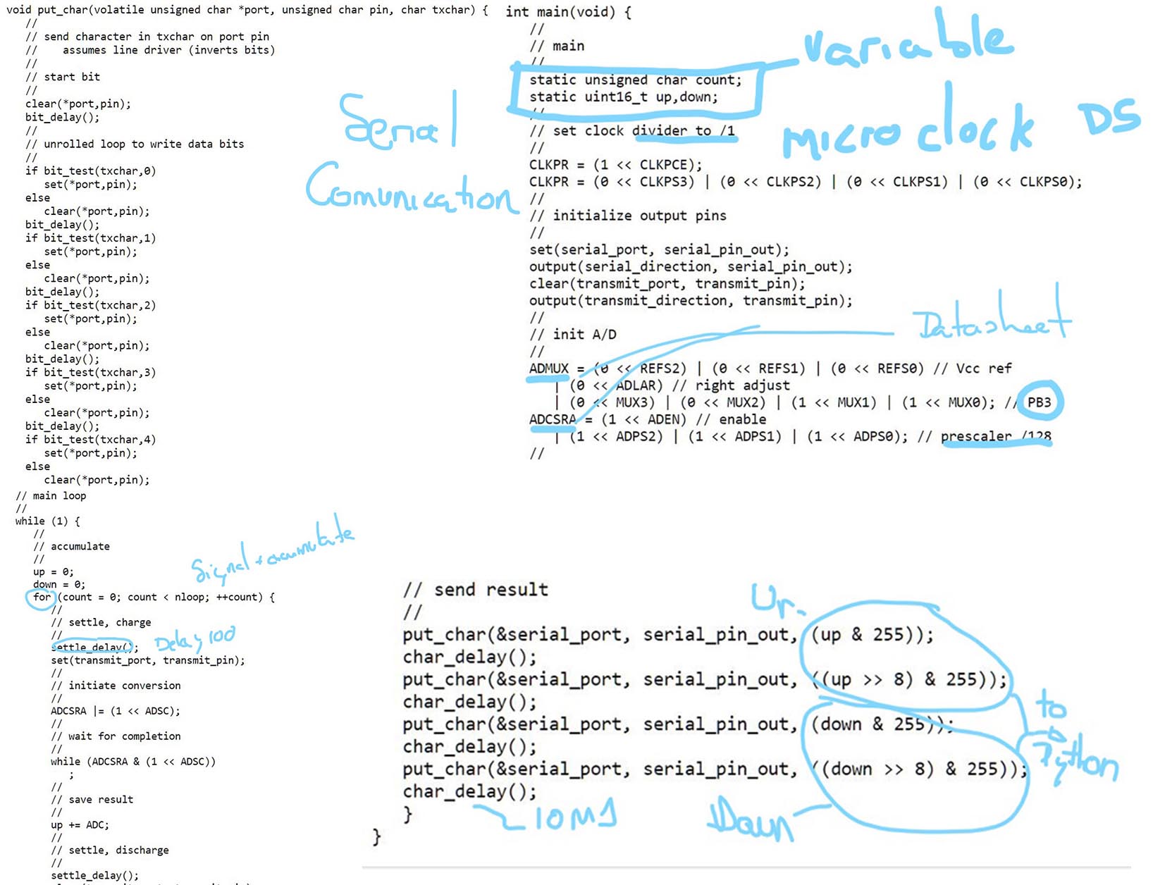
Translating the program to do it in arduino.
The program of the input what it does is prescalar the clock of the pins of the microcontroller that go to the sensor, it measures the value of the tension and it keeps doing the same with the information that arrives to him of the receiver.
Then it makes the difference of the tension between the two and writes its value in the monitor in series.
Here for the input I put an if variable, if the value is higher than a value that determined by putting 80kg (for the test was 47,000) on the sensor write the char "5" after the value read.
if the value of the reading does not reach that value or write nothing or write an 8.
These values 5 and 8 will be those that the output reads to activate in one position or another.
/* Programmed by Alvarolaroja 23/05/2017 traduced from Neil G. in C Hello TxRx */

#include <avr/io.h>
#include <util/delay.h>


static uint16_t up,down;
static uint16_t arriba, abajo;

void setup() {
  // pinMode(A3, OUTPUT);
  DDRC |= (1 << PC3);
  PORTC &= (~(1 << PC3));
  Serial.begin(9600);

  ADMUX =  (0 << REFS1) | (0 << REFS0) | (0 << ADLAR) | (0 << MUX3) | (0 << MUX2) | (1 << MUX1) | (0 << MUX0);//PC2 input
  ADCSRA = (1 << ADEN) | (1 << ADPS2) | (1 << ADPS1) | (1 << ADPS0);//prescaler 128
}

void loop() {
      up = 0;
      down = 0;
      for (int count = 0; count < 100; ++count) {
        _delay_us(100);
        PORTC |= (1 << PC3);
        //digitalWrite(A3,1);
        //arriba = analogRead(A2);
        ADCSRA |= (1 << ADSC);
        while (ADCSRA & (1 << ADSC)){
            ;}
        //up += arriba;
        up += ADC;
        //mySerial.println(up);

        _delay_us(100);
        PORTC &= (~(1 << PC3));
        //digitalWrite(A3,0);
        //abajo = analogRead(A2);
        ADCSRA |= (1 << ADSC);
        while (ADCSRA & (1 << ADSC)){
            ;}
        down += ADC;
        //down += abajo;
         }


    if ((up-down)<47000)
    {


    {
      Serial.println(up-down);
      Serial.println('5');
      _delay_ms(10);

      // Enviamos 'L' por el puerto serie (TX)

    }
     else
    {

 Serial.println(up-down);
Serial.println('8');

delay(500);
    }


         }


         }
   /*
      Serial.write(1);
      _delay_ms(10);
      Serial.write(2);
      _delay_ms(10);
      Serial.write(3);
      _delay_ms(10);
      Serial.write(4);

      Serial.write((up & 255));
      _delay_ms(10);
      Serial.write(((up >> 8) & 255));
      _delay_ms(10);
      Serial.write((down & 255));
      _delay_ms(10);
      Serial.write(((down >> 8) & 255));
      _delay_ms(10);*/
Output of my final project:
Output programming its more simple.
As a program made by me from 0, for the output is the one I will use for my final project, what I want is that when I receive a signal for the serial monitor of 5, a certain angle is moved and when I receive an 8 return to the initial position.
The command used is myservo.write () and the variables act and pos with a value in degrees. myservo.write sends the signal to the servo to move a certain number of degrees.
#include <SoftwareSerial.h>

#include <Servo.h>


Servo finalservo;

int pos = 10;
int act = 160;
int encendido=0;
void setup(){
Serial.begin(9600);

  myservo.attach(9);
}

void loop() {


  if (Serial.available()) {
    encendido = Serial.read();
    /*if (encendido == '5') {

        // servo en posicion pos
       myservo.write(pos);


      }
      */
      // Si es una 'L'
      if (encendido == '8'){

        myservo.write(pos);              // tell servo to go to position in variable 'pos'
                          // waits 15ms for the servo to reach the position*/

      delay(1000);
      }

            myservo.write(act);

 /*// for (pos = 0; pos <= 180; pos += 1)

    myservo.write(pos);
    delay(4000);
 // for (pos = 180; pos >= 0; pos -= 1)
    myservo.write(act);
    delay(1000);
  }
 }
Here you can see how works the servo with this program. This is an experiment to see a graph instead of the values in the serial monitor at week 16.
Pieces from 3d Printer (integration):
I will also use the 3d printer to make the drawer for the latch and for the servomotor, for small things that require of precision and for finished.
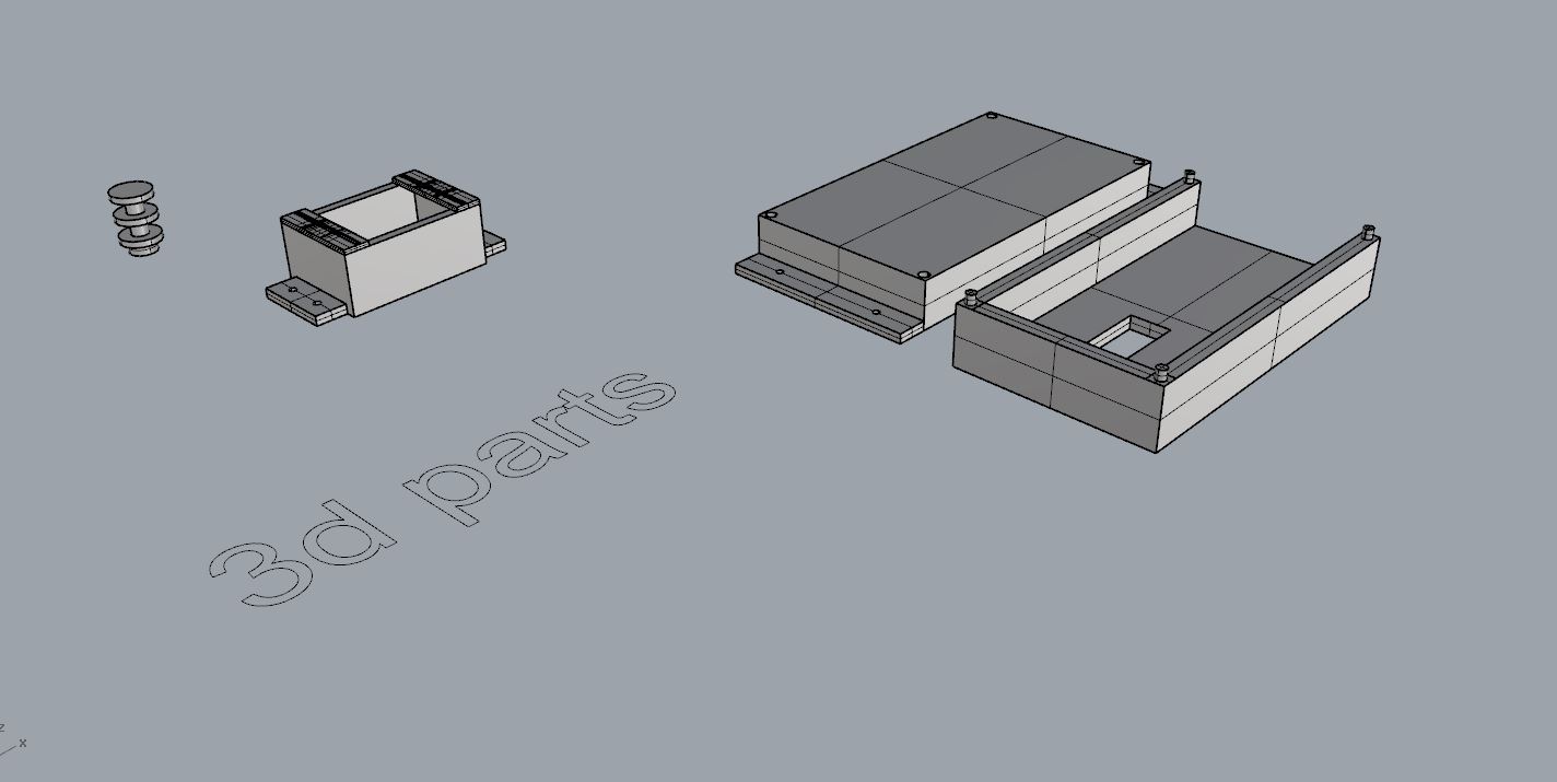
Small pieces from 3d print
I designed these pieces at the same time as I was placing the electronics and the elements that drive the spring.
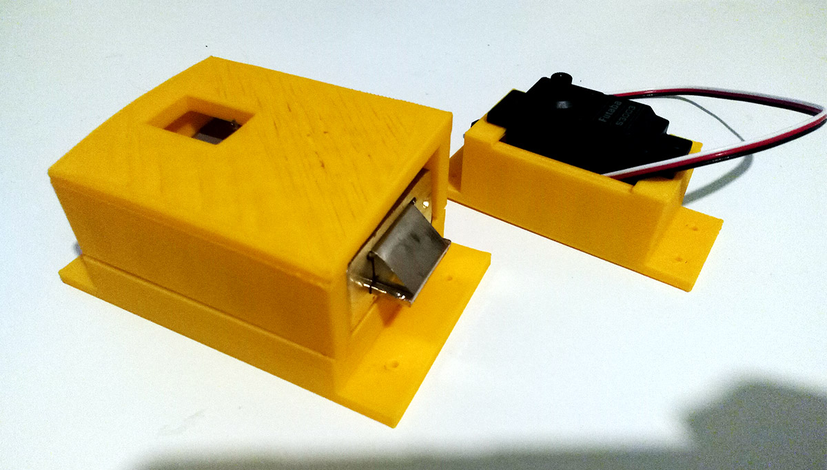
boxes for latch and servomotor.
I made several designs since I had to adjust the measurements quite to the measures of board, servo, and bolt.
In the end this was the result.
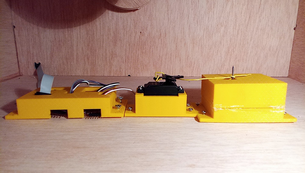
cover for boards, servo, bolt.
For more information on the BOM assignment click on the following button:
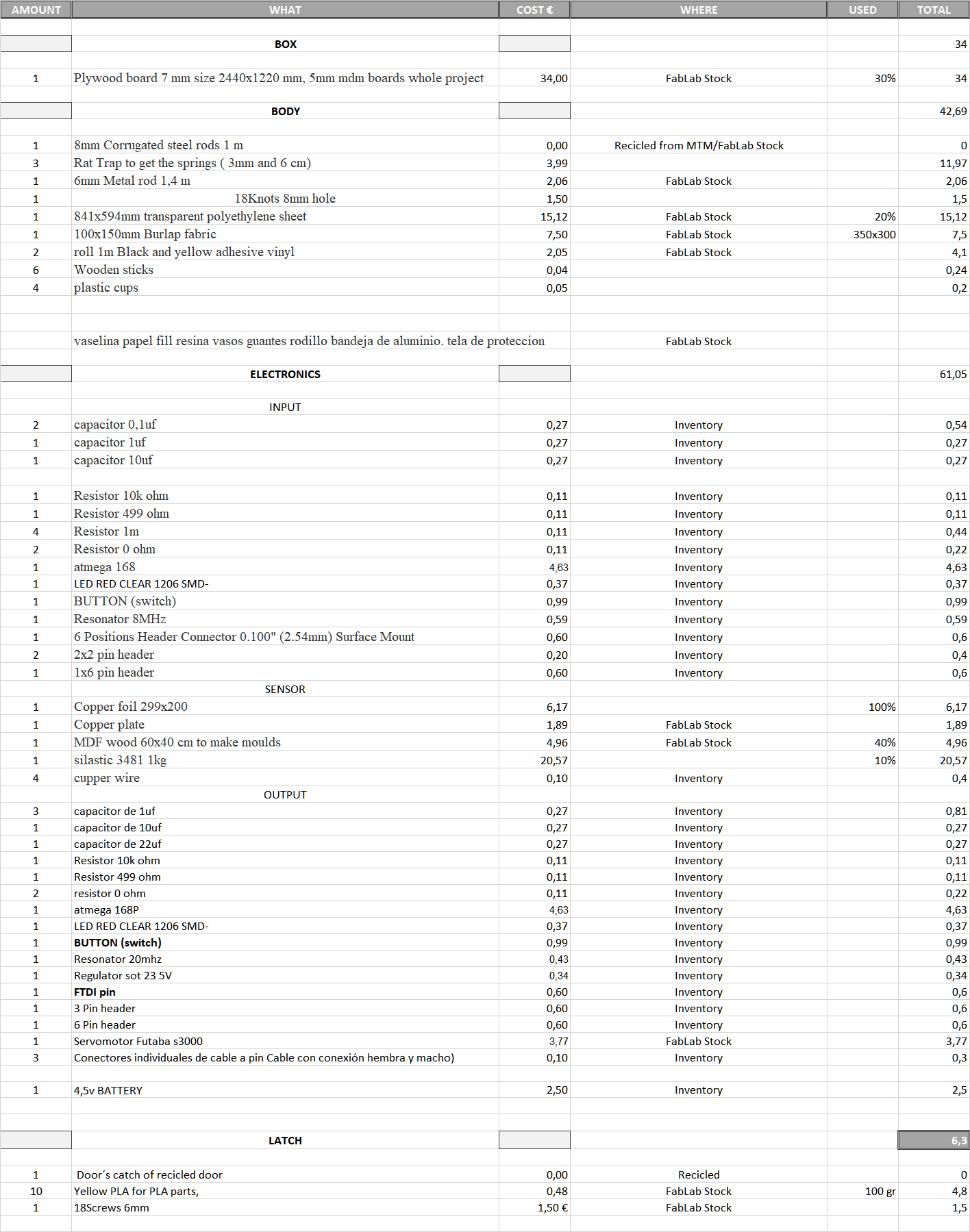
After making the final project, I show here a breakdown of the materials and components used indicating their price and the amount used, in order to approach a budget as much as possible.
Includes the licence you chose:
-- Copyright with registration in Safe Creative --
For more information on the copyright assignment click on the following button:Link to Copyright.

Copyright is a legal right created by the law of a country that grants the creator of an original work exclusive rights for its use and distribution. This is usually only for a limited time. The exclusive rights are not absolute but limited by limitations and exceptions to copyright law, including fair use. A major limitation on copyright is that copyright protects only the original expression of ideas, and not the underlying ideas themselves.
Prevents my work from being reproduced, transformed or published by third parties without obtaining prior express permission in writing from me.
This will allow me to have control of who wants to use my work and I decide freely if can or not.
As well as presenting it to competitions or future congresses of ideas or Crowfounding without fear of someone appropriating with commercial uses.
Advantages:
Greater control over where and in what terms my work is used.
Simplifies the detection and denunciation of copy of my work.
Simple to integrate in the set of other works with equal level of protection.
Accepted by society. Most people understand and use copyright licenses
Cons:
Systems for permission to use works are often slow
It is difficult to create derivative works based on the original work
Lower level of diffusion. By limiting the right to re-reproduce the works, it is more complicated that such works are multiplied by the Internet
I probably will not get rich But I will have more decision making, and it will be clear the type of license.
What does SafeCreative bring to these licenses?
Link to SafeCreative.
Reliable record of creation, authorship and license quickly
It also helps to make easier contact, thanks to a web environment, to those people who want to make use of a concrete work with its author
Facilitate a wider dissemination of works.
Conclusion:
If we believe that works can produce money and we want to have as much control as possible about where and how these creations are used, copyright is a good option. However copyright has a low diffusion on the Internet to the detriment of other forms of licenses more open.
For all these reasons I choose to have my license be copyright.
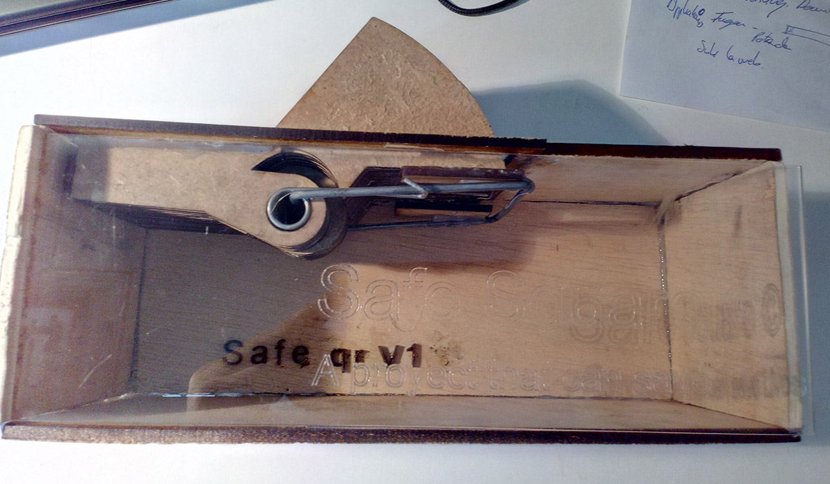
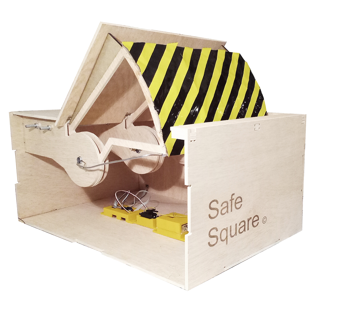
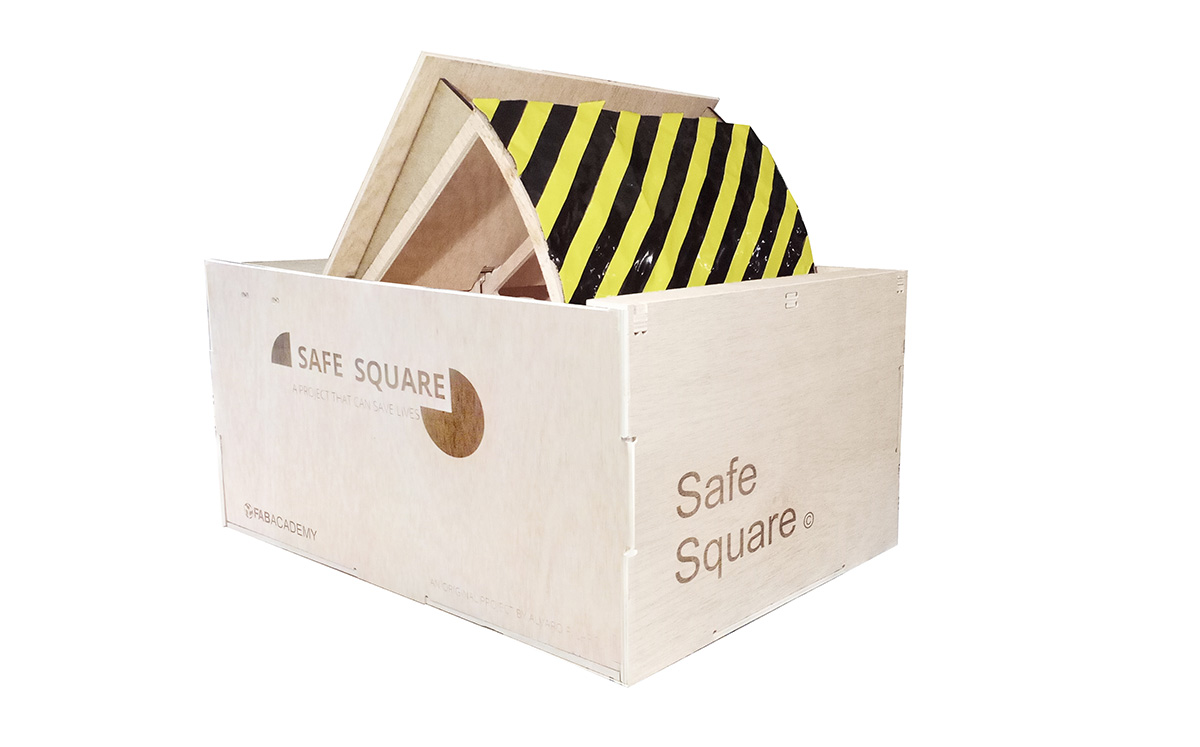
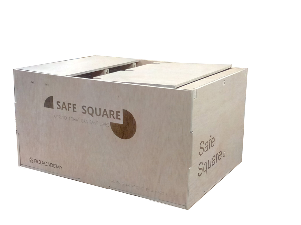
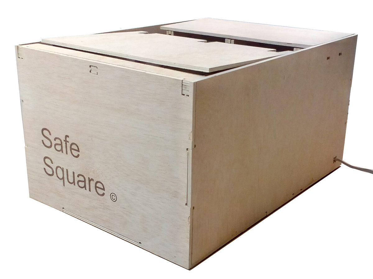
As an image of final finished product I thought of making the laser engraving on 2 of the visible faces of the project, with the name and mark of the final project.

The design is simple similar to the cover of the slide and the presentation video with my name and the project, made in photoshop and passed to image mode bitmap ready to be engraved
For more information on the Slide assignment click on the following button:

my slide from "Invention, Intellectual Property and Business Models"
other interesting videos to understand the final project:
-Presentation
Slide File
Video Mp4
- 2D cutting plans:
CNC cut file.
Burlap composite cut file.
vynil design file.
Moulds cut plan.
- 3D Printed parts:
Designfile 3dparts.
- 3D design files
Final design and cnc plans.
3D molds sensor.
- Electronic:
Networking slave1 Board
Final Input of final project
fabservo
- Programation
Finalservopf arduino
Finalservopf
- Other:
Laser engraving.