Assignments:
- Design and build a wired &/or wireless network connecting at least two processors.
- Networking needs to be more clearly defined here. Like expressing the need to have multiple controllers communicating using addressing.
--- WORKFLOW ---
I will try to follow this workflow for this week. 1. Understand the types of communications and see what I need to communicate in serial or i2c.
2. Make a schematic of the type of communication I want and the schematic of the board.
3. Design the board.
4. Make it.
5. Name them and programming the communication.
6. Test the communication of my boards.
1. Understand the types of communications and see what I need to communicate in serial or i2c.
Rs232 and rs 485 are standards for how a physical signal will be transmitted from one environment to another, how many wires it has, how the data is transmitted and what voltage.
232 is very old, nullmodem, is an inverted protocol, +3 to +15 -3 to -15, small sizes over 5m is not recommended.
422 and 485 the difference lies in that the 422 can only speak one device and in 485 all at the same time.
All can make receiver and transmit but controlled the connection bus.
It is a differential protocol, which means that if at one point there is more tension than another it is a 1 or a 0.
What is measured is the difference so you only need 2 cables, which are not referenced to ground,
Can be used for very long distances 1km or more, resistance has to be 120ohm, if there is electromagnetic interference it is compensated since it measures the difference only.
The I²C is designed as a master-slave bus. Data transfer is always initialized by a master; the slave reacts. It is possible to have several teachers in a multi-master mode, in which two teachers can communicate with each other, so that one of them works as a slave. The arbitration (control of access in the bus) is governed by the specifications, in this way the teachers can take turns.
2. Make a schematic of the type of communication I want and the schematic of the boards.
There are several ways to communicate in serially across multiple devices.
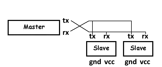
The Master-Slave connection consists of a device that communicates with Tx and Rx with others in series.
The function of the Master is to send information to the Slaves so that when they receive it activate their programmed function.
The master to send in series has to connect its Tx to the Rx of the rest of devices, and its Rx to the tx of the rest, so that they receive what it transmits and can receive what the slaves transmit.
The other devices will be connected Tx with Tx and Rx with Rx.
The Master- can be the PC or a board dedicated to it. (in this assignment I choose to be the PC)
Slave - The other boards connected to each other in series, the programming is very similar only I change the pins that we want to activate.
What I need for the final project is to communicate my input and output board with the master board.
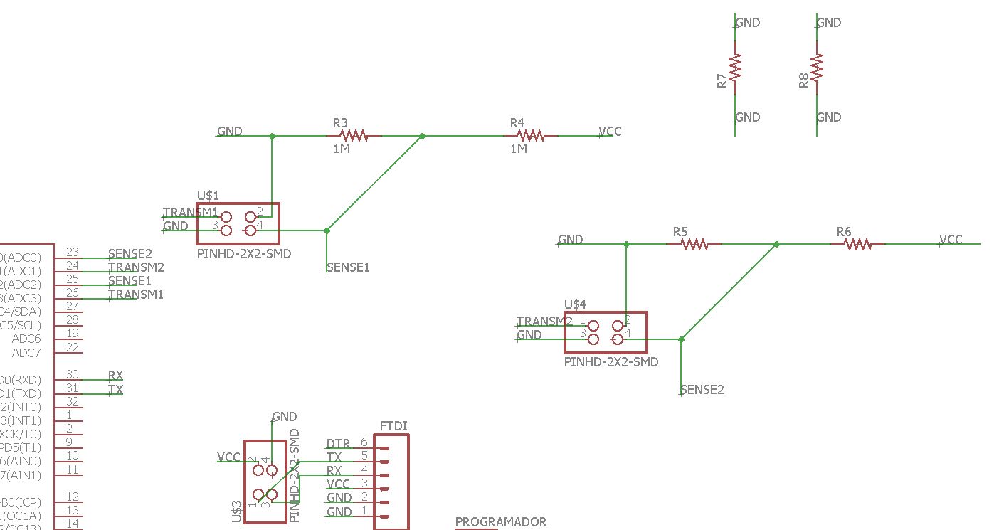
We will communicate the boards using serial protocol 485.
This will be the operating scheme.
This will be the schematic design of the master board.
All plates must have a 4-pin module connected to tx rx gnd and vcc.
Master (PC) Slave1 (slaveboard) Slave 2 (input SF SQ).
3. Design the boards.
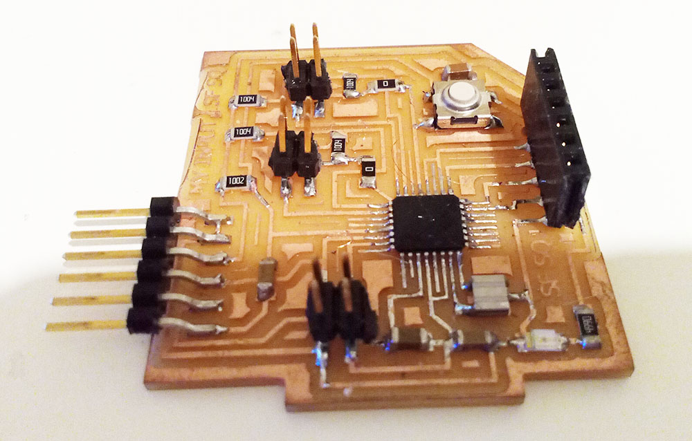
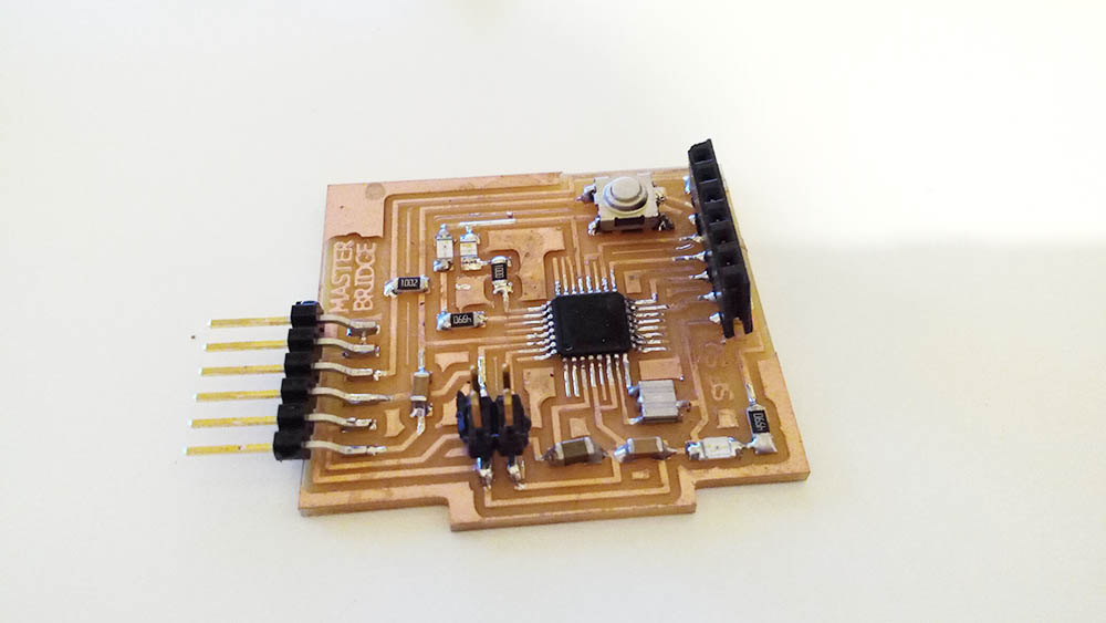
For the first board I designed, slave 1, I relied on the input board.
I changed the components of the sensor by 2 leds to be able to perform functions in the communication.
Also add a Rx Tx communication pin to connect in series with the next slave, and the ftdi connection to be able to connect to the Master (PC).
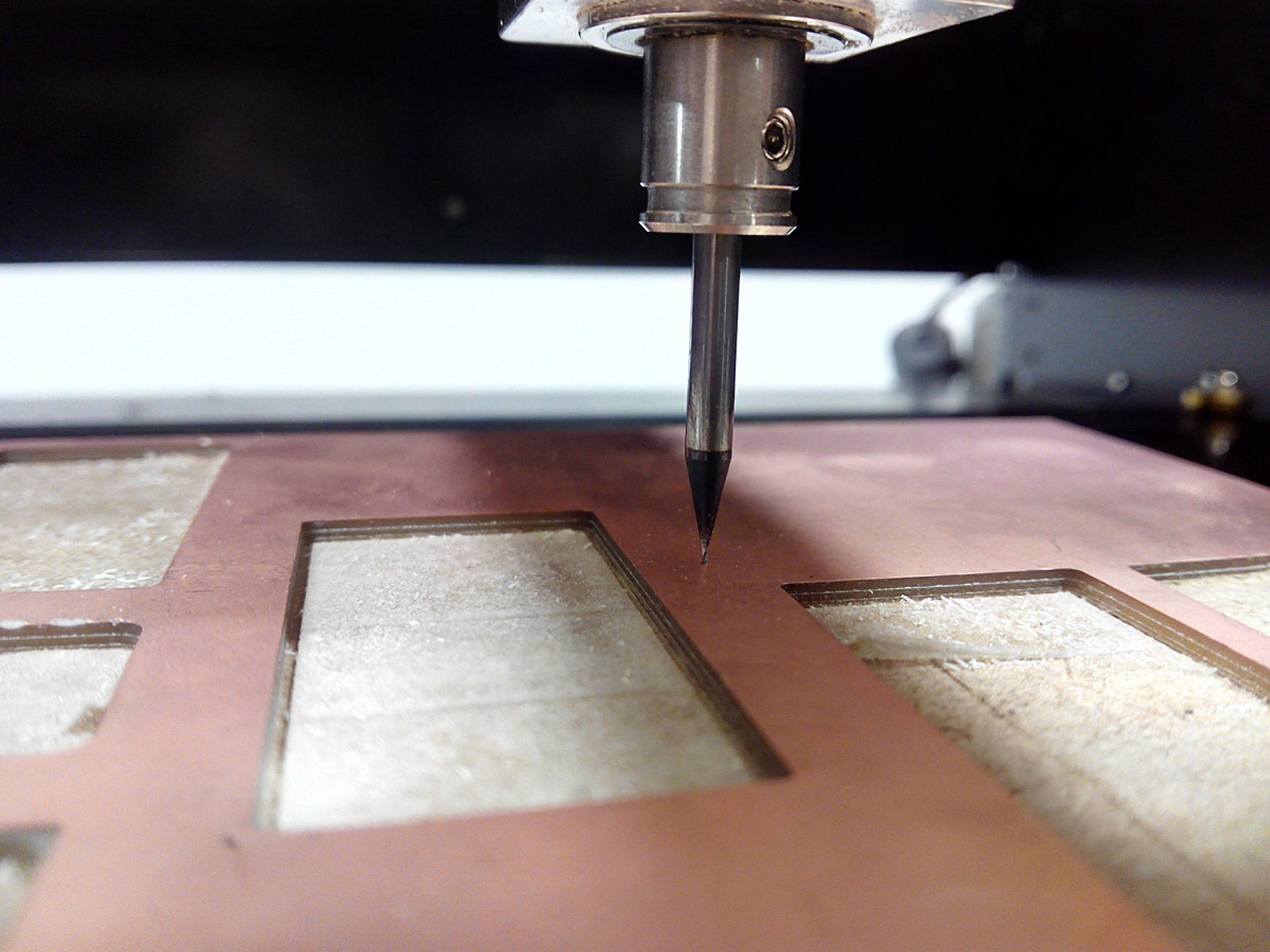
As in other exercises we use the design rules to check errors before milling.
And I did the traces thinking about this.
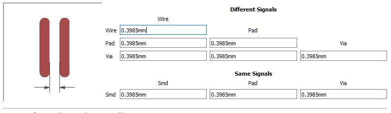
Design rules

Width of normal wire, (near the microcontroller used a width of 0.3048).
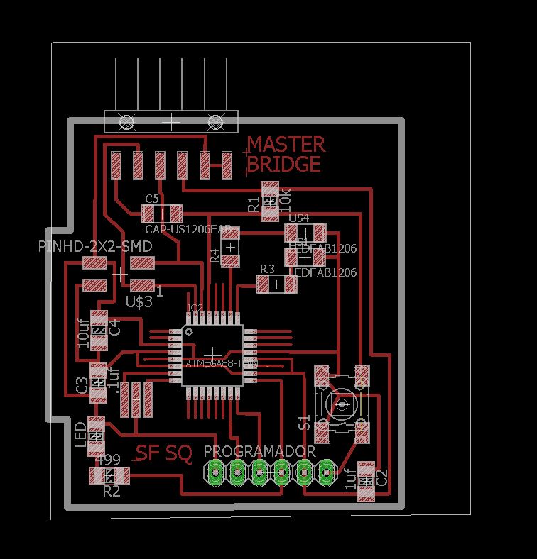
Networking board:
This is the schematic board design:
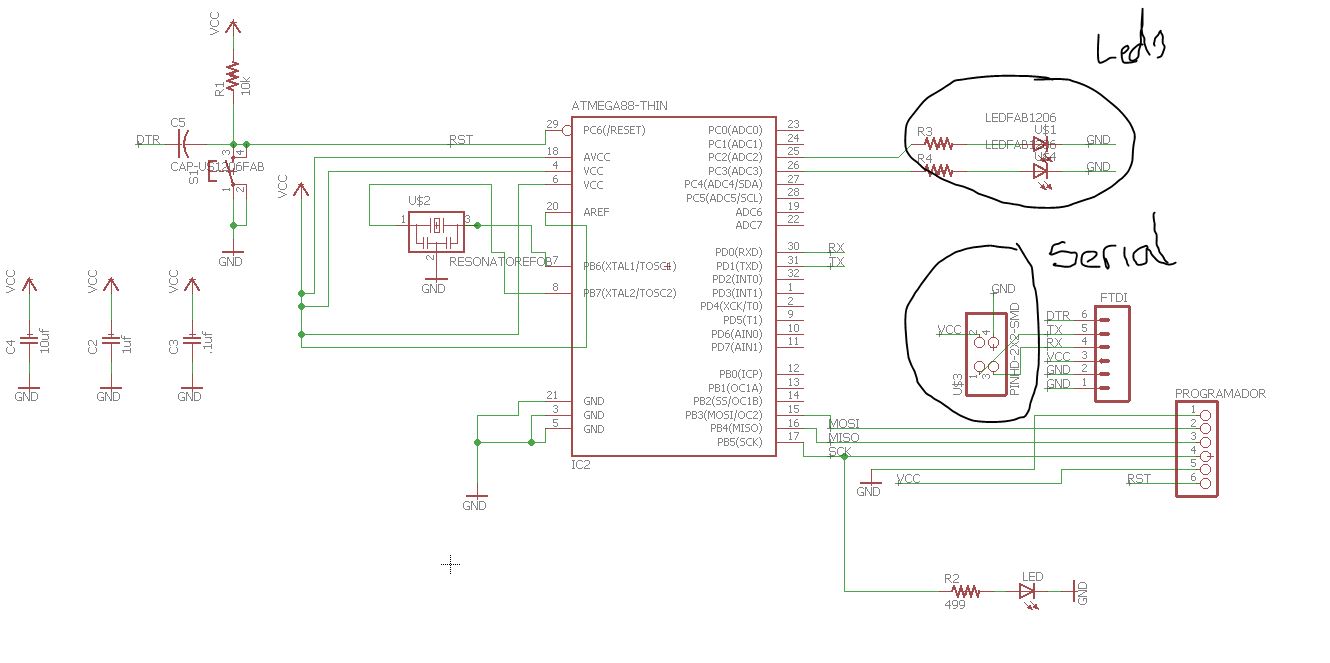
serial module,and information leds.
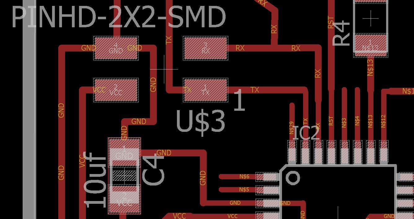
first place the serial module
then the 2 leds, one blue and one red,Final board.
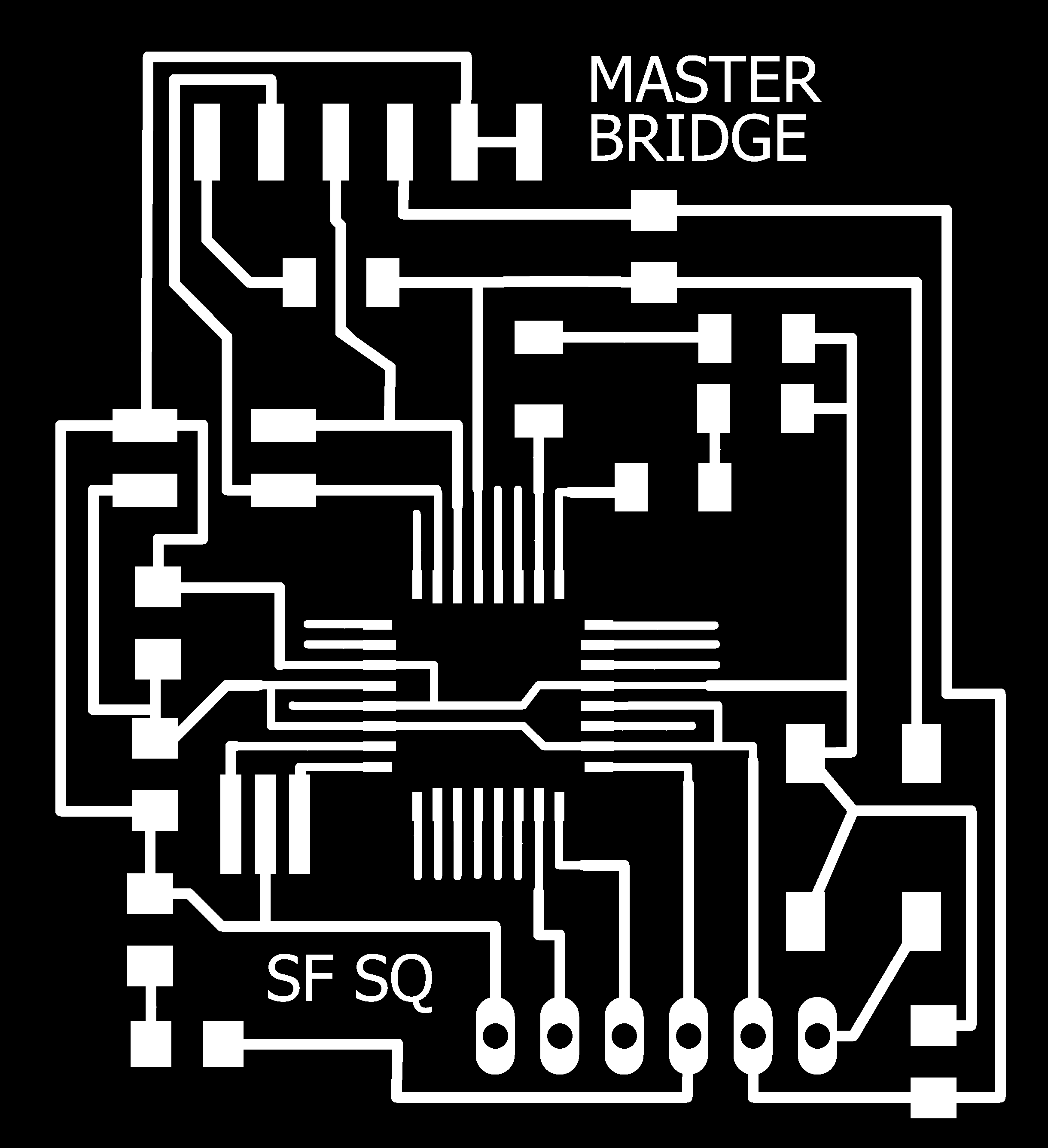
Traces

Pads

Frame
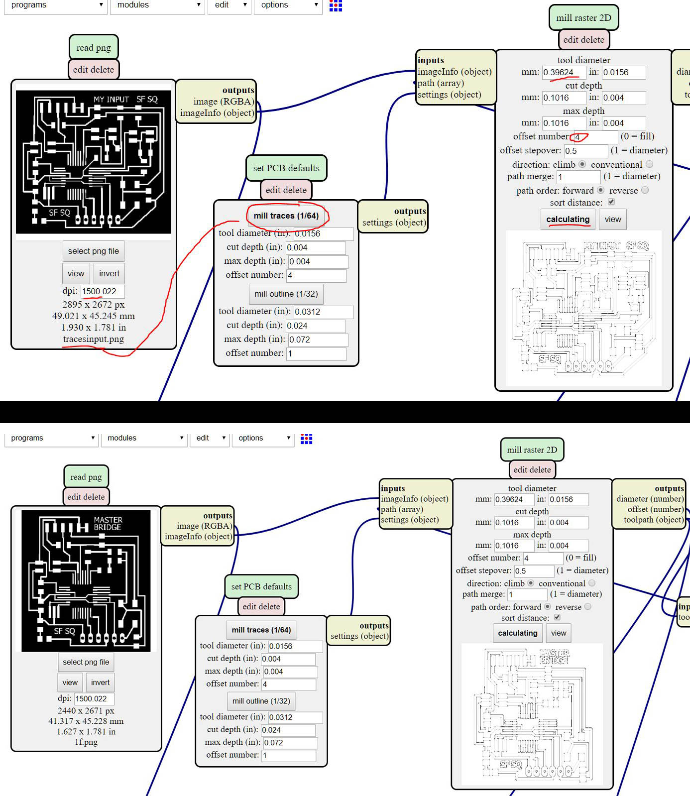
Input Board for my Final Project:
Then I made another board, in this case I made the sensor of my final project, based on the input board but different from that of week 13, I made another board in this case with the possibility to connect 2 capacitive sensors and a serial connection to send and receive data.
I add another space for the sensor, which has to be connected to the nearby pins, the function of having 2 sensors of these could be calculate in addition to a large weight calculate the speed between two sensors separated a distance.
Schematic
On the other side I also add the pin for serial communication.
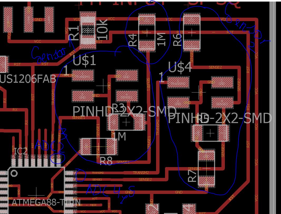
New sensors
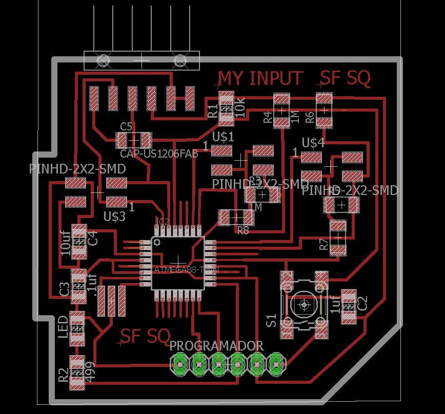
Final Input board
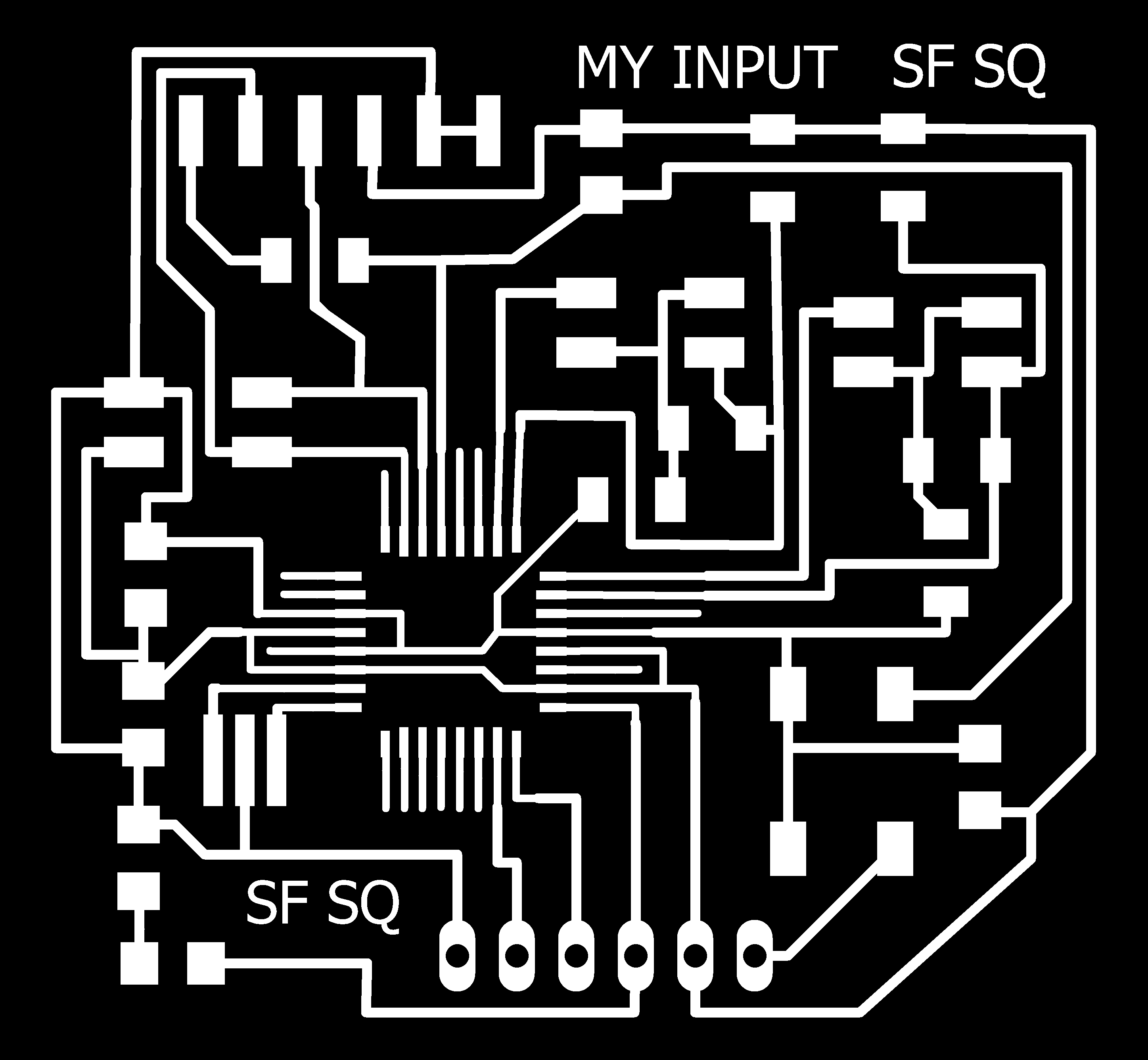
traces

pads

Frame
4. Make it
To do it I did not have any problems, I did it in the same way that I made other boards. When soldering this board had to place the leds in the correct way, either looking at the datasheet or using the voltmeter.
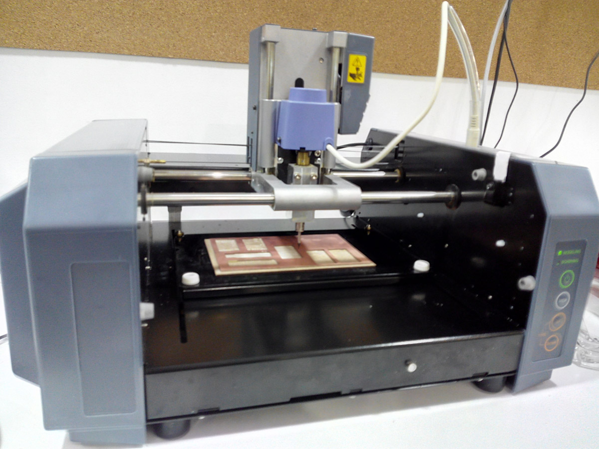
Preparing the mdx-20 for pcb milling.
The origin is ready.
I prepare the file in Mods.
And this is the final result:
Input board
Networking board.
when I went back to do the output of the final project, I also put the serial communication so that the input and the output could be communicated.
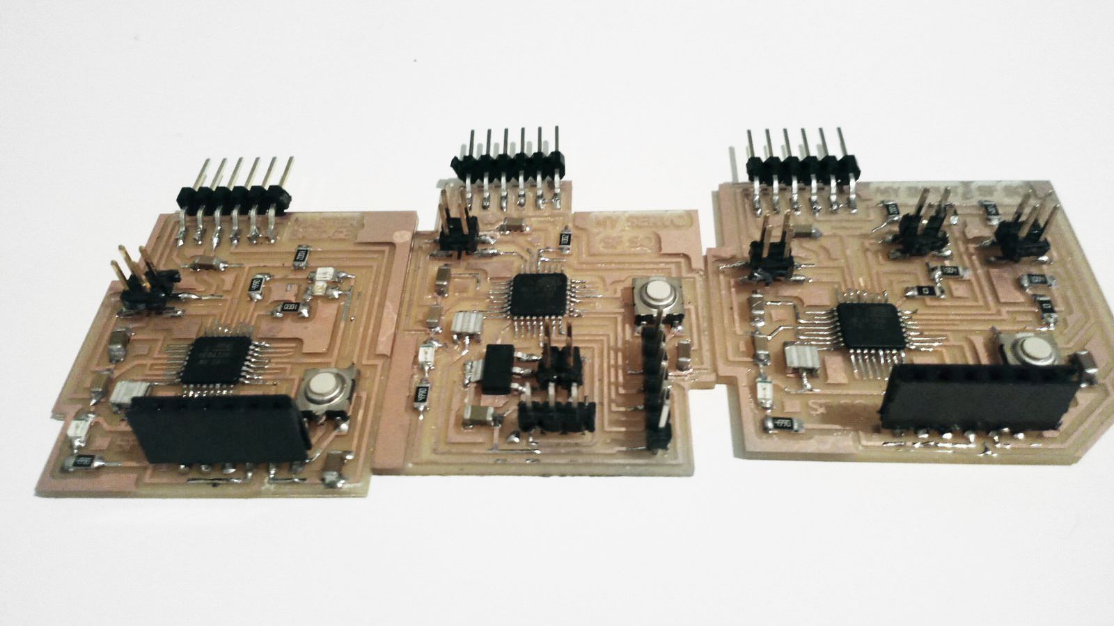
My 3 final boards that can be network in serial.
5. Name them and programming the communication.
To perform the communication I have to make a program and use control structures as if.
For this I want that when communicating with a plate only that one performs a function and that when I communicate with the other it only performs a function.
I will make each board identify with a number, for example 2 and 3, and when writing on the serial monitor one of these numbers only receive the information one of them and communicate with the computer.
Programming slave 1:
I will make slave 1 flash 1 of its LEDs for 1 second and the other will keep it on, then when from the serial monitor enter the number 2 that is its ID will light the led of pin A2 and will send by the console "node 2".
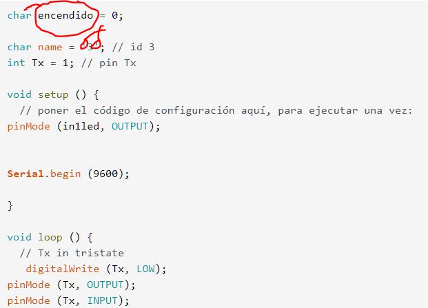
int in1led = 13;
int in2led = A2;
char encendido = 0;
char name = '2'; // id 2
int Tx = 1; // pin Tx
void setup () {
// poner el código de configuración aquí, para ejecutar una vez:
pinMode (in1led, OUTPUT);
pinMode (in2led, OUTPUT);
Serial.begin (9600);
}
void loop () {
// Tx in tristate
digitalWrite (Tx, LOW);
pinMode (Tx, OUTPUT);
pinMode (Tx, INPUT);
if (Serial.available ()) {
encendido = Serial.read ();
Serial.println (encendido);
if (encendido == name) {
pinMode (Tx, OUTPUT);
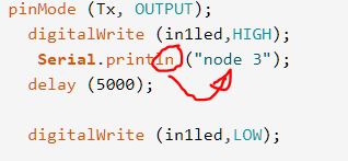
digitalWrite (in1led,HIGH);
digitalWrite (in2led,HIGH);
Serial.println ('node 2');
delay (1000);
digitalWrite (in1led,LOW);
}
}
}
Programming slave 2:
In this other case I will have the slave 2 flash its single LED for 5 seconds, then when the serial number is entered the number 3 that is its ID will light the led of the pin 13, also send by the console "node 3".
int in1led = 13;

char encendido = 0;

char name = '3'; // id 3
int Tx = 1; // pin Tx

void setup () {
  // poner el código de configuración aquí, para ejecutar una vez:
pinMode (in1led, OUTPUT);


Serial.begin (9600);

}

void loop () {
  // Tx in tristate
   digitalWrite (Tx, LOW);
pinMode (Tx, OUTPUT);
pinMode (Tx, INPUT);


 if (Serial.available ()) {
    encendido = Serial.read ();
    Serial.println (encendido);
        if (encendido == name) {
pinMode (Tx, OUTPUT);
  digitalWrite (in1led,HIGH);
   Serial.println ("node 3");
  delay (5000);

  digitalWrite (in1led,LOW);


    }

}


 }
With this I will be able to control with which of the two boards I communicate and that these are answered by the monitor in series.
6. Test the communication of my boards.
I connected the 2 boards through a header with 4 wires Rx - Rx Tx - Tx GND - GND VCC - VCC and one of the plates connected by FTDI to the pc.
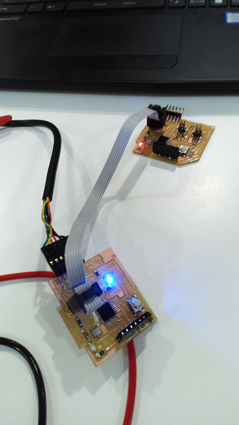
2 boards connected.
PROBLEMS:
I had problems with the programming, they were my mistakes, for example I had the problem that the word on was a numeric variable instead of a variable char, besides I did not put quotation marks and I was a while seeing that it was what I had programming failed.
Problem with quotation marks and ASCII.
Another error mainly programming, was that I wanted the board to communicate through the serial port, individually communicated but when it was connected in serial did not appear the ID, for example I pressed 2 and the serial monitor did not appear "node 2 "commanded by the programming of the board 2.
The failure turned out to be in programming when not putting Serial.Println, the board sent the indormation but in the screen of visualization this detail could not be seen.
Problem with prgramation, monitor serial and comunnication with board.
FILES:
Networking slave1 Board
Final Input of final project
Programs