Assignments:
- Add a sensor to a microcontroller board that you have designed and read it.
--- WORKFLOW ---
I will try to follow this workflow for this week.1. Design a input circuit.
2. Produce it.
3. List of components.
4. Solder all the components and test it.
5. Program something simple with the sensor (testing the board).
6. Program a pressure sensor.
--- 1. Design an input circuit ---
What I want to fabricate is an inexpensive pressure sensor, pressure or weight sensors, when they are for high values, are extremely expensive.
For my project I will need a homemade sensor that detects a high weight like a car, van or truck.
To measure the pressure in the class of input devices, there is a type of capacitive sensor.
This sensor works with two copper plates, which when approached generate a voltage differential that oscillates depending on they approach more or less.
Placing an elastic material can be measured if the copper gets more or less closer and therefore know if there is a high weight or not crushing the sensor.
- To design this circuit I will rely on two exercises:
- The previous output exercise, in which I modified a fabkit to control a servomotor.
- input assignment there is a pressure sensor called hellotxrx.
output exercise
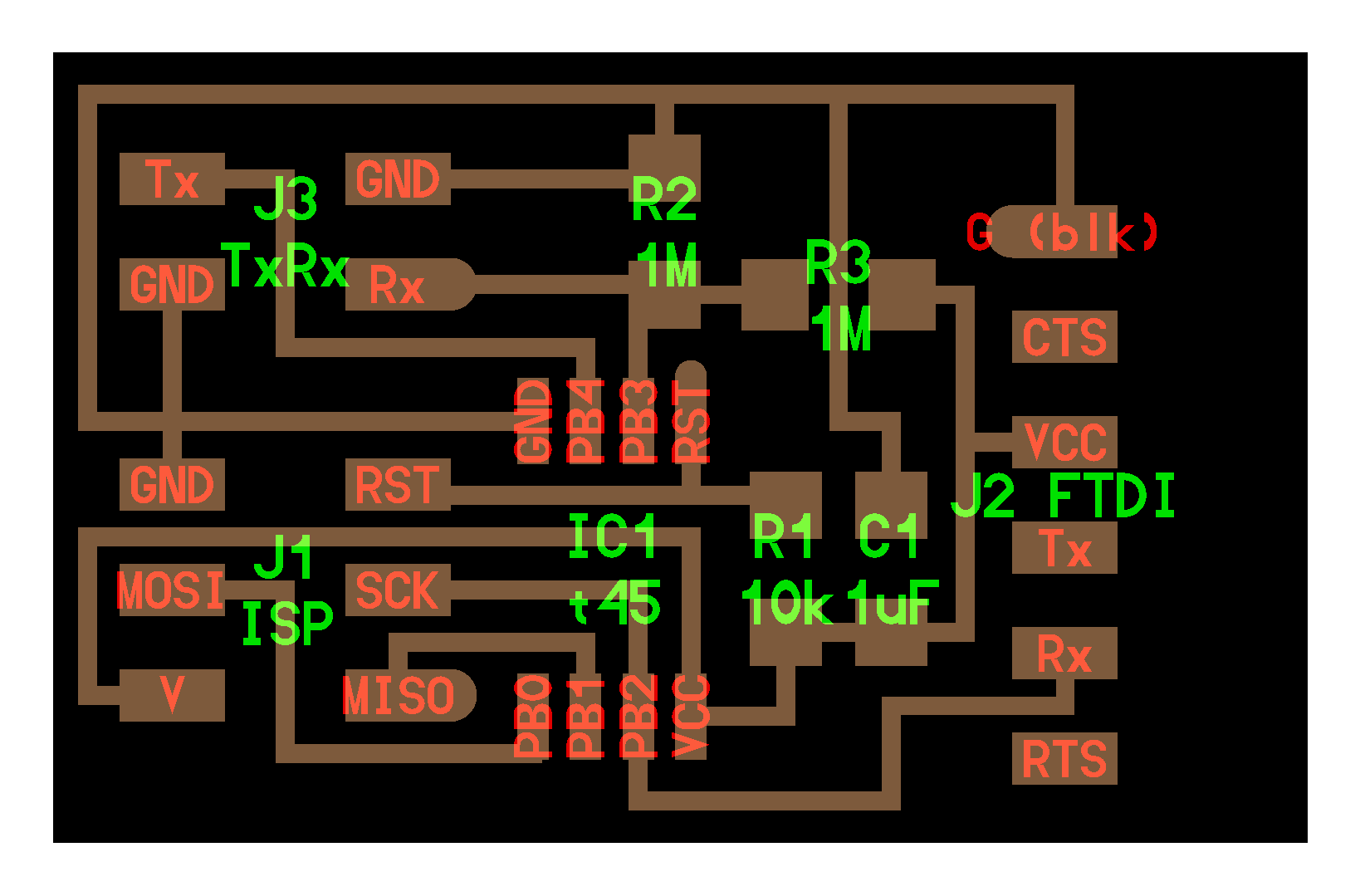
hellotxrx.
I do changes in the new board adding the sensor I'm going to erase the servomotor I will not need on this board, and I need to add a Tx,Rx,Vcc,GND output to connect the new sensor.
Question1: What are I trying to read ???
What I am trying to read is the voltage difference between tx and rx of the plate, measured from some ADC pins.
By programming these voltage difference values can be interpreted as a pressure measurer.
The crushing of the copper plates leaving the Tx and Rx causes the voltage difference in the ADC pins to be higher or lower, by measuring this variation under specific conditions the weight can be approached or a high weight can be detected.
Neil explains it in the video of the input class.
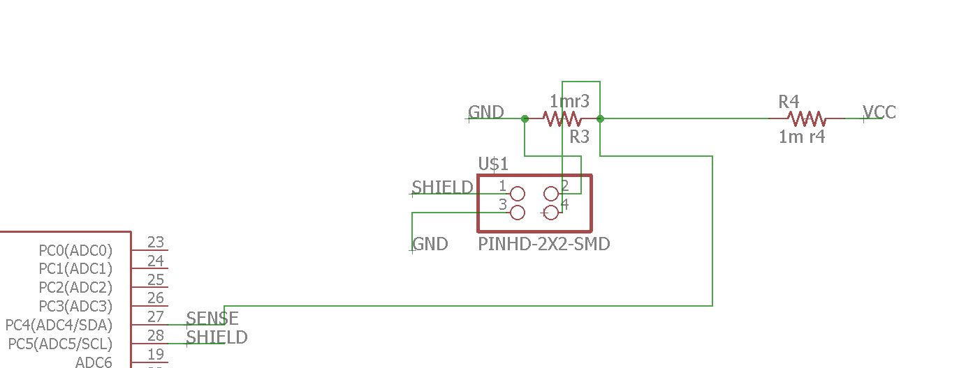
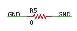
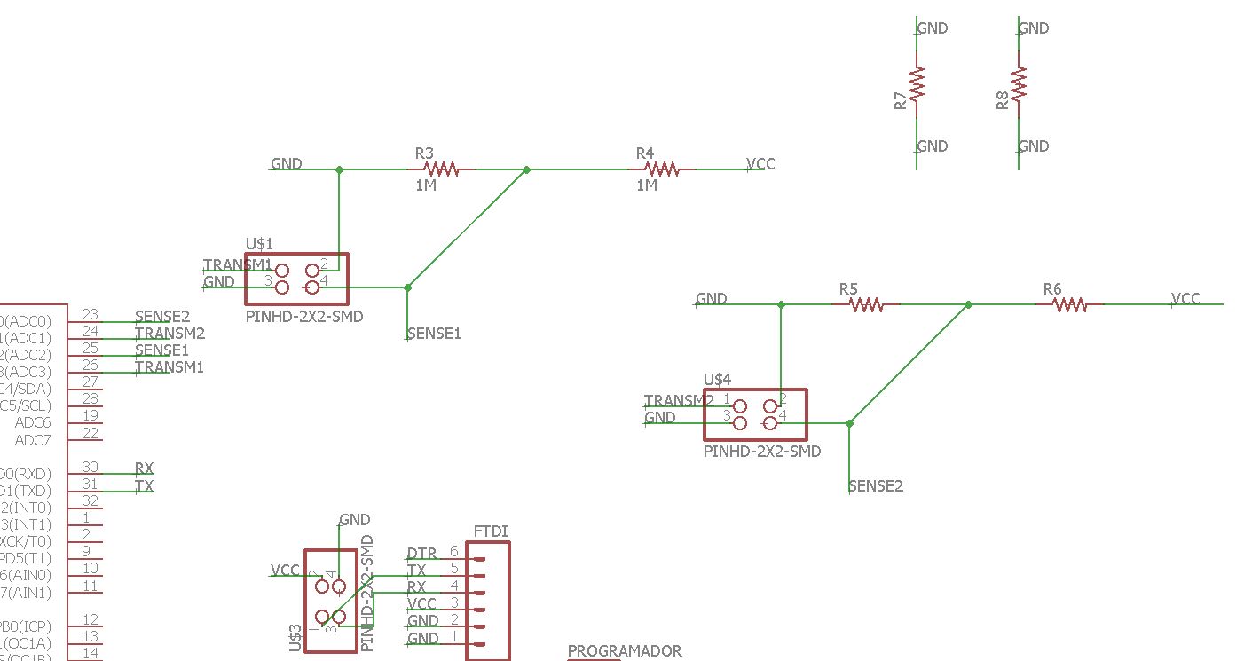
the last schematic for a pressure capacitive sensor.
This is the final schematic where you see all the components that I will use.
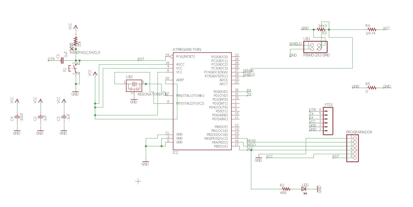
final schematic.
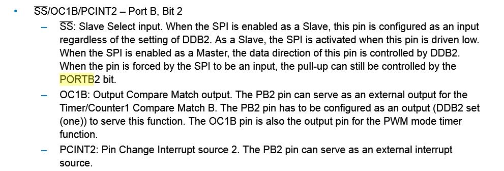
To know which microcontroller pins I had to use to receive the sensor information I looked at the datasheet.
This picture shows what types of pins are.
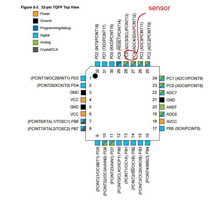
description of the pins in the datasheet.
What is an ADC?
Analog digital converter (ADC)
A microcontroller only understands digital signals (1's and 0's), so in order to read analog signals we need Analog to Digital (ADC) converters.
How an analog-to-digital converter works:
The converter has a resolution of 10 bits, returning integers between 0 and 1023. Atmega 168 analog pins also have all the functionalities of the digital pins. Therefore, if we need more digital pins we can use the analog pins.
A microcontroller only understands digital signals (1's and 0's), so in order to read analog signals we need Analog to Digital (ADC) converters. This conversion consists of the transcription of analog signals into digital signal, for the purpose of facilitating their processing (coding, compression, etc.) and making the resulting signal (digital) more immune to noise and other interferences to which the signals are more sensitive analog signals.
Or in my case it serves to read a sensor and give you values not 0 and 1 if not a much greater oscillation depending on what you capture.
For more information you can read in the datasheet of the processor the options with pins ADC, page 305 of datasheet of the ATmega 328.
I have chosen for the sensor the pins 27 and 28 Adc4 and Adc 5.
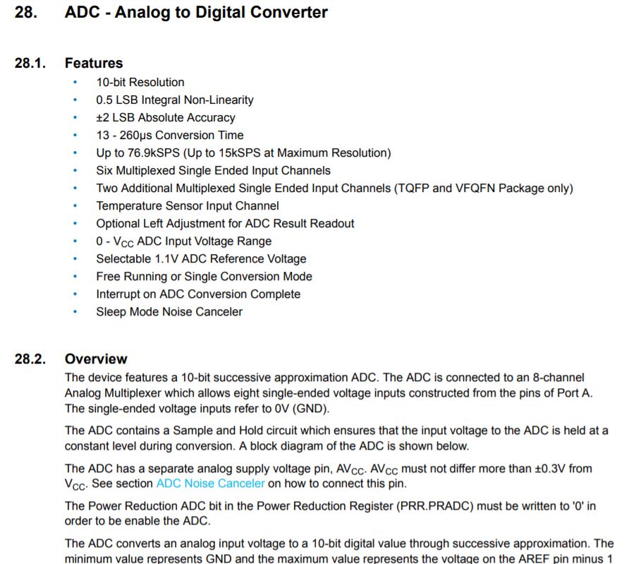
ADC section.
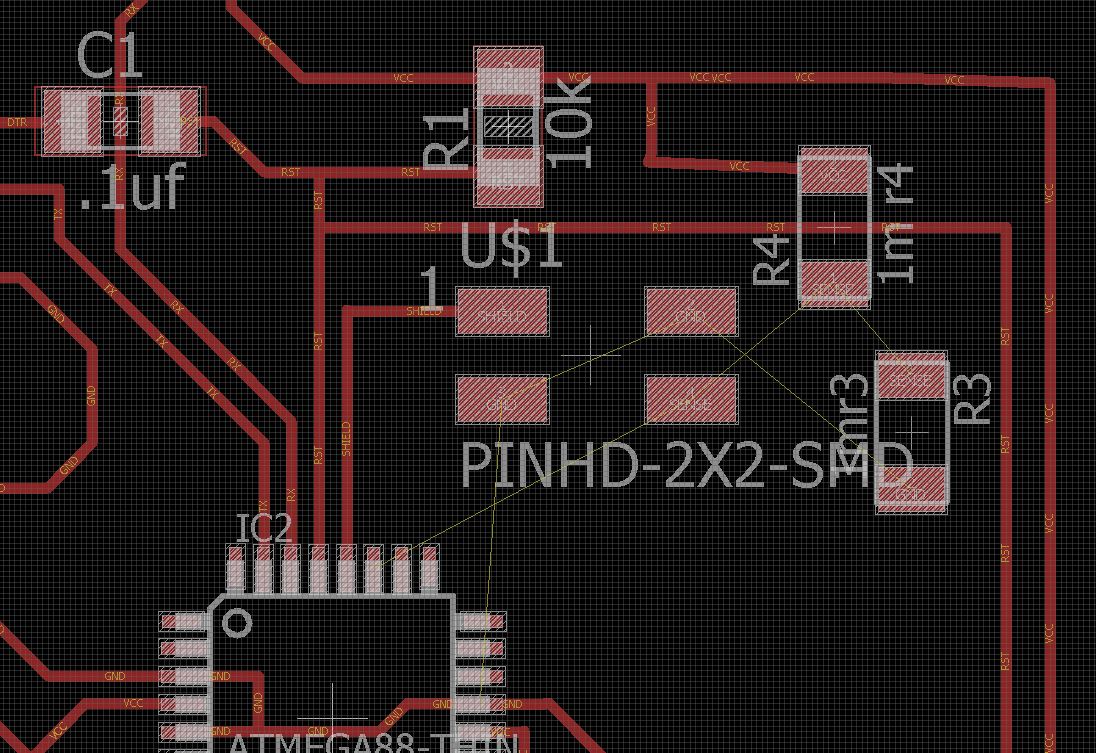
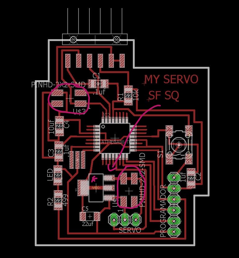
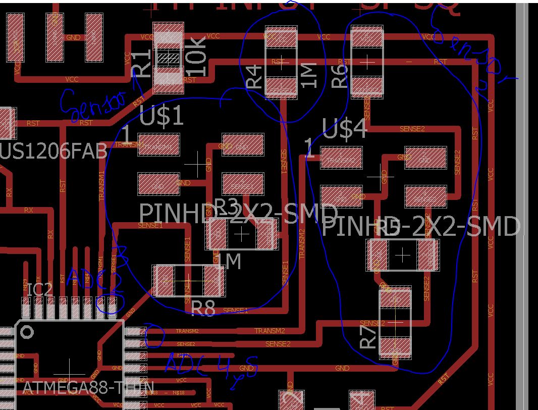
placing the components and erasing the output connections.
Placing the components of the sensor is complicated, there are many pins in little space, not to cross the connections I add a jumper.
I have to add a jumper.
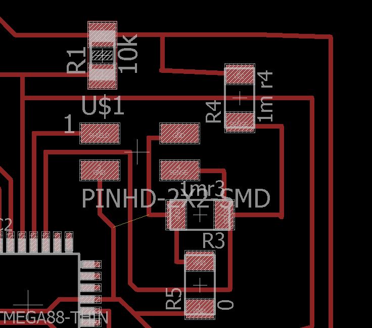
drawing traces.
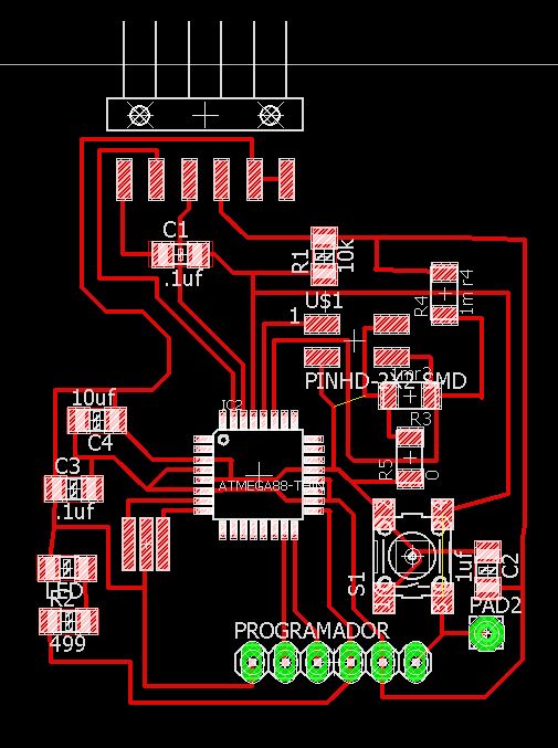
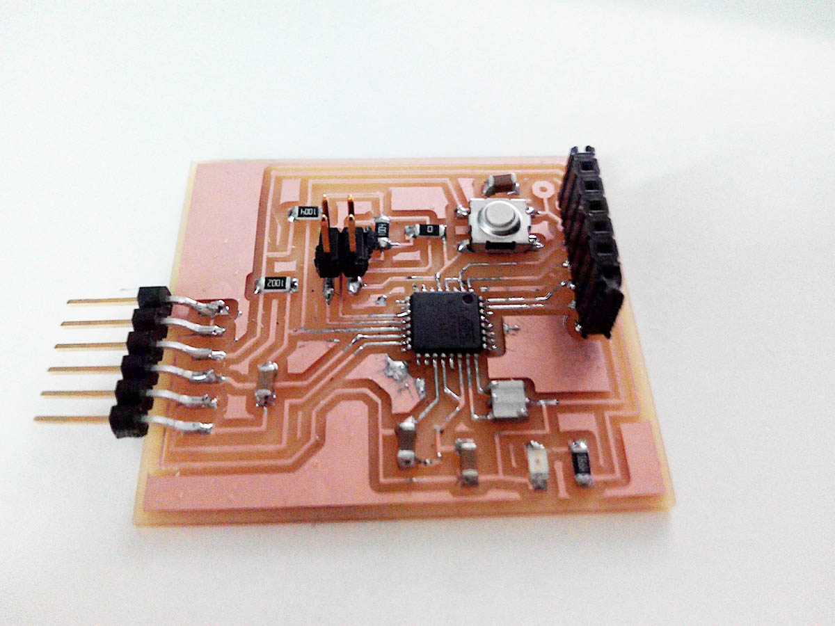
Input board.
This is the board that I will fresaré for this assignment we will name it as board1, you can see how it works in these two videos.
My first Schematic and the problem.
my first fail design.
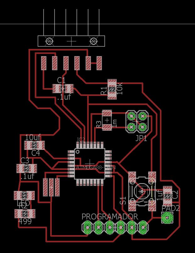
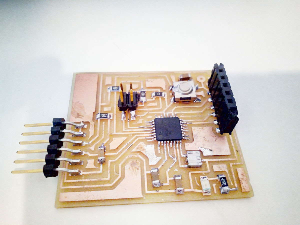
Input Board for my Final Project:
This piece is a board that I made in the assignment of networking based on the design of input, we will call it boardf2
Why do I do another board for final project? because I want to be able to communicate in serie with the output and send the information.
Then I made another board, in this case I made the sensor of my final project, based on the input plate, I made another board in this case with the possibility to connect 2 capacitive sensors and a serial connection to send and receive data.
I add another space for the sensor, which has to be connected to the nearby pins, the function of having 2 sensors of these could be calculate in addition to a large weight calculate the speed between two sensors separated a distance.
Schematic
On the other side I also add the pin for serial communication.
New sensors
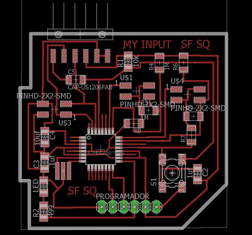
Final Input board
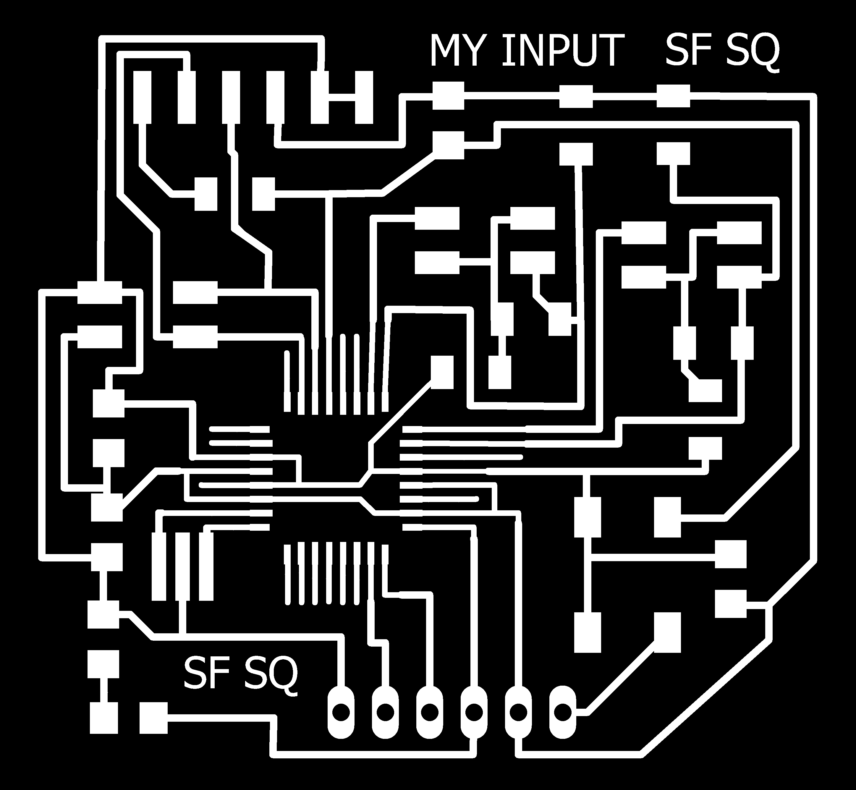
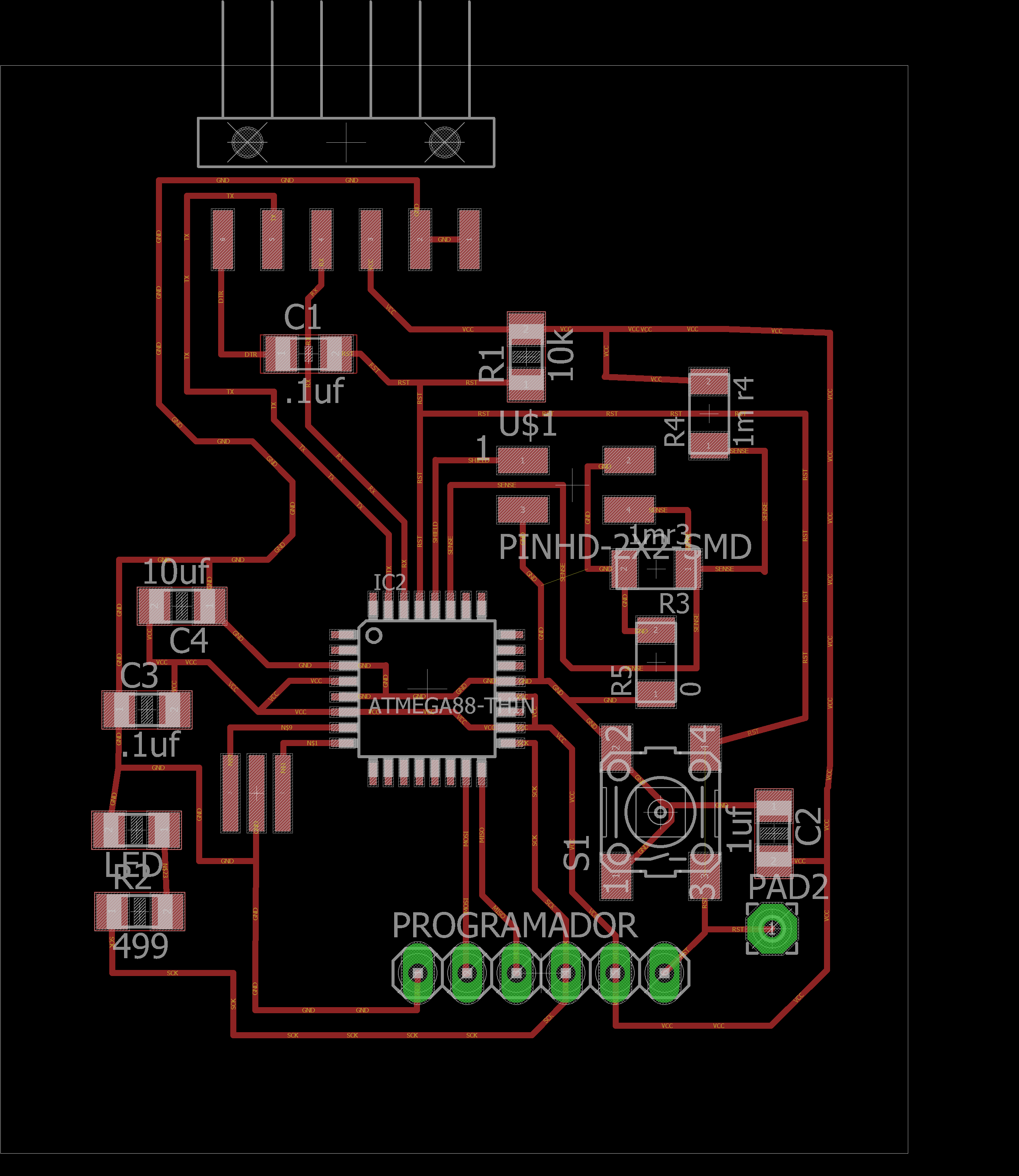
traces

pads
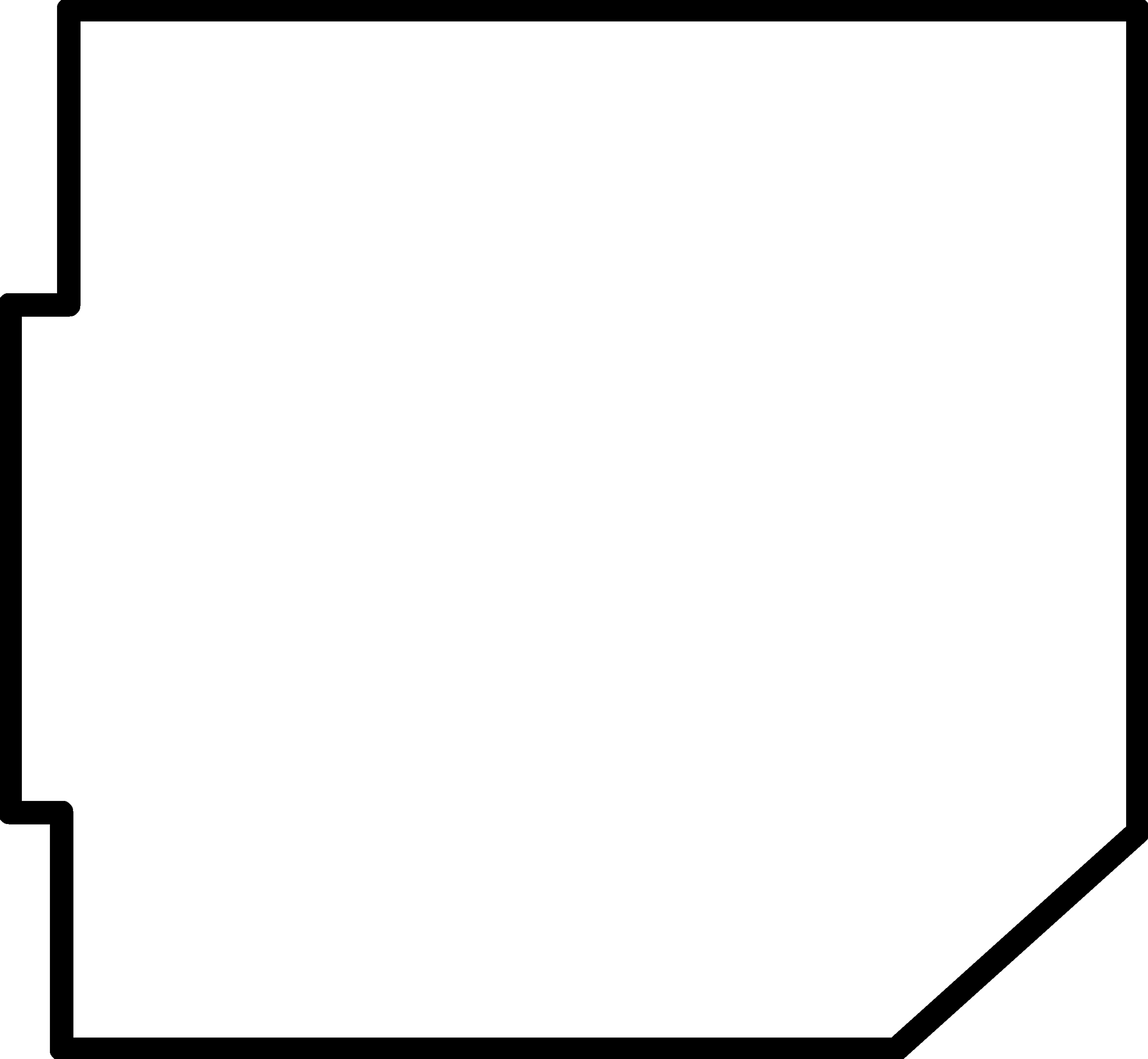
Frame
--- 2. Produce it. ---
we will continue with the explanation of how I made the first board.
When I already had the board designed, I exported the drawings from eagle and separated the files in Traces (1/64), Pads, and frame (1/64).
To mill in this order.
The PNG image of Pads and Frame I get it from photoshop by modifying the original traces.
My input design.
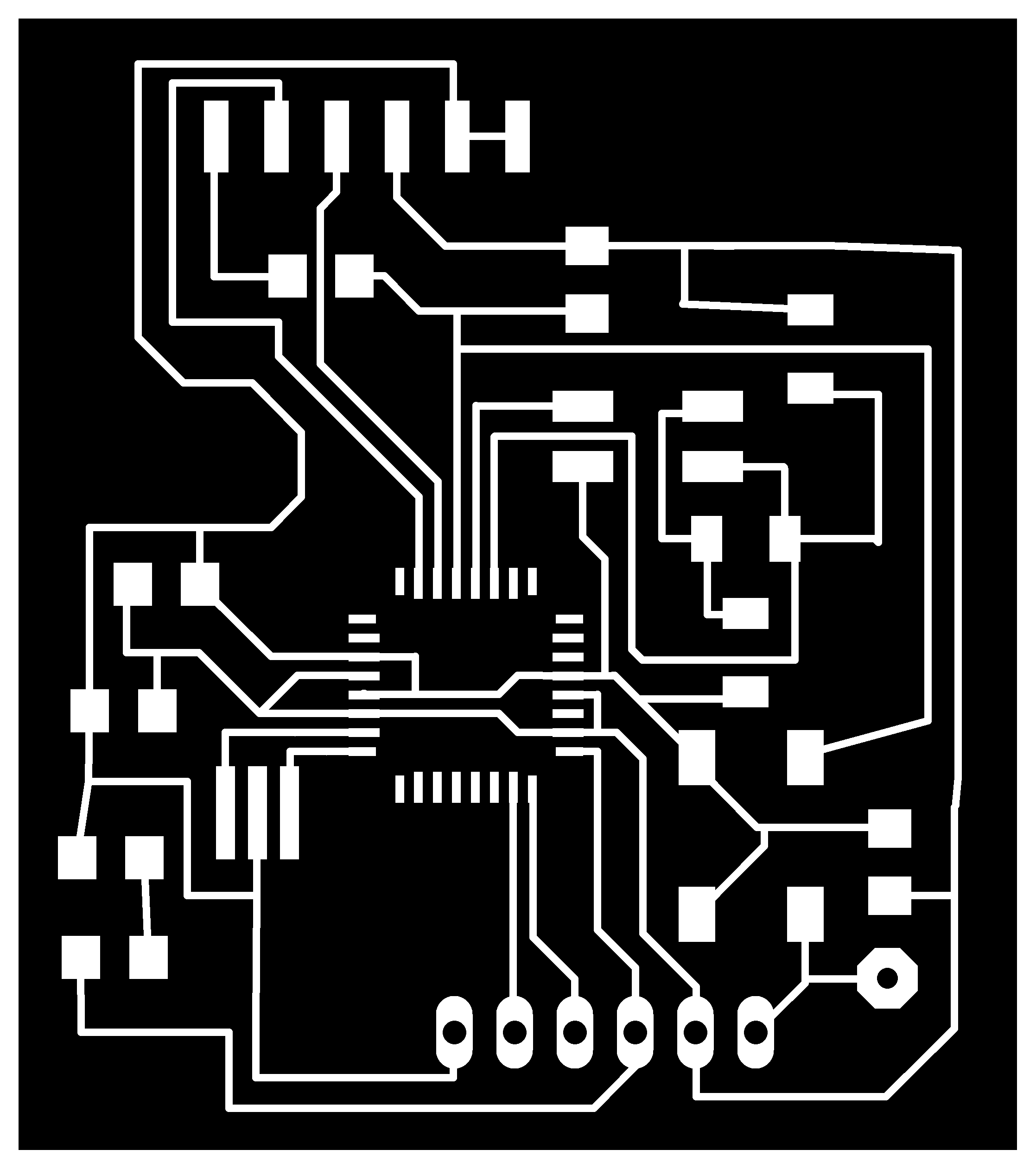
traces.

Pads.

Frame.
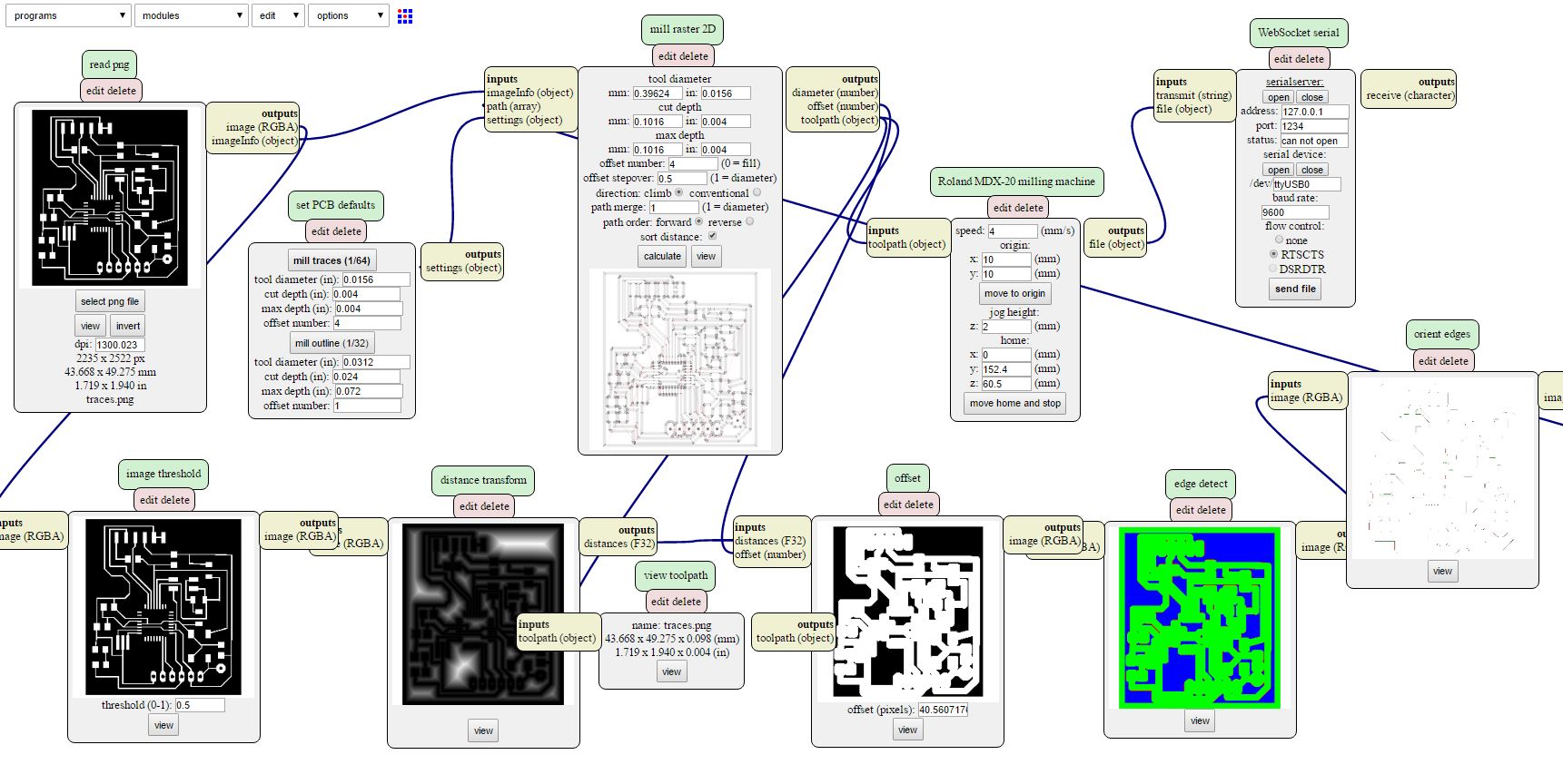
The way to prepare the file for milling in the mdx-20 is similar to other assignments, using mods, choosing the type of cutter, number of offsets, calculating and sending each file separately.
Calculating and milling the board.
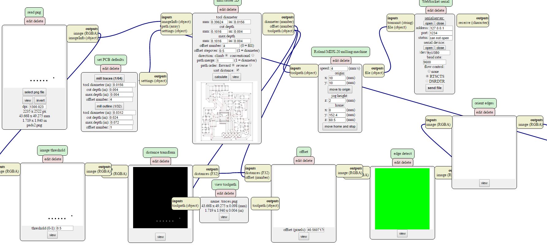
Calculating and milling the pads.
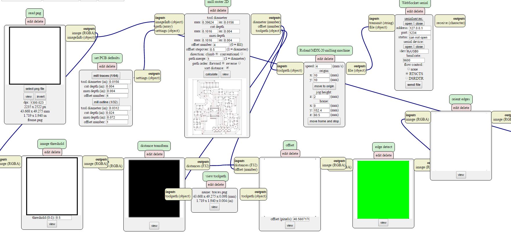
Calculating and milling the frame.
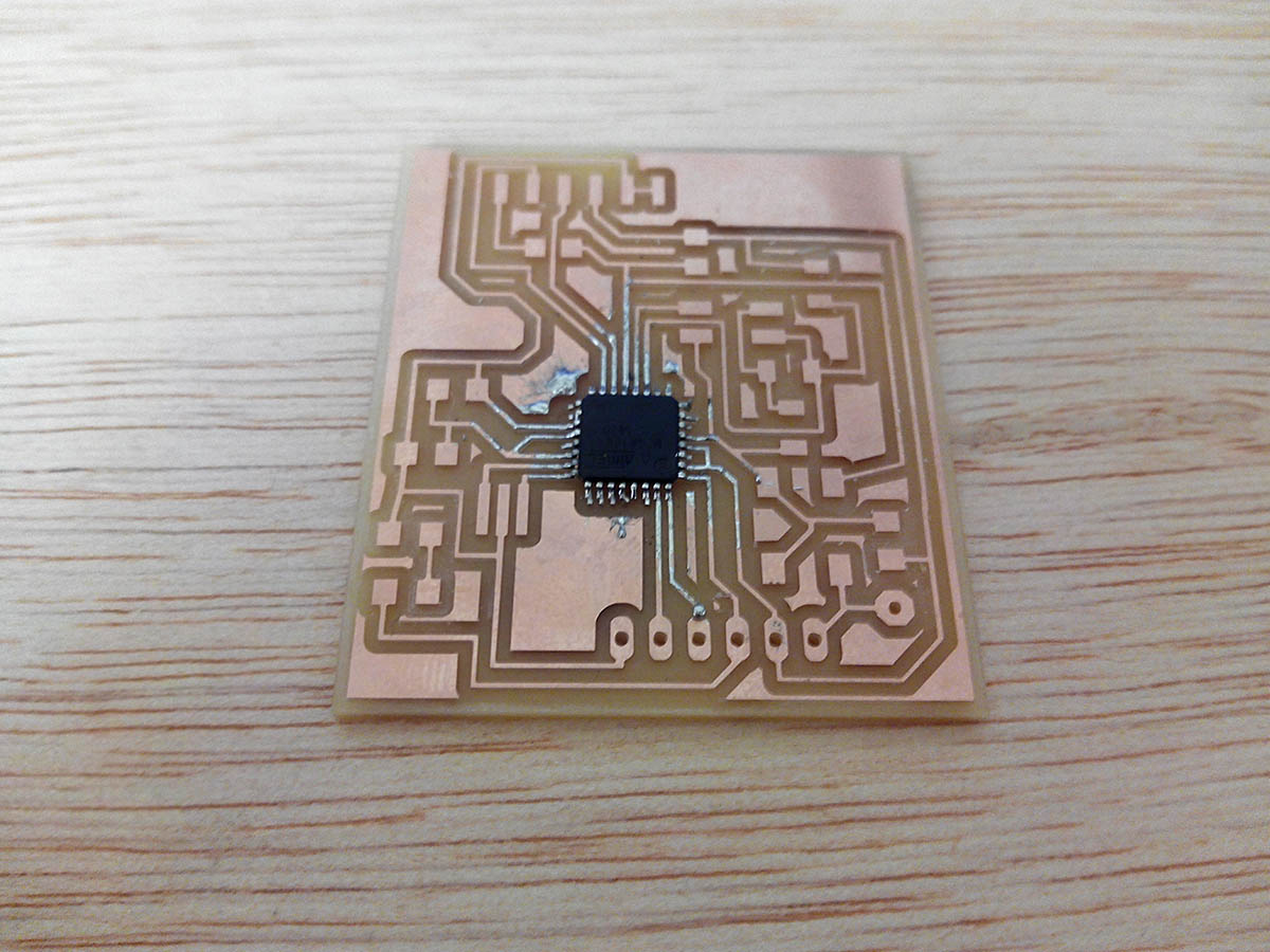
My board.
Problems:
The measurements of the traces are too small at some point, I was wrong to define the design rules, in addition some traces of the microcontroller did not appear.
In the final design of the final project board I have solved the minimum measures and values recommended for traces.
--- 3. List of components. ---
This is the list of components that I need there is a function in Eagle that prints all the components added at the design.
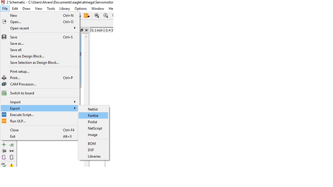
You can print a list of the components of your file in Eagle export part list.
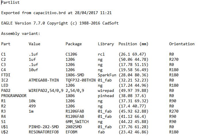
List of all components.
--- 4. Solder all the components and test it. ---
I had problems soldering the microcontroller, the size is very small and when I cut the board some pin that was not connected disappeared.
I started soldering the components in order, first the microcontroller, then the smaller components and in the end the bigger components or connections.
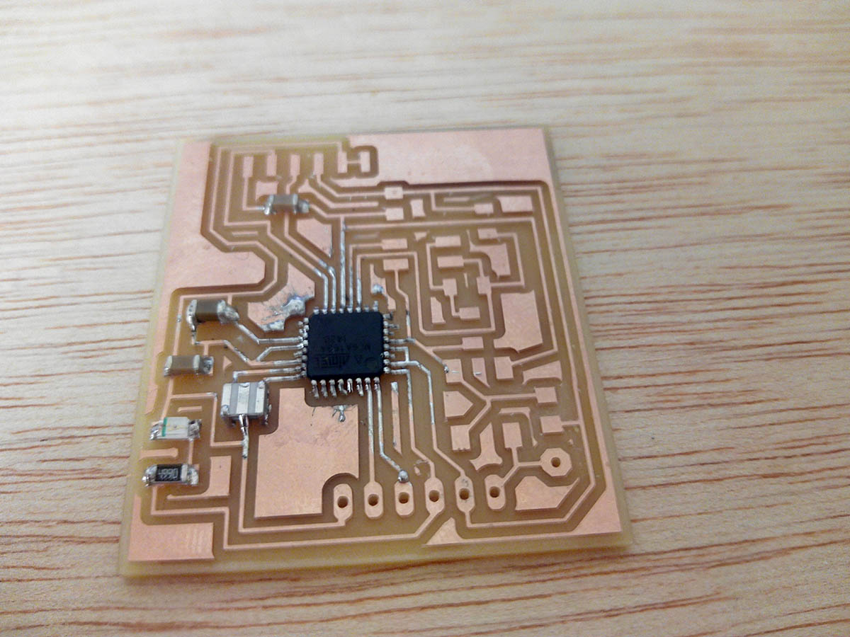
soldering components.
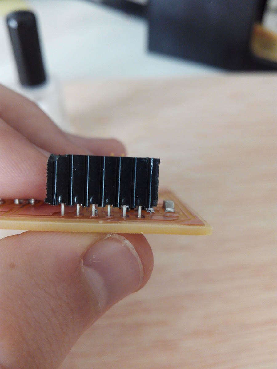
6 pin connection called ''programador'' I have to solder at this distance.
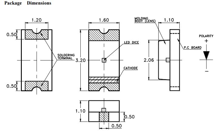
If I have any doubts about how to place a component in the datasheet there is useful information.
I had to search the datasheet of the led for know were is the ground.
Final board (ups the microcontroller its in the wrong way).
When I soldered the microcontroller I did it wrong I tried to fix it but when desoldering I lost pins and ended up breaking the microcontroller.
For this reason can not make the bootloader, because the chip is misplaced.
THE NEW BOARD :I had to make the board again, and solder all the components, apparently the chip did not work, I soldered the new chip.
Correct connections.
Now the next step is that the board be recognized by the computer and programmed with the fabisp.

The windows device manager recognizes the board.
Then I programmed with the fabisp the new board doing the bootloader.
Here is an image of how to program the board, going from a 3x2 pin header to a 6x1
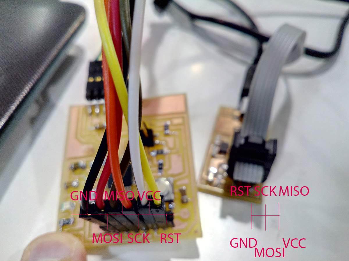
Correct connections.
I got everything correct and I could do the bootloader
Next step is to programming something simple.
--- 5.Program something simple with the board. ---
the first step to see if the board is properly is programmed so that the LED lights up, the LED is on pin 17 of atmega 168 corresponding to the SCK.
In arduino this pin corresponds to pin 13.
/*
  Blink
  Turns on an LED on for one second, then off for one second, repeatedly.

  modified 8 May 2014
  by Scott Fitzgerald

  modified 2 Sep 2016
  by Arturo Guadalupi

  modified 8 Sep 2016
  by Colby Newman
*/


// the setup function runs once when you press reset or power the board
void setup() {
  // initialize digital pin LED_BUILTIN as an output.
  pinMode(13, OUTPUT);
}

// the loop function runs over and over again forever
void loop() {
  digitalWrite(13, HIGH);   // turn the LED on (HIGH is the voltage level)
  delay(1000);                       // wait for a second
  digitalWrite(13, LOW);    // turn the LED off by making the voltage LOW
  delay(1000);                       // wait for a second
}
And this is the result:
Yes input board it is working!!.
Question3:How did I make the sensor ???
Making the sensor rubber:
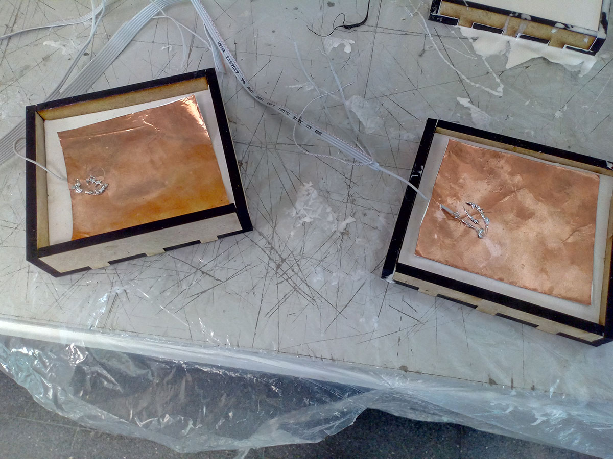
I will fabricate a sensor with two copper plates and an element in between so that the voltage difference will vary when they are closer together and when they are more apart.
In this way what I put between the copper plates to be elastic will make my sensor more sensitive or less depending on what deformed the material and other factors such as conductivity.
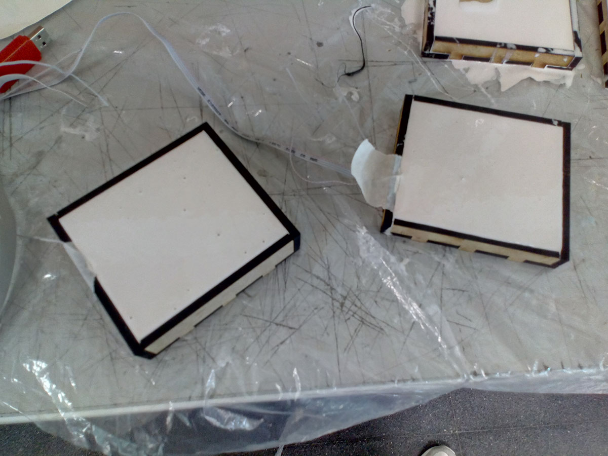
To make the rubber of the sensor, I will make some molds that are boxes, 5mm 10mm and 20mm high.
To pour the silastic 3481 and get rubber sheets.

Rubber used in the sensor covering.
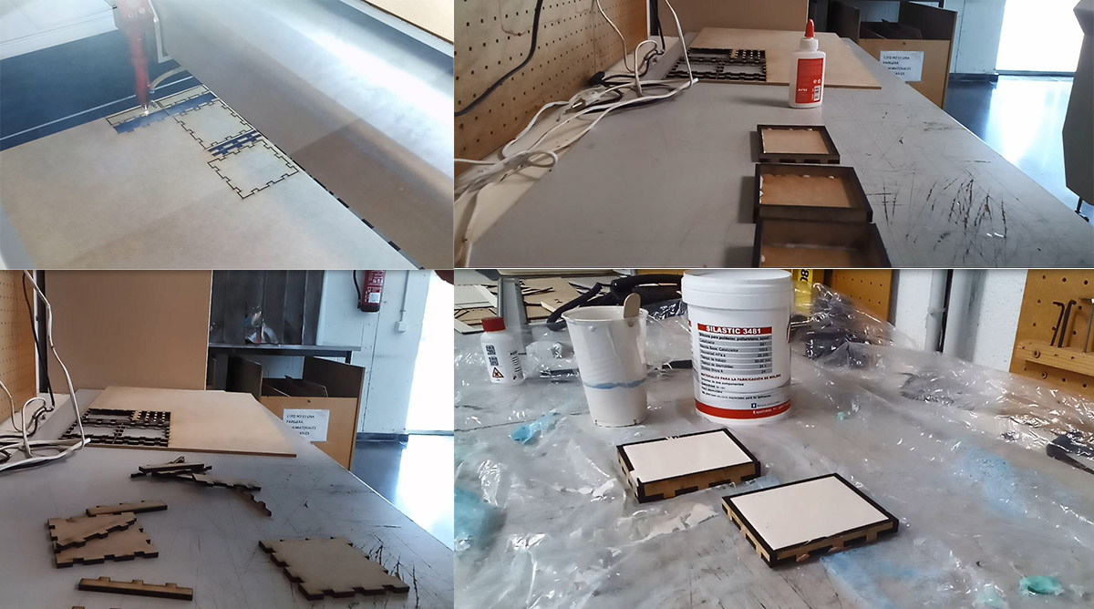
cutting,glue and making boxes and the rubber .
the sensor works as follows, being a potential difference by programming the current that reaches the pins of the microcontroller to which the sensors are connected, if the difference in voltage between the two is very large the result of the programming will be a large number, if the two plates are close together the voltage differential will be small and will tend to 0.
The pressure that is exerted will vary the number that is read in the serial monitor in the programming.
We have on the one hand the receiver and on the other the transmitter, we will place the RX and TX in the way Neil explains in the example helloTxRx.
You can see how Neil explains the helloTxRx and how to make a capacitive pressure sensor in the next video.
In this video how to place the sensor, what other possibilities can be made with this type of sensors and how the dielectrics sensors work. MIN 51:00
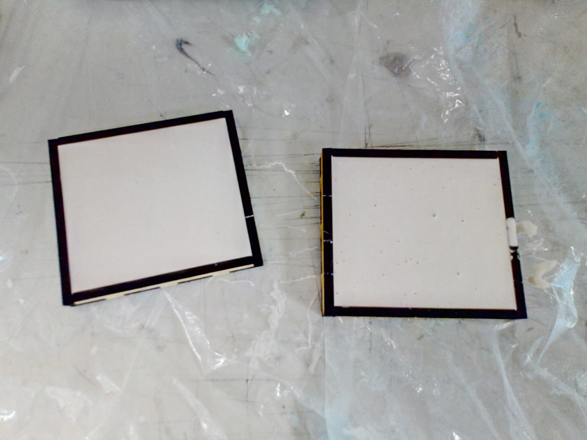
I have made two sensors to be able to calibrate better, one of the sensors will have less quantity than another and will be by test when you see which is better and more resistant to do the final project.
The tx goes to the copper plate while the rx returns from the vcc divider and the Gnd and returns to the pin.
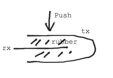
The receiver is placed inside the rubber and the transmitter around it wrapping.
Here the result.
drying the rubber
making the base of the mold
covering the cupper
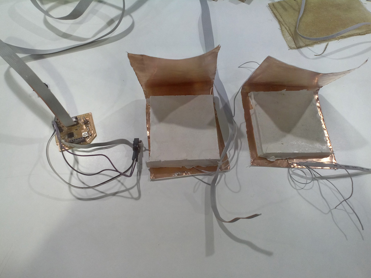
sensors finished
So that there are no movements and the copper is fixed to the rubber will use tape
--- 6.Program a pressure sensor. ---
Question3:How do I have to configure the sensor to be able to read what you want ???
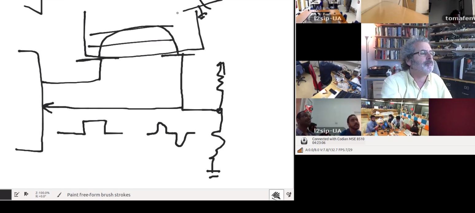
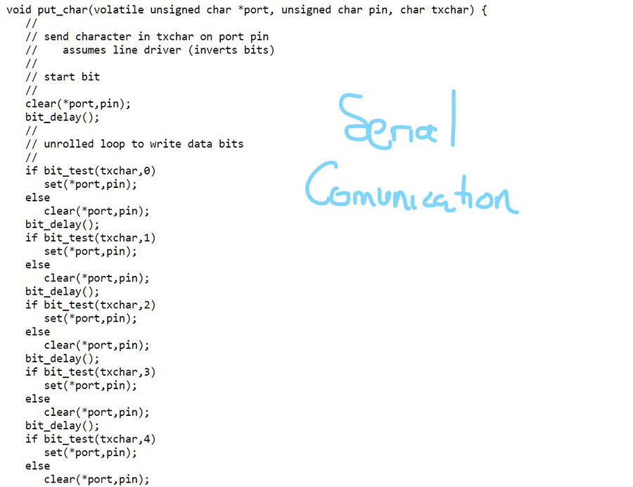
For programming I relied on this program of Neil the hello Tx Rx written in c, through the datasheet I was able to know what I was doing in his program and to be able to do a program in arduino that did the same custom function.
This is Neil's program, and these are the screenshots to understand it.
The program of the input what it does is prescalar the clock of the pins of the microcontroller that go to the sensor, it measures the value of the tension and it keeps doing the same with the information that arrives to him of the receiver.
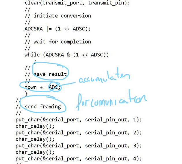
Then it makes the difference of the tension between the two and writes its value in the monitor in series.
For the final program. Here for the input I put an if variable, if the value is higher than a value that determined by putting 80kg (for the test was 47,000) on the sensor write the char "5" after the value read.
if the value of the reading does not reach that value or write nothing or write an 8.
These values 5 and 8 will be those that the output reads to activate in one position or another.
The next step is to pay attention in neil programming in .C try to convert the programming of hello txrx in a sketch written by me in arduino with the same functions, to be able to control the programming.
Later using the references of arduino and understanding his program I have done the same program in arduino because I handle it better, and this way to modify it as I want.I have selected some screenshots in which I am learning what steps neil performs in their programming in c.
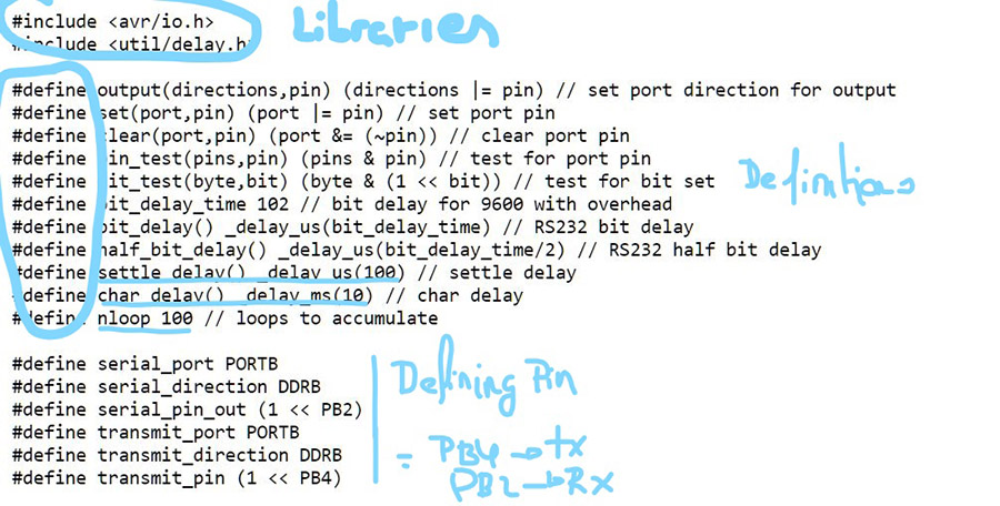
in the first image is adding some libraries for c, and defining the vocabulary and variables, for example the call settle delay to a delay with value 100
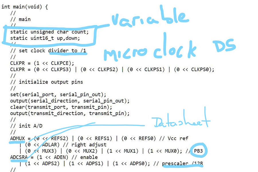
in this screenshot is showing how to select the PB3 pin from c, and change the prescaler to 128.
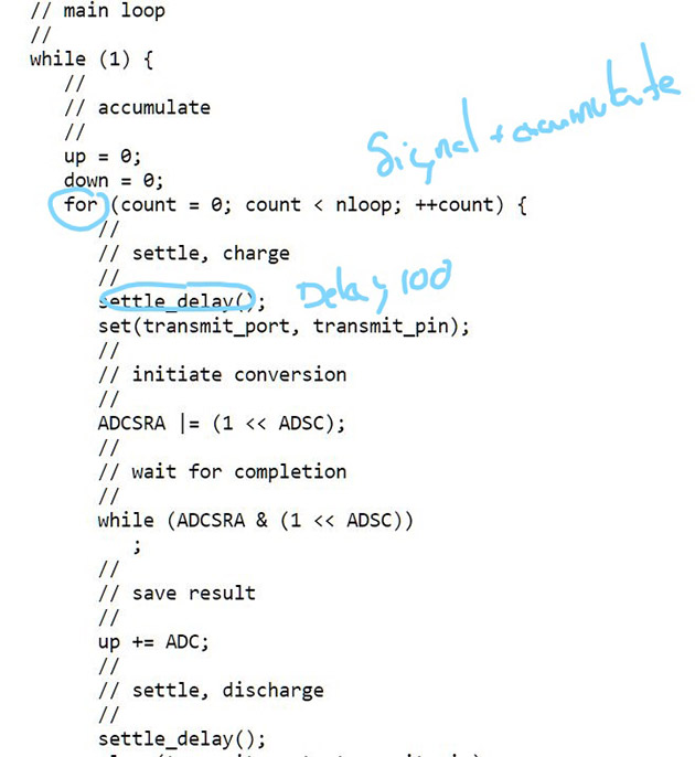
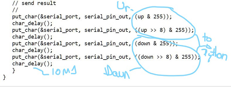
In this other accumulate values of up and down, in the reading and show the difference of the values between one and the other, with a delay of 100.
To understand and be able to change the neil program of the capacitive sensor I need among other things to understand well the datasheet of the microcontroller atmega 168.
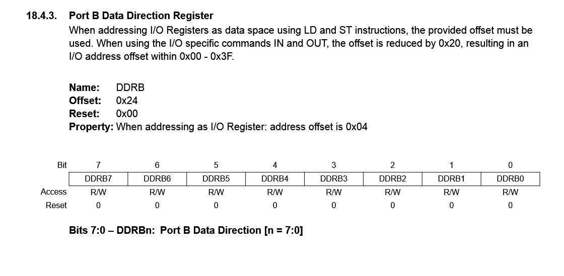
defining pin
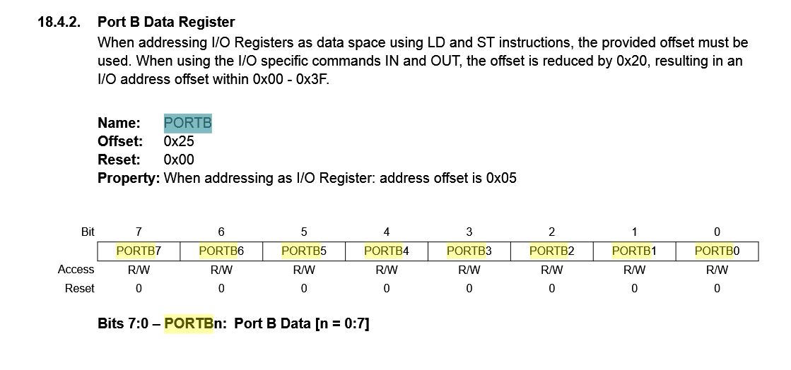
defining portB
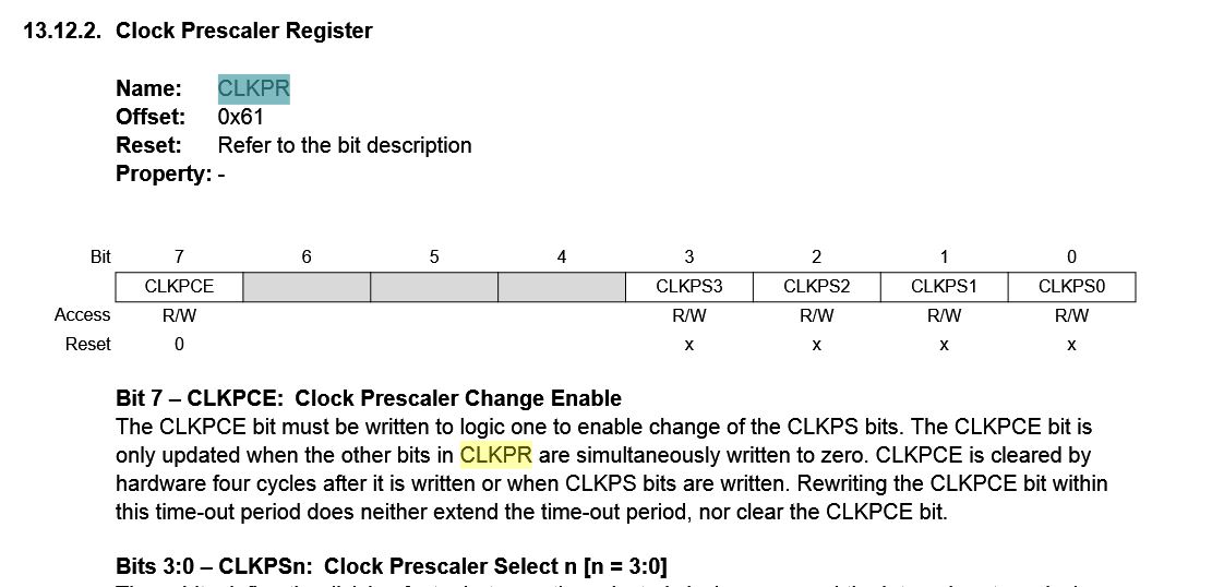
making clock divider to /1
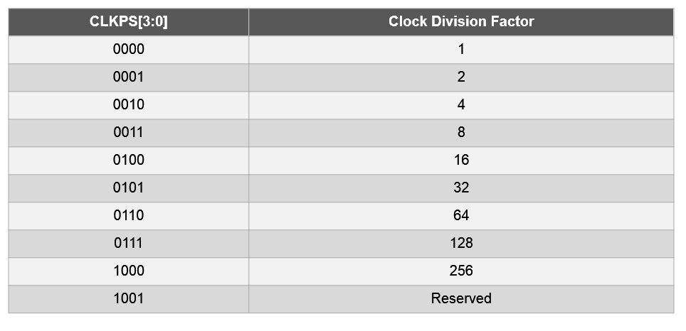
0000
Preescaler 128
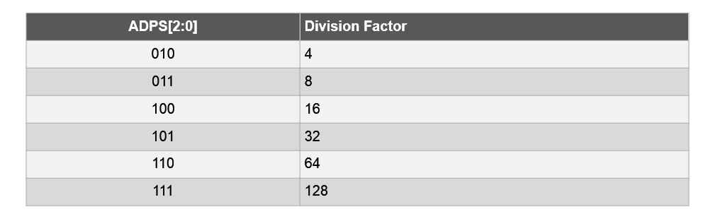
111
This is the final code I have created, there have been many more attempts that have not worked correctly well, however I think I have managed to read the pressure sensor correctly and program it in arduino.
/* Programmed by Alvarolaroja 23/05/2017 traduced from Neil G. in C Hello TxRx */
#include <avr/io.h>
#include <util/delay.h>
static uint16_t up,down;
static uint16_t arriba, abajo;
void setup() {
// pinMode(A5, OUTPUT);
DDRC |= (1 << PC5);
PORTC &= (~(1 << PC5));
Serial.begin(9600);
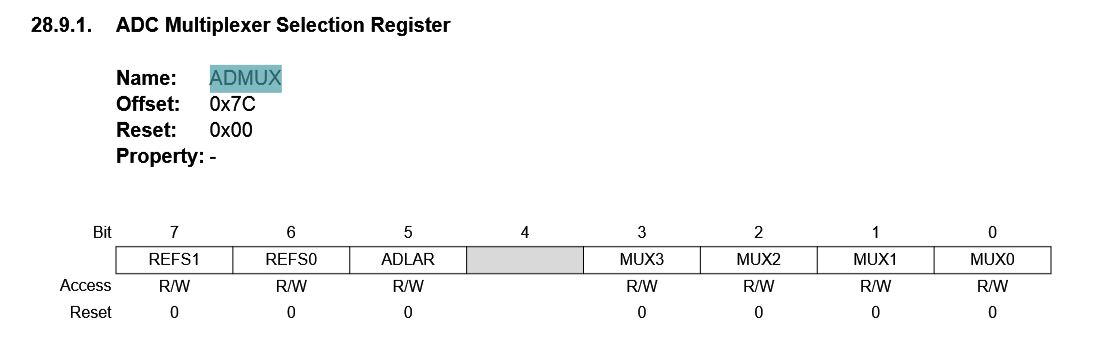
ADMUX = (0 << REFS1) | (0 << REFS0) | (0 << ADLAR) | (0 << MUX3) | (1 << MUX2) | (0 << MUX1) | (0 << MUX0);
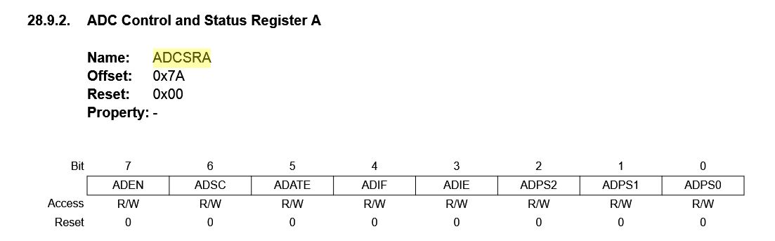
ADCSRA = (1 << ADEN) | (1 << ADPS2) | (1 << ADPS1) | (1 << ADPS0);
}
void loop() {
up = 0;
down = 0;
for (int count = 0; count < 100; ++count) {
_delay_us(100);
PORTC |= (1 << PC5);
//digitalWrite(A5,1);
//arriba = analogRead(A4);
ADCSRA |= (1 << ADSC);
while (ADCSRA & (1 << ADSC)){
;}
//up += arriba;
up += ADC;
//mySerial.println(up);
_delay_us(100);
PORTC &= (~(1 << PC5));
//digitalWrite(A5,0);
//abajo = analogRead(A4);
ADCSRA |= (1 << ADSC);
while (ADCSRA & (1 << ADSC)){
;}
down += ADC;
//down += abajo;
}
Serial.println(up-down);
_delay_ms(10);
/*
Serial.write(1);
_delay_ms(10);
Serial.write(2);
_delay_ms(10);
Serial.write(3);
_delay_ms(10);
Serial.write(4);
Serial.write((up & 255));
_delay_ms(10);
Serial.write(((up >> 8) & 255));
_delay_ms(10);
Serial.write((down & 255));
_delay_ms(10);
Serial.write(((down >> 8) & 255));
_delay_ms(10);*/
}
With the board sending data of the voltage difference between the two plates, values approaching 0 are continuously displayed when the two copper plates are together and increase nearing the maximum value when they are separated.In the following video you can see how this programming works:
FINAL VIDEO:
In the following video I show how the sensor works, collecting the data that I get from the serial and transforming them into a graph in real time. Processing is used to display the proximity values of the cupper plates of my sensor.
Here you can see the values that the sensor sends, in with normal proximity the sensor sends values close to 43,000 when the sensor is tight the plates are closer and rise up to 49,000 if strong presses can rise to 50,000 -51,000 if you you climb above the sensor you can reach 52,000, for a car the program would be if> 53,000.
I remember that the sensor gives different values for the distance that is of the plate and the type of ground in which it is.
note: these last two videos are made with the boardf2 made with networking time after the assignment of the week 13, as you can see in video 1 and 2 the board 1 communicates correctly and does the same function as boardf2 but can not communicate in series with the servomotor, you have the code in the final project page.
In this other program the board no longer sends values if not only 5 or 8 so that the board of the output reads better, when an 8 comes out by the serial monitor the servomotor is activated.
FILES:
Step response Alvaro
board
traces
Pads
Frame
Arduino inputsensor