Assignments:
- Make something big (on a CNC machine)..
--- WORKFLOW ---
1. design the test tolerance and test the joints2. Milling your test file
3. Correct the mistakes
4. Design something big (an Arcade Bartop machine)
5. Design the joints and make it in 3D.
6. export to dxf.
7. Adjusting the intersections and presets of the milling.
8. Send to Shopbot
9. Upload the material and ignite the machine and setting up the mill and run the cutting.
10. Assemble and sand the pieces.
I am going to make a tolerance test to know tolerances between joints, different ways of intersecting and practice cut down and hidden joints.
I have designed two pieces that come together with different tolerances to know the Kerf that I can leave.
designing the test 1
test 1 tolerances and different joints, hidden and crossing.
The result
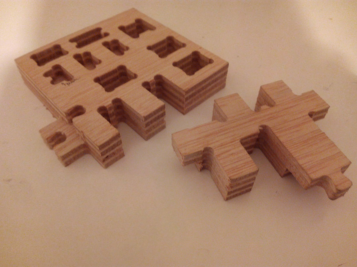
These are the possibilities of union between these two pieces.
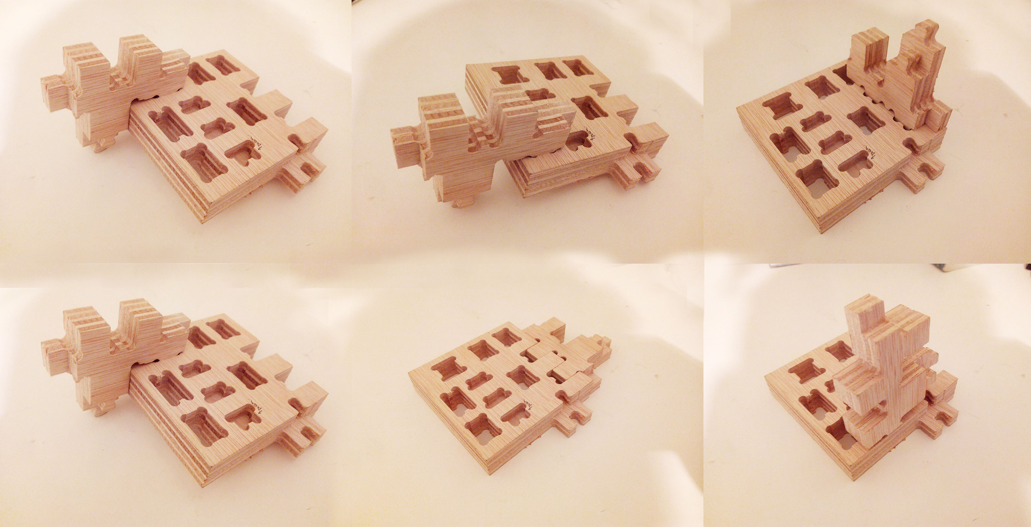
The result
From here we have seen the joints that interest us most.
In this case the hidden joint that I like for my arcade machine is this, which measures exactly 15.50mm by 10.50 and with a 10mm tolerance of 0.5mm.
--- Designing the arcade bartop machine:---
First I got from this direction the plans of how to make a diy arcade machine in wood.
Because most of the measures are studied and are of a certain size.
These plans are orientative and to make a machine by hand.
My first step is to convert this machine to be handmade in one made by cnc.
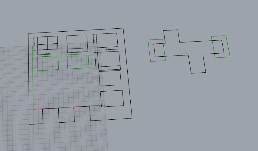
I started drawing the pieces, and then I added the timely joints already studied.

Plans for a bartop arcade machine, handmade.
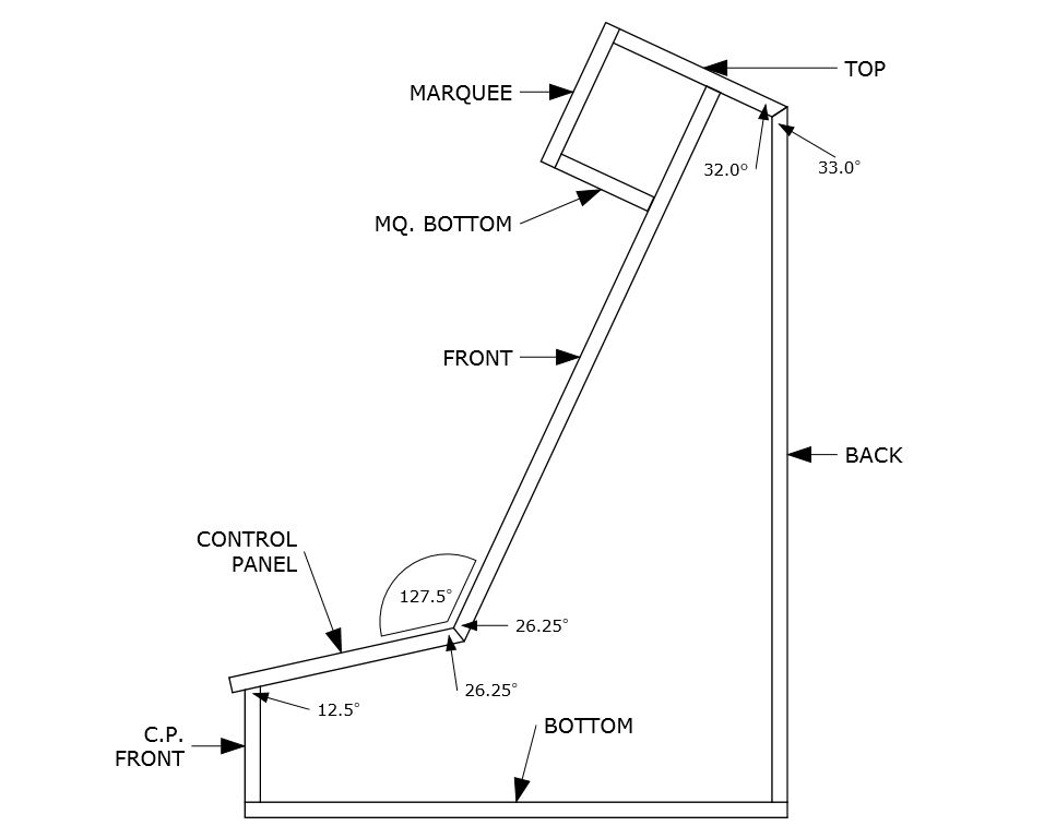
Section and angles.
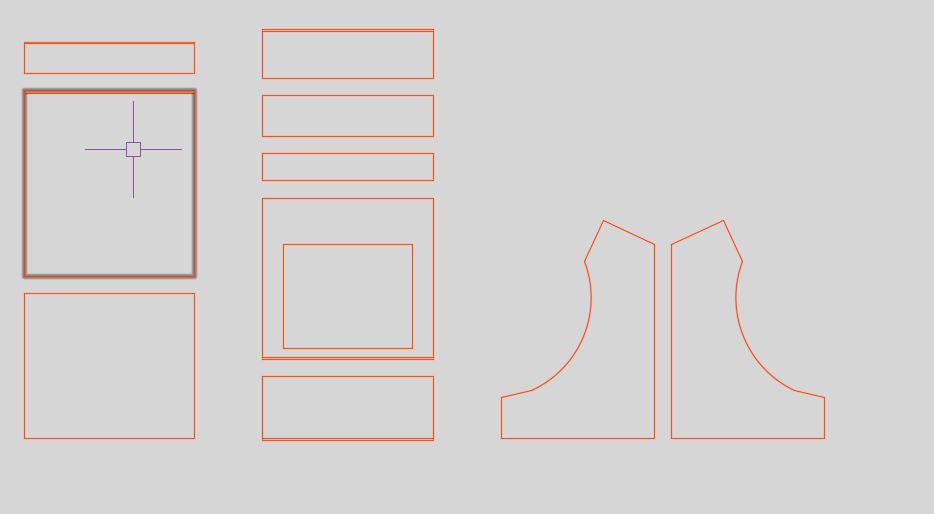
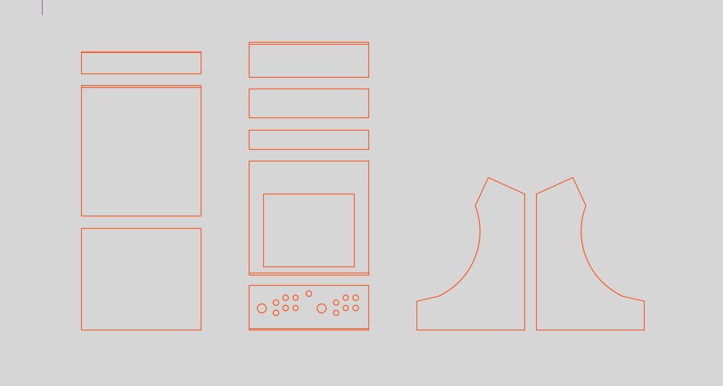
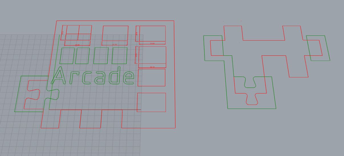
adding the control panel.
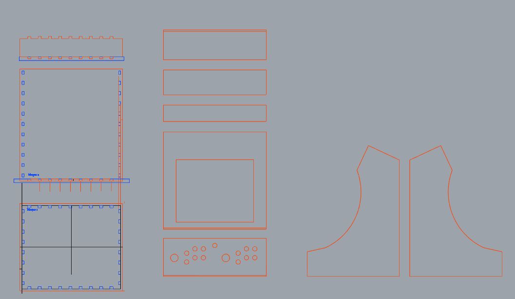
drawing the joints.
and the cutdowns in all panels.
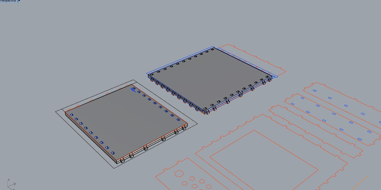
Making the 3d.
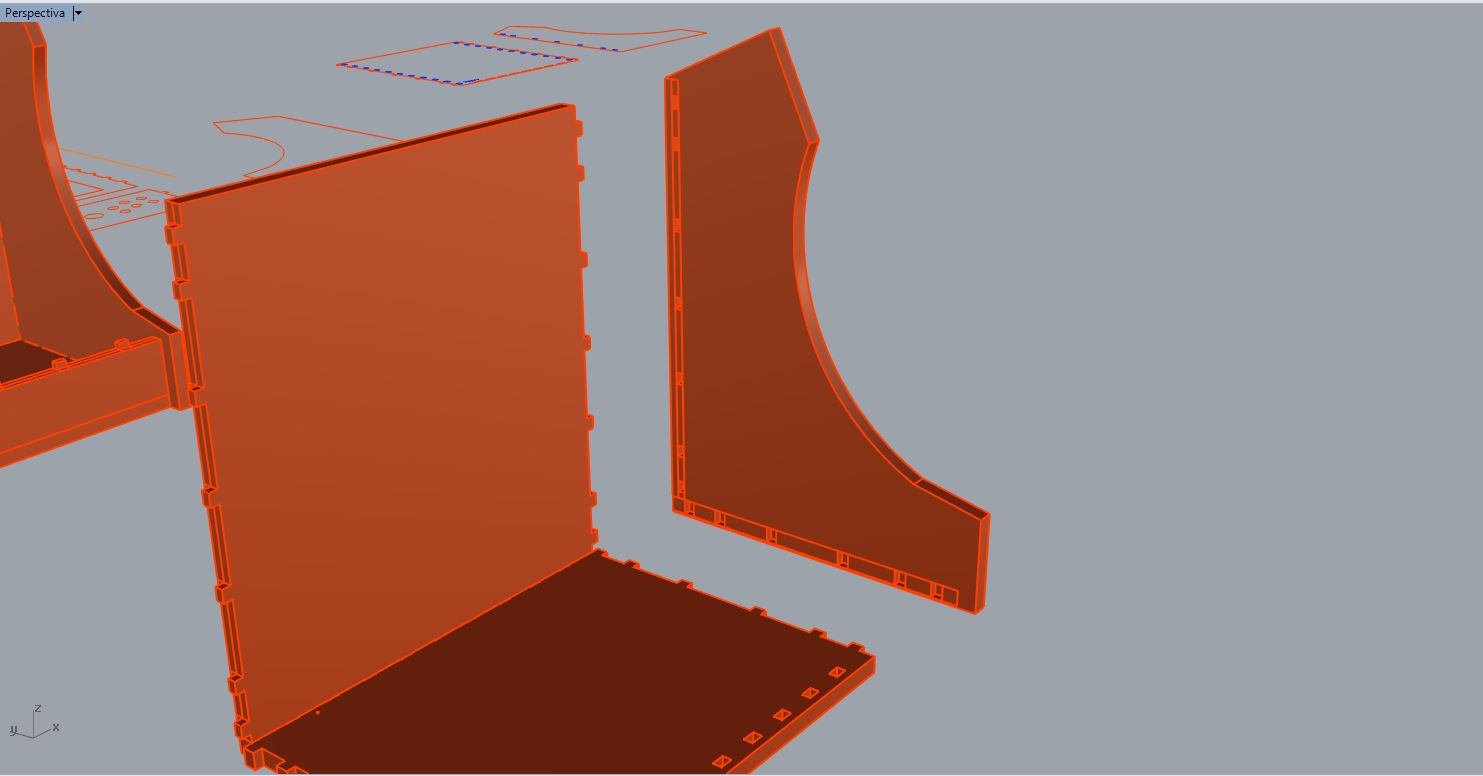
Lateral piece.
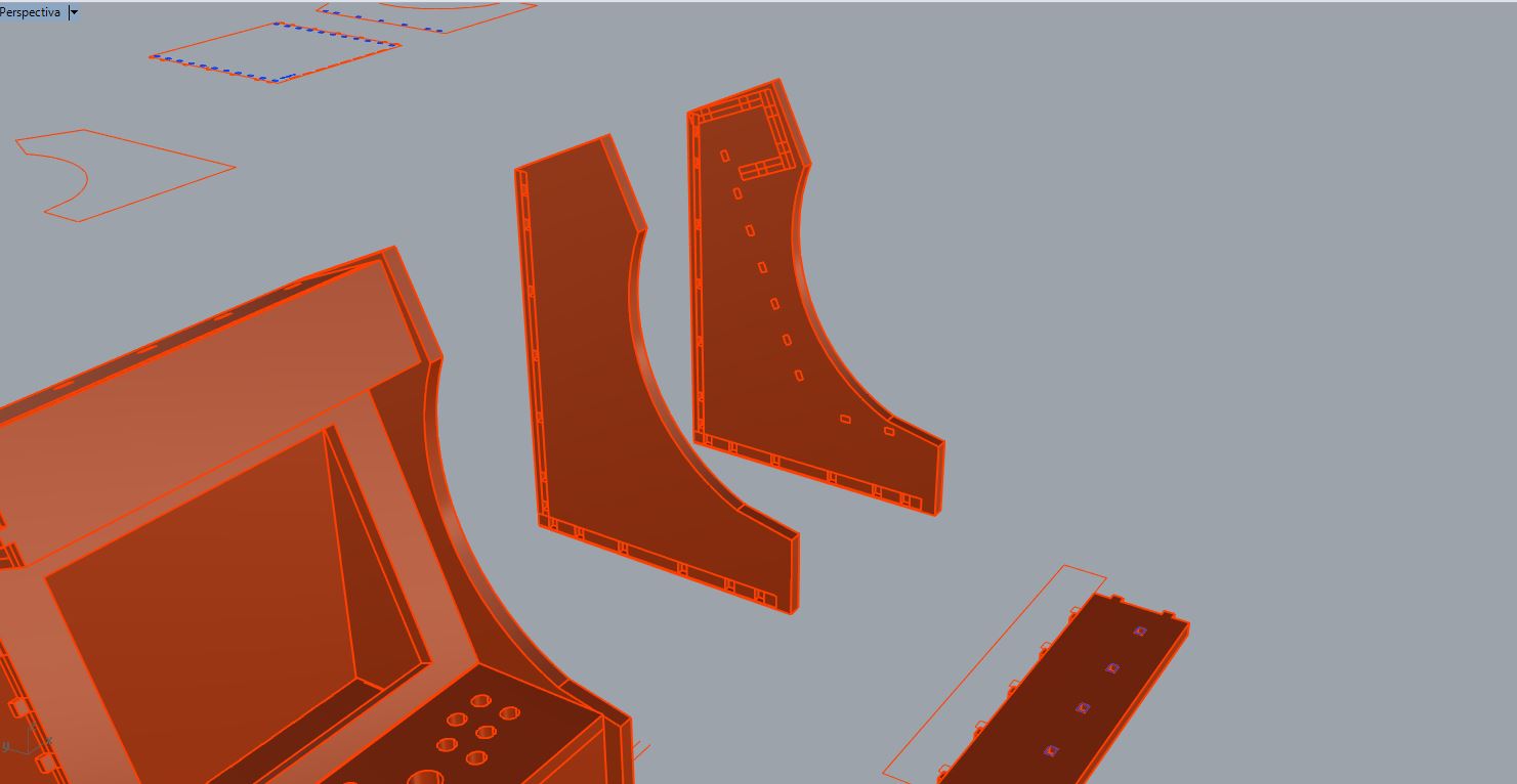
Getting the joints on the side by booleans.
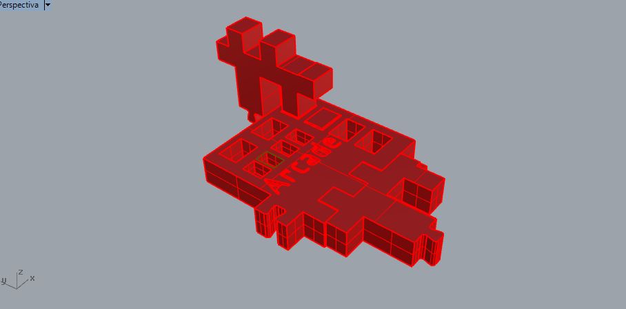
Once this was added, I turned it into a 3D model.
I had to repeat the process several times since I made mistakes sometimes, and redo the changes in 3D.
Not easy because some pieces have to be cut upside down.
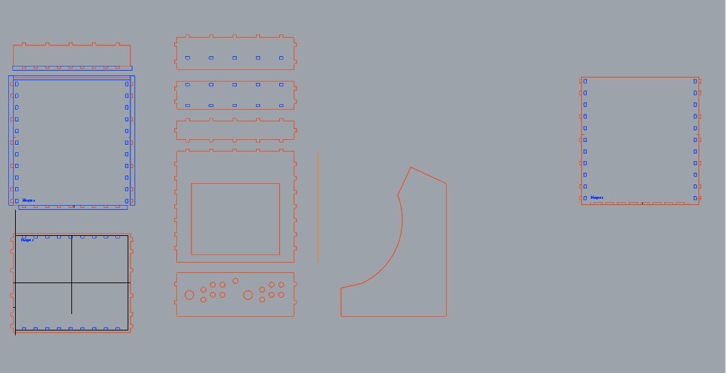
Detail of joints, the lateral pieces are made with boolean,and made to 2D
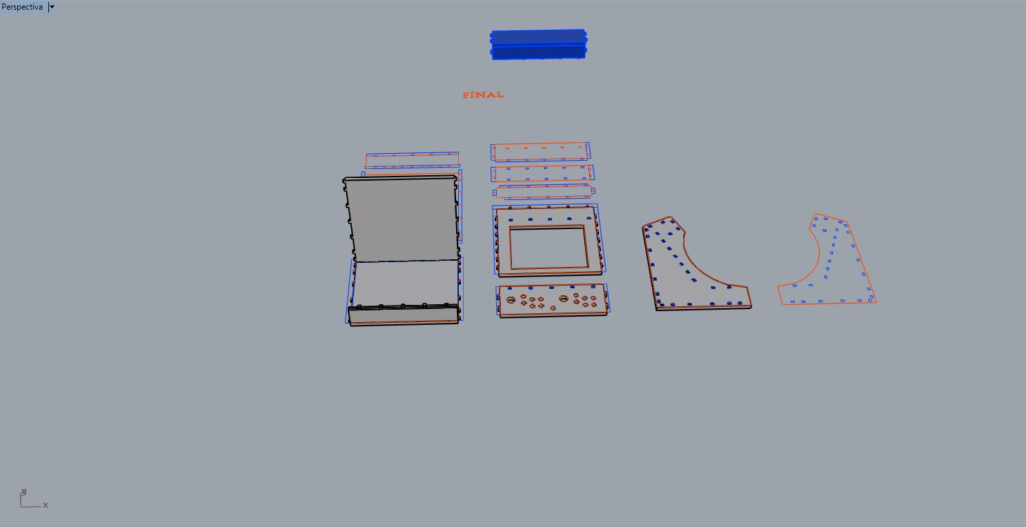
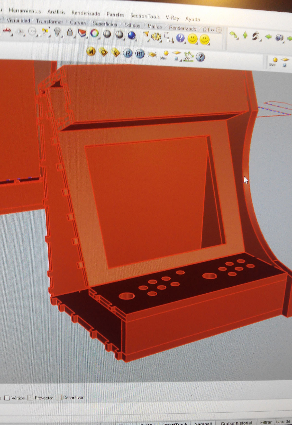
I finally got my 3d model along with my blueprints to send them to the machine.
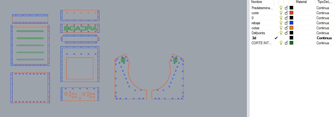
my design in 2D.
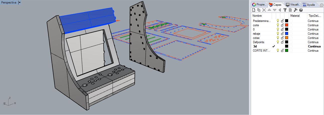
Final model in 3D.
--- Preparing cutting planes with Vcarve ---
The first thing we should choose in this program is the type of material, thickness and the relative zero in z and the origin position of the material.
It is very important that we measure well the thickness because if we put that it has more thickness can the CNC arm to lower too much and mills the table.
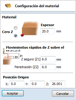
Material settings, thickness in milimeters, relative zero in z, origin position.
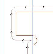
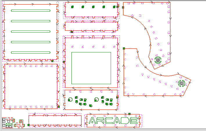
The intersections are very important, being the milling cutter a rotating cylinder can not perform in its cuts straight angles, the software gives you the possibility to make a splicing or cross the angle horizontal or diagonal.
In this case I chose the holes one side of the angle and I repeated this at all right angles of the design.
making intersections.

We put them at the intersections that are needed
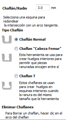
There are 3 types of intersections, "normal" fillet (rounds the inside of the angle), "dog-bone" fillet ( makes a diagonal fillet), "T-bone" fillet (the cutting tool perforate one side)
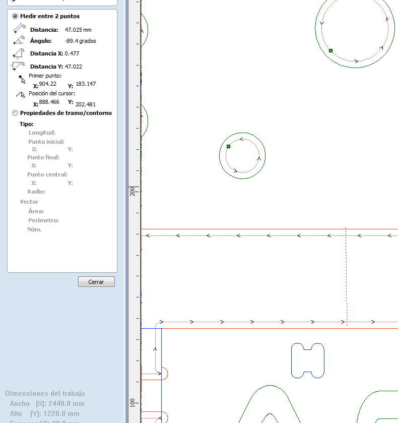
Then we place the cut drawings inside the plane and measure. there must always be a reasonable distance so that:
1. The milling cutter path is not overexposed in other parts of the drawing.
2. There is a safety margin of 1cm + 2 diameters of the milling cutter, so that the cnc arm and vibrations in the cut do not move the loose part, all parts must have a material margin to don't move during cutting.
We take measures at points that are too close.
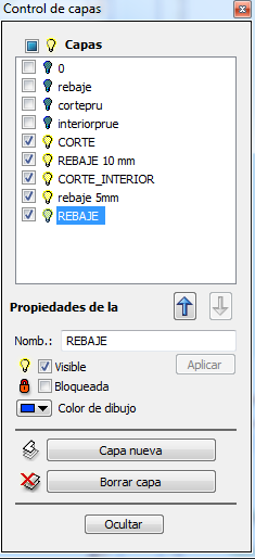
We place the planes importing the previous cut, this is the layer manager you can show or hide the imported layers and rename it.
I'm going back to showing the cut I made for the material test to adjust the new planes to that gap in the material. (I'm using the same table as the test)
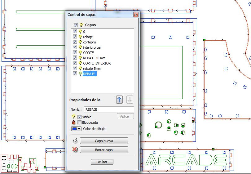
We place optimizing the space but without making mistakes, .
----Outer Cut:-----
in each cut layer I have to choose parameters such as the initial and final depth, the type of tool to use, if I want the tool to pass outside or inside, if I want it to rotate clockwise or counterclockwise.
if I want to make a ramp when start cutting, or if I want to put tabs and how many so that once the piece is cut it does not move.
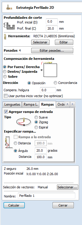
Parameters in english,initial and final depth, tool editor,inner or outer path, type of ramps, tabs, vector selection, name, calculate. .
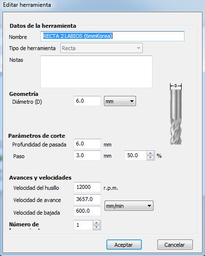
Choosing the cutter for each layer, tool editor, we have a we have a cutter of 6 mm diameter with a pitch of 50% this is 3mm per pas, rotation speed 12,000 rpm.
the tabs are small pieces of material that are not cut so that the piece does not move from its place while the cutting continues, you can choose the length and thickness of the tabs, and where we place them.
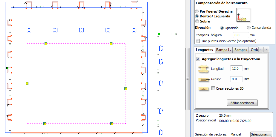
Tab editor, length, thickness and position of the tabs.
When we have chosen all the parameters of the outer cut makes an estimate of the time, and a summary of the chosen parameters, we can visualize the cut of this layer in 3D
Parameters in English, tool speed, starting position, safe z, estimated time, maximum depth..
We continue to choose the parameters of the other cutting types, in this case the cut-down
Depth 0 and final depth 10mm, select ramp input, cut counterclockwise, select the vectors of the route and calculate.
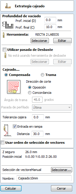
Cut-down parameters.
When all the cuts are defined we can preview the cut and the path of the cutter
the result
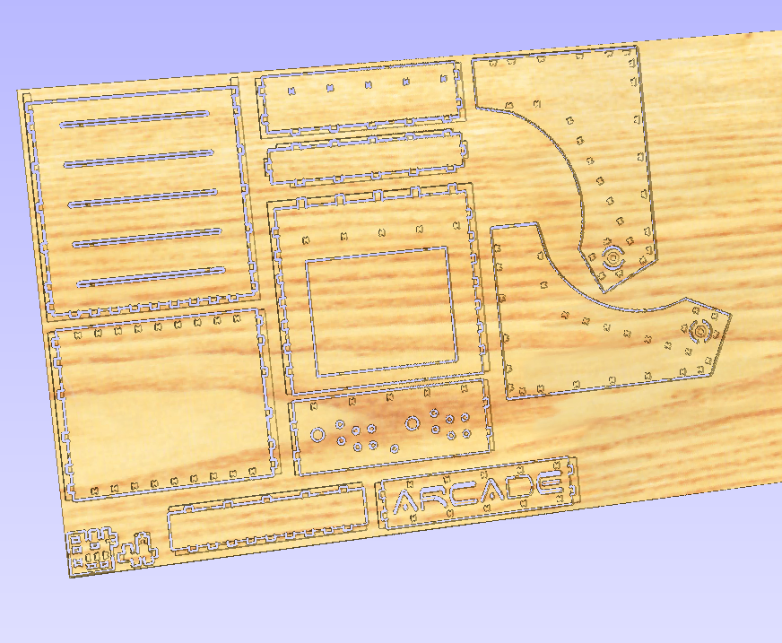
A preview of the cut.
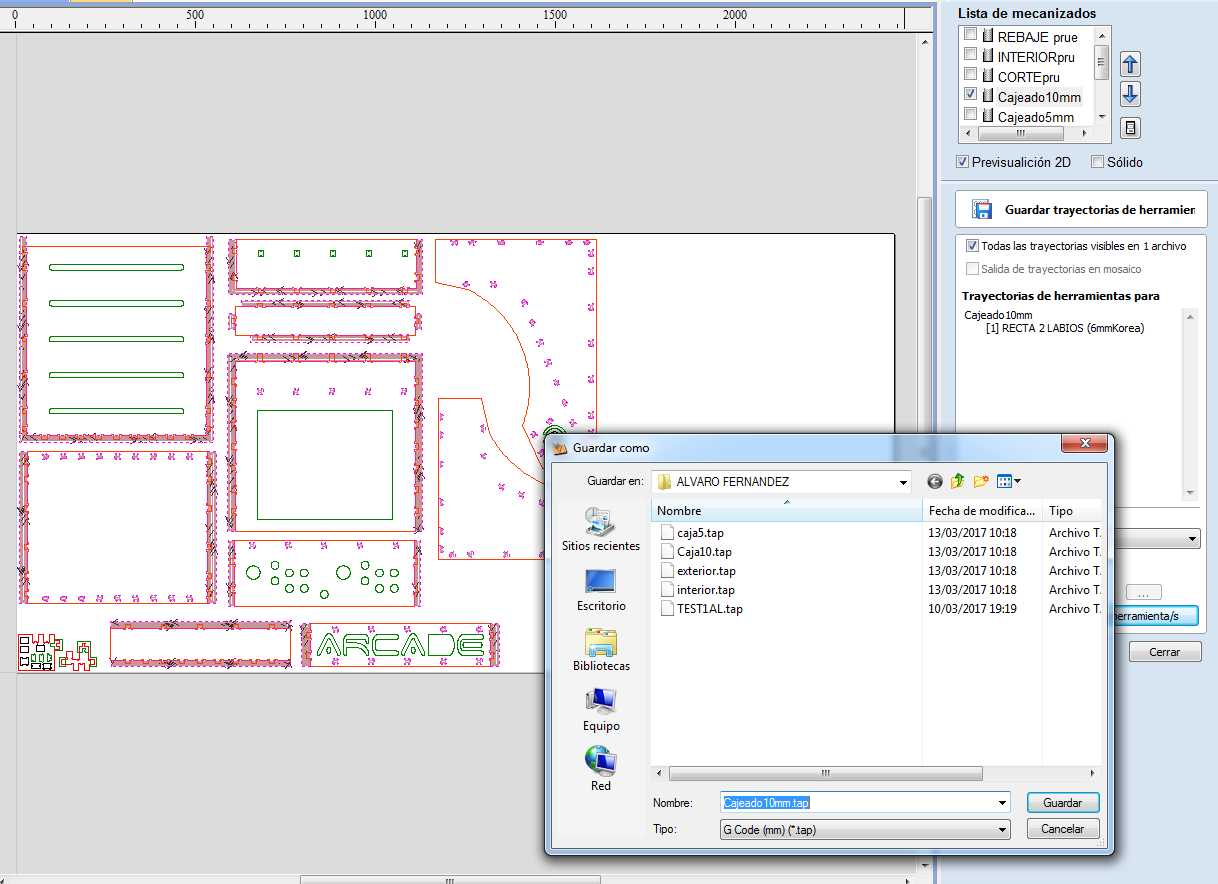
export the file, the file extension is "Gcode".
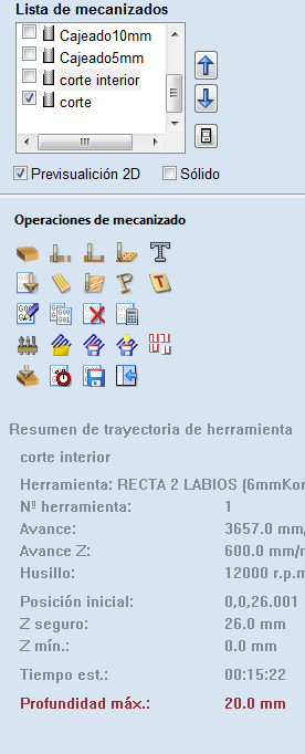
I can see a summary of the cutting time of all the machines, in "cajeado10mm" layer the time is 54:21 min, to have a good design of this object the cut-down time should be shorter and adjust it to the measurement of the tool and perform fewer cut-downs but larger.
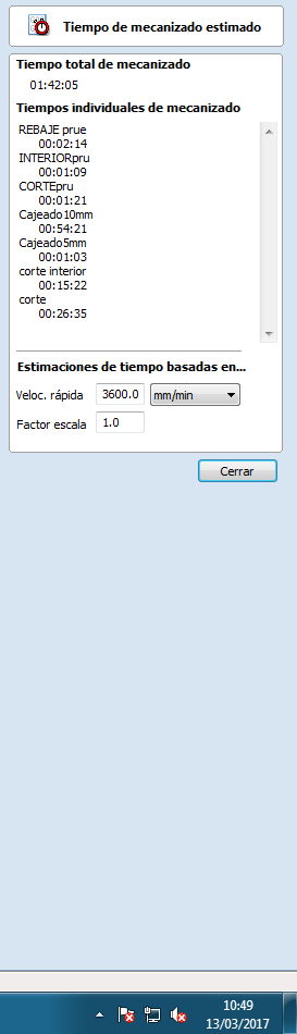
Final cutting time.
--- Steps for milling in CNC TEC CAM 1000 Series ---
-Link of the machine model series.- 1. turn on the machine,
2. take home
3. move to the center to load the milling cutter
4. Once placed, calibrate the z-axis
5. Once loaded move the head to the end and load the material
6. Place the strawberry at the desired point and mark the new relative origin.
7. Turn on the vacuum pump by checking that it is properly attached to the bed.
8. Insert the usb with the file of movements of the machine.
9. Turn on the chip remover
10. Send to cut, enter desired milling speed and keep it running smoothly.
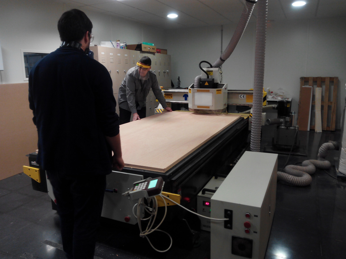
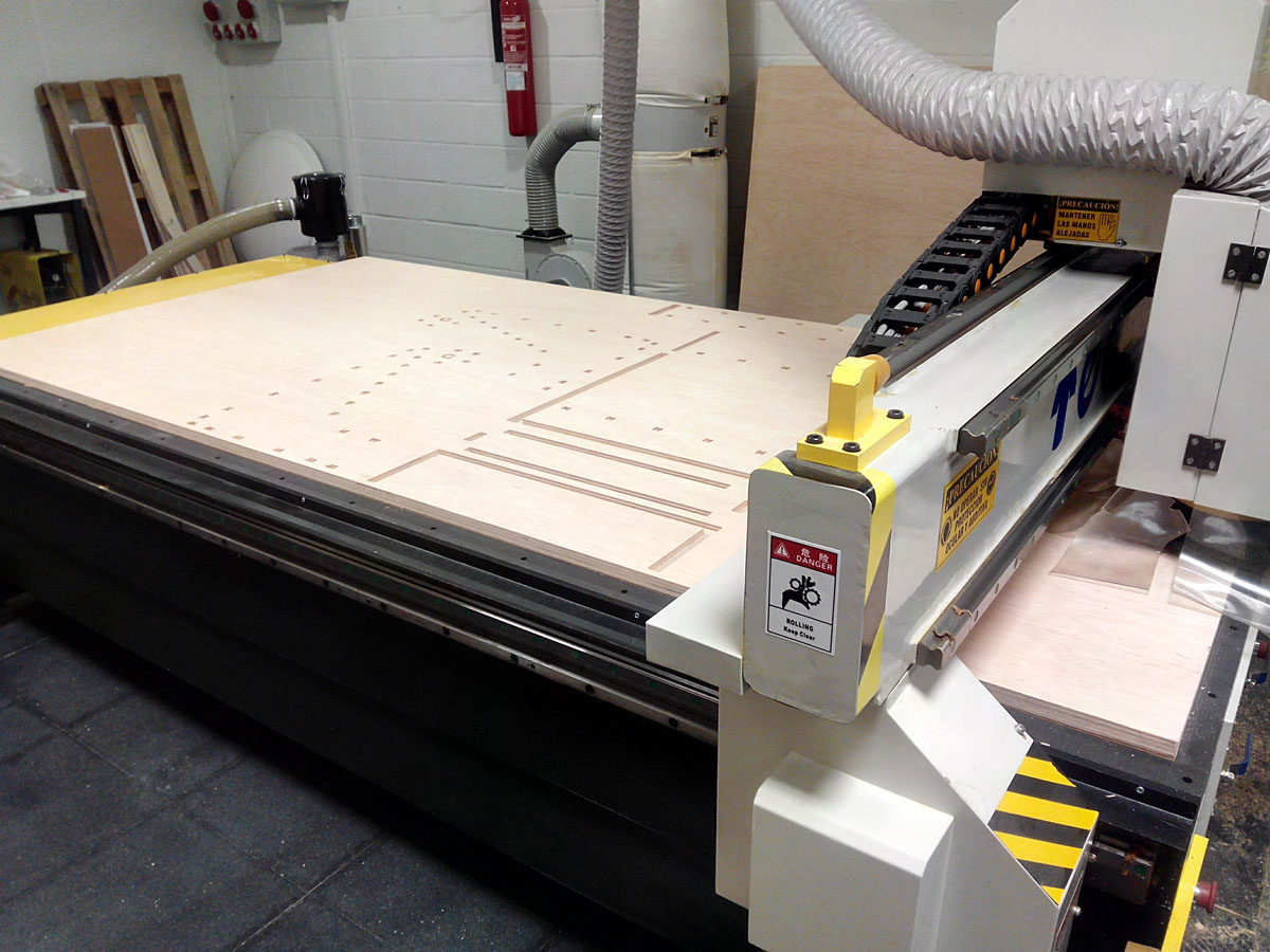
Putting the material in the cnc.
Process of preparing the CNC
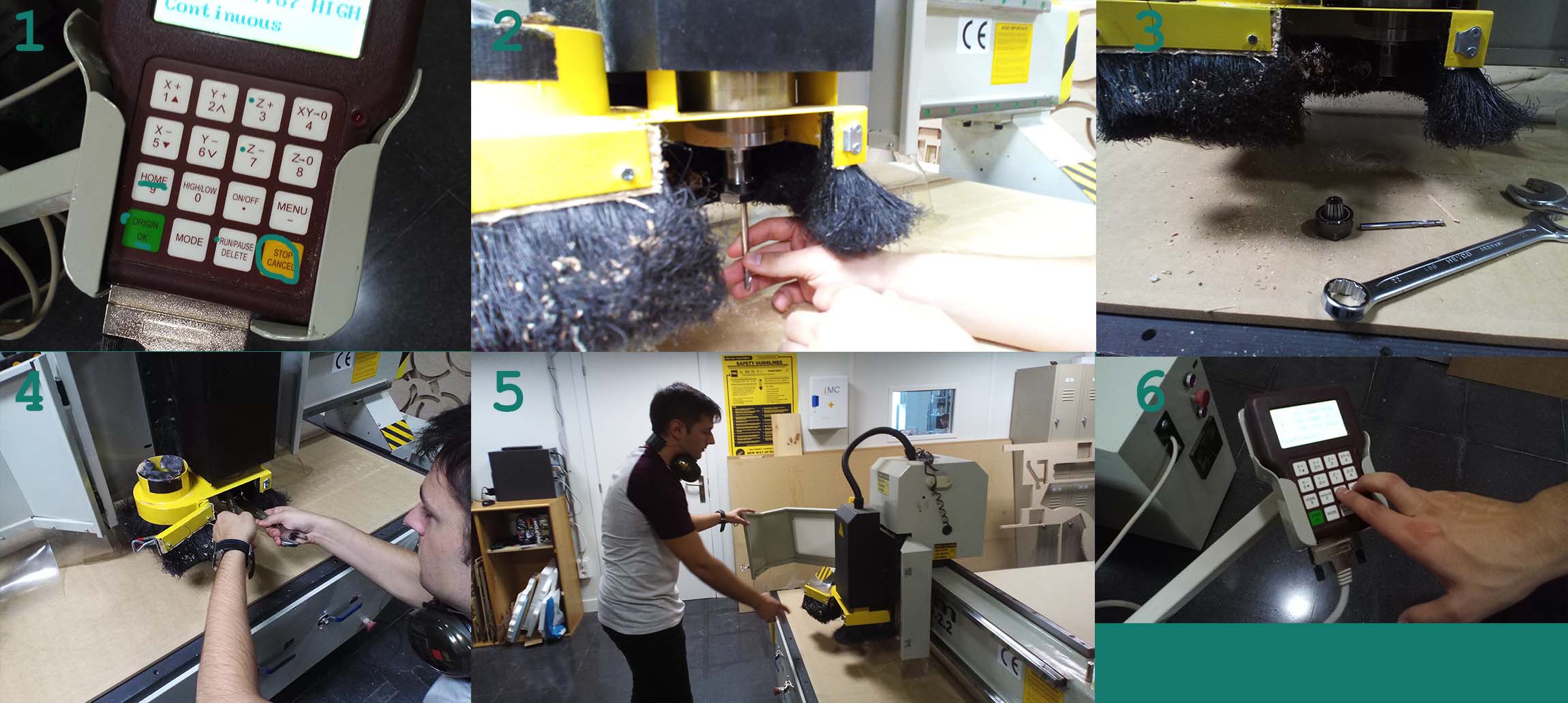
photos:
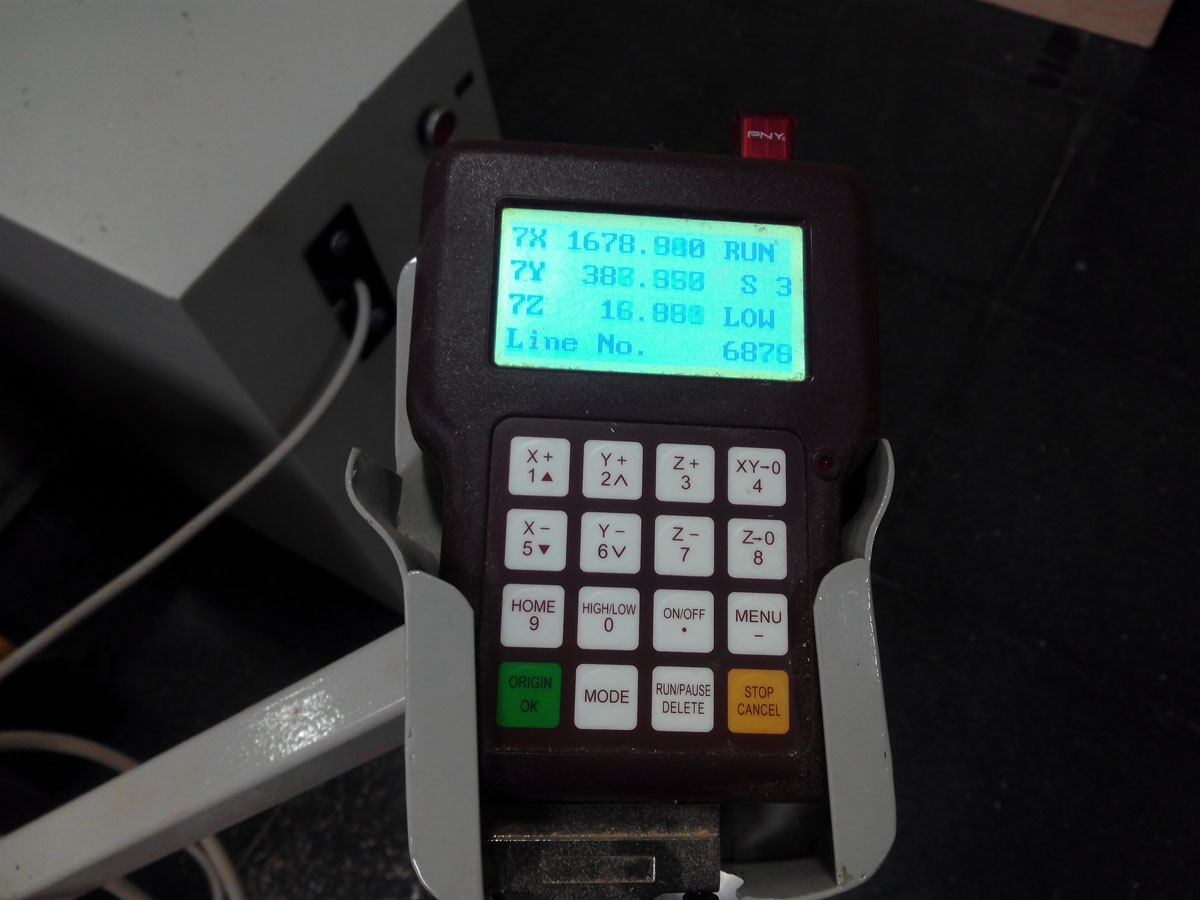
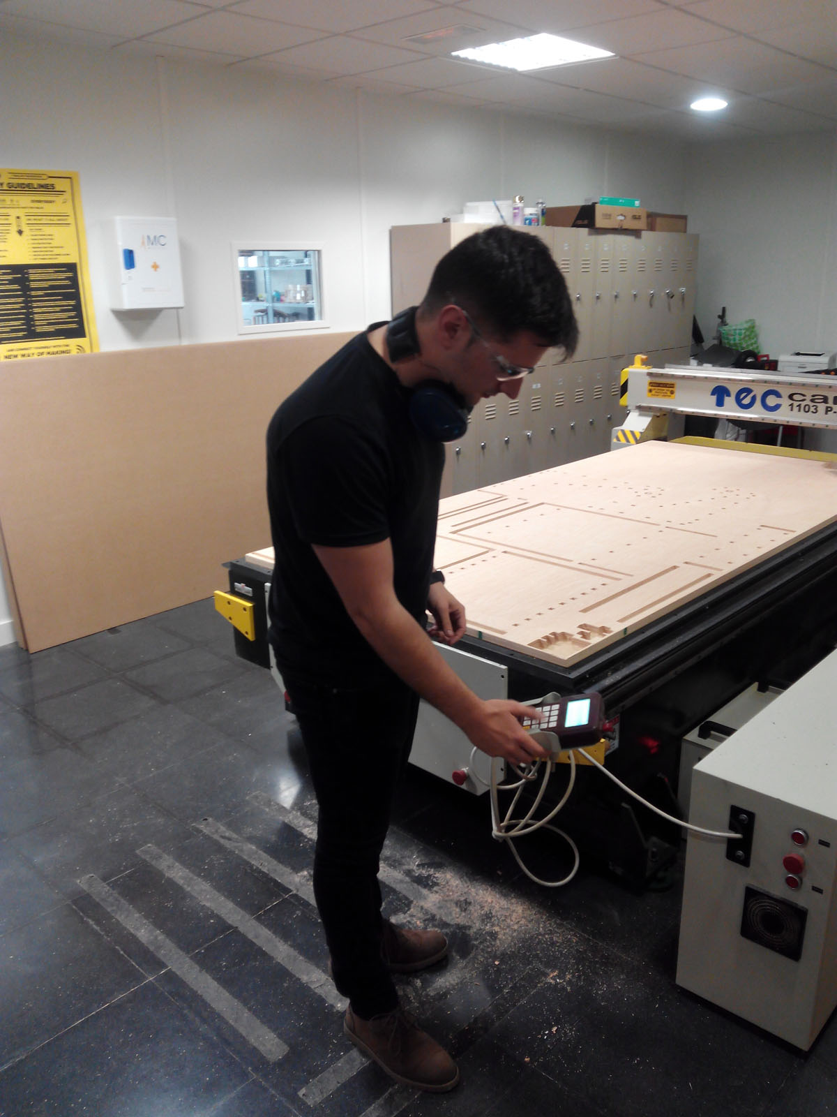
1. With the control knob I can control the position of the machine and start to cut, stop, calibrate the axis, move it in x and y and establish an origin, choose cutting speeds in progress ... etc.
2. I open the safety doors to change the cutter, or put a new one.
3. I will help with wrench to loosen and place the cutter.
4. Placing the cutter.
5. Closing the doors.
6. to calibrate the source in z, see video.
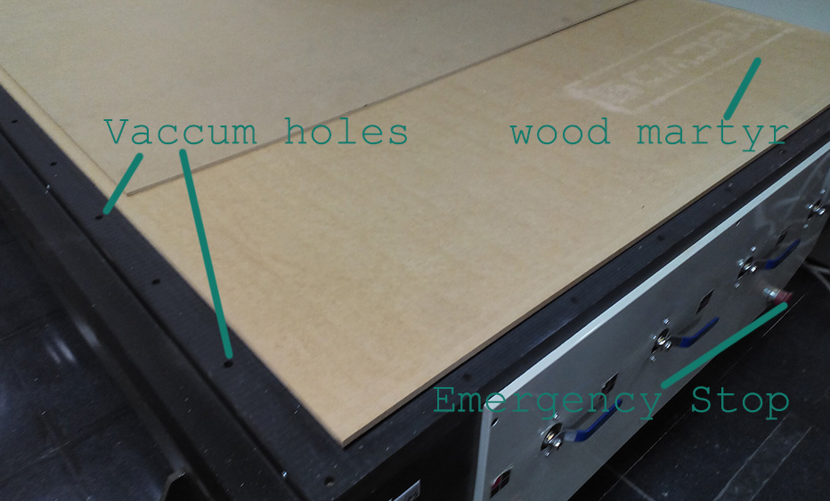
In addition the machine has another fundamental accessory such as the vaccum pump
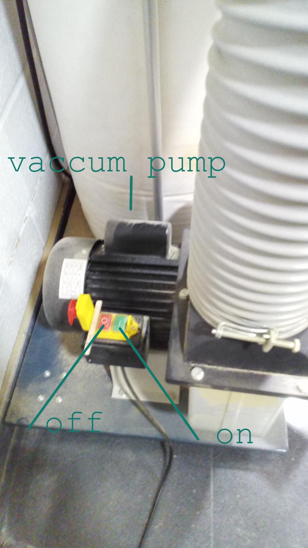
with holes in the table to keep the material fixed, the wood martyr protects the table and lets the vacuum pass through being porous.
The order of sending the layers to the machine will be as follows:
1. Cut-downs
2. Interior cuts
3. External cuts
Sending the file.
The board is attached to the table for a vacuum system that incorporates the machine, a compressor sucks the air under the table and through holes is distributed evenly, the "martyr "or table that I use so that the milling cutter does not cut the table is a porous wood, which makes the material that is placed on it is glued to the martyr and the table and it does not move while the machine cuts.
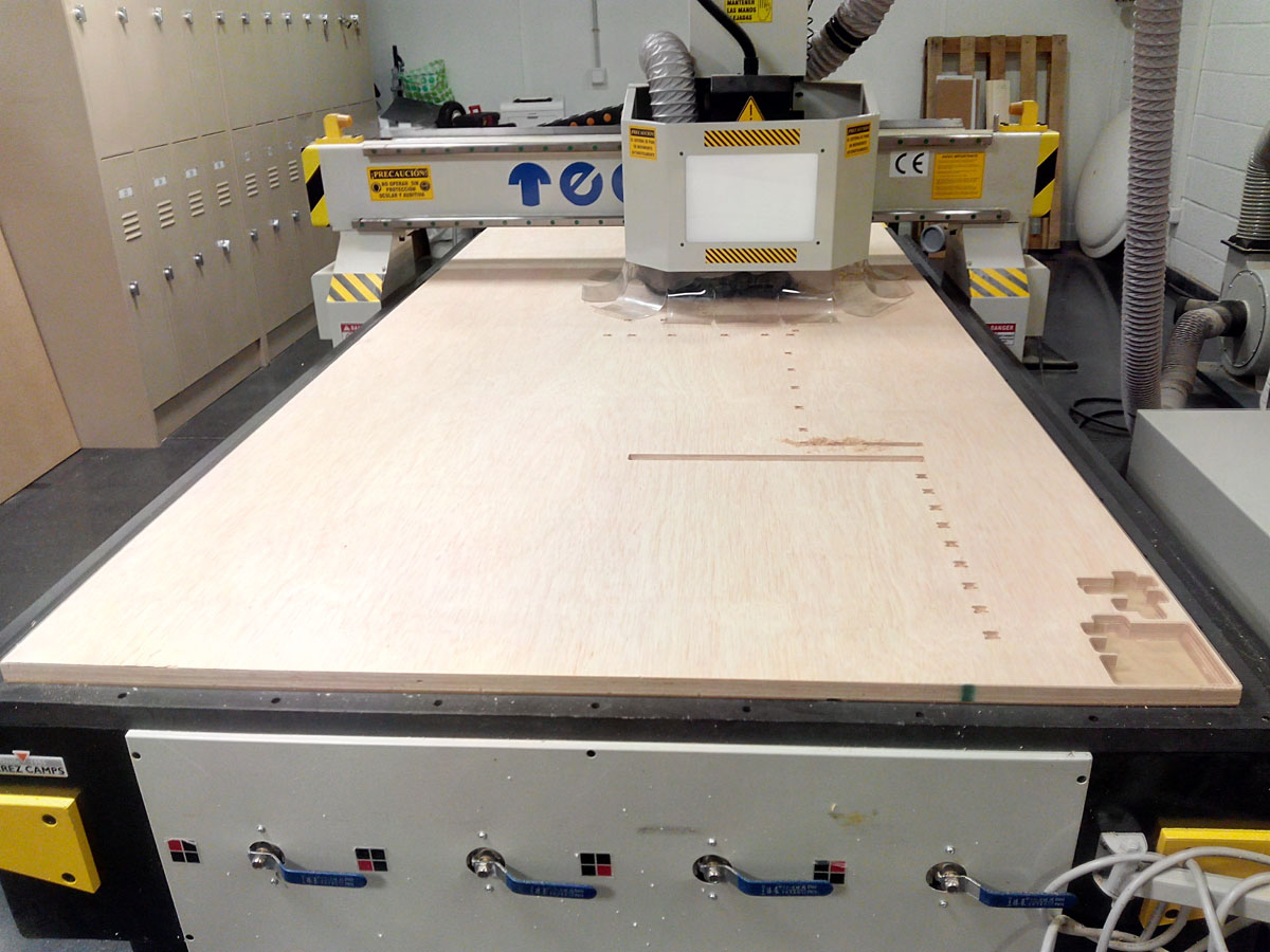 Cnc Doing the cut Down.
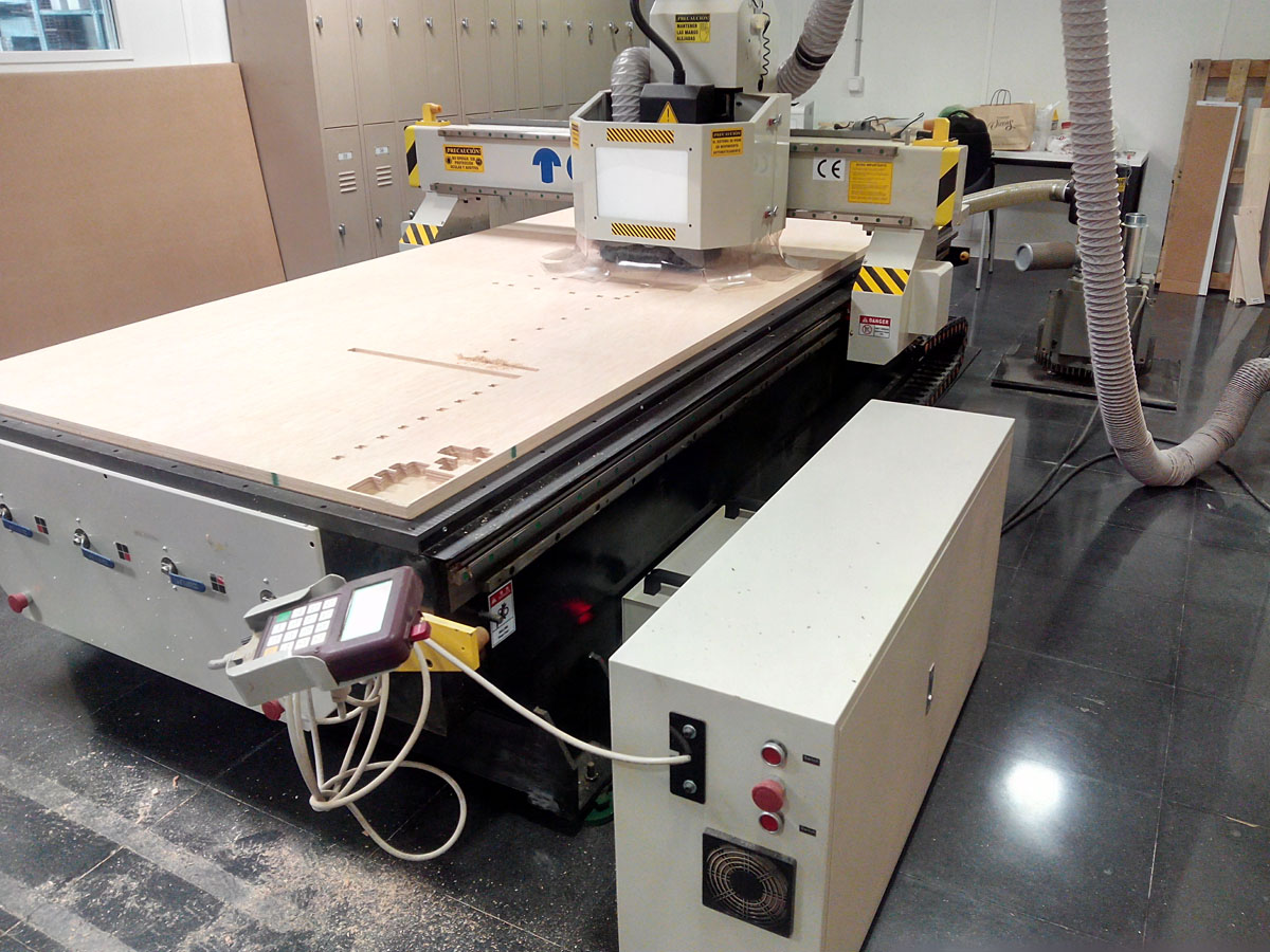
Cnc Doing the Interior cut.
interior cut.
sending the exterior cut.
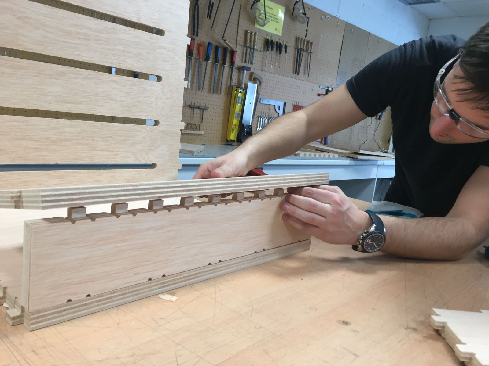
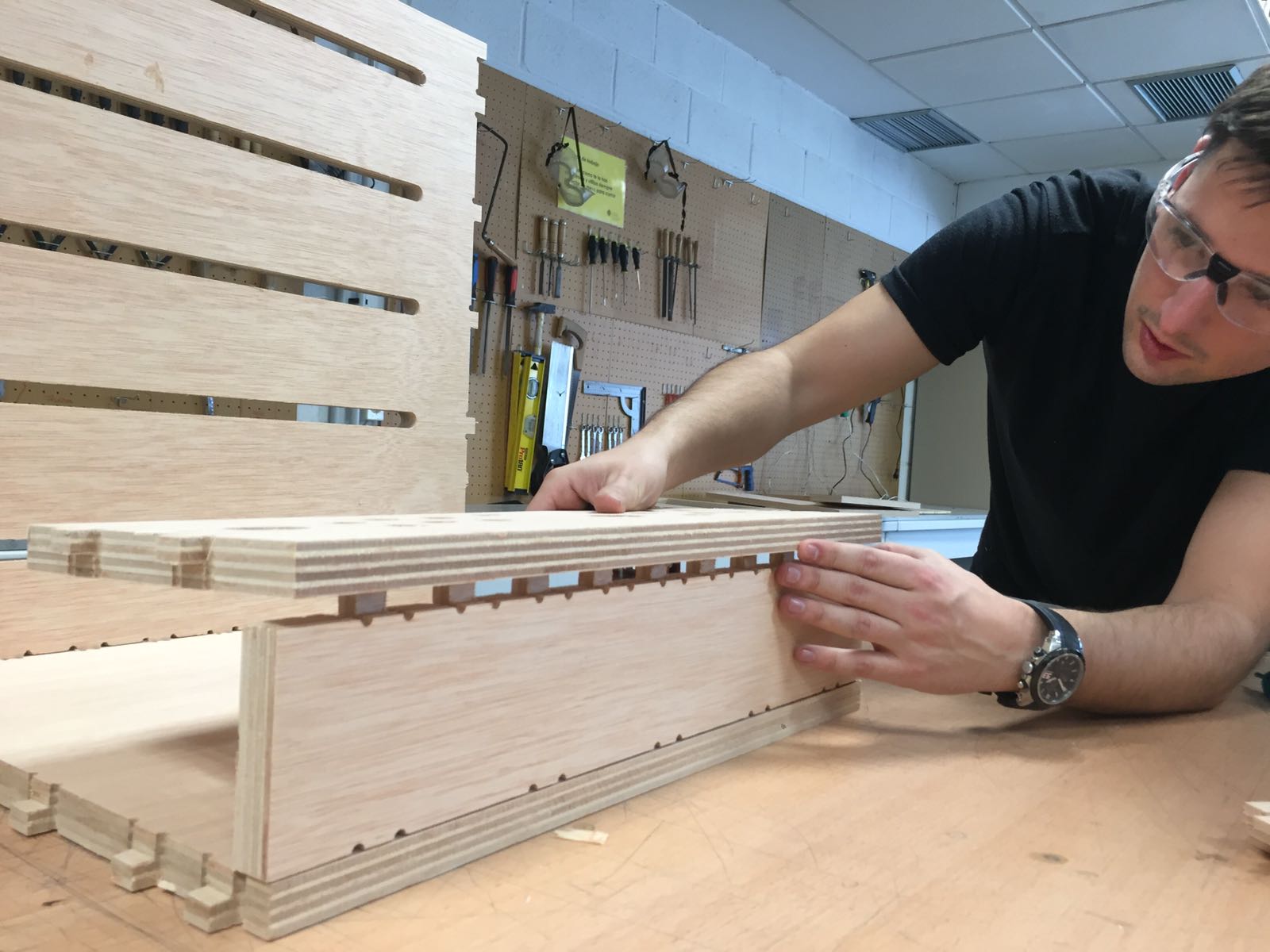
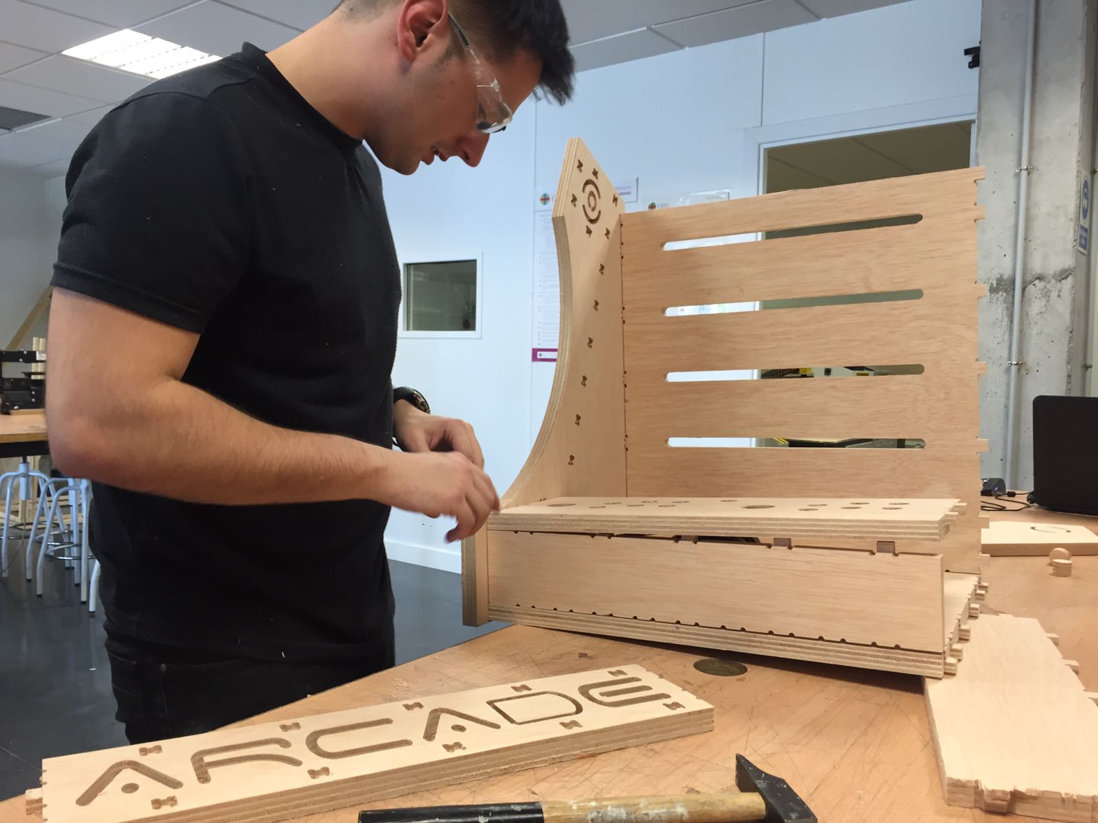
Assembly:
Remove the tabs with a cutter, and sand the edges with a sandpaper.
Join the pressfit following the drawings and helped me with a rubber hammer to fit the pieces.
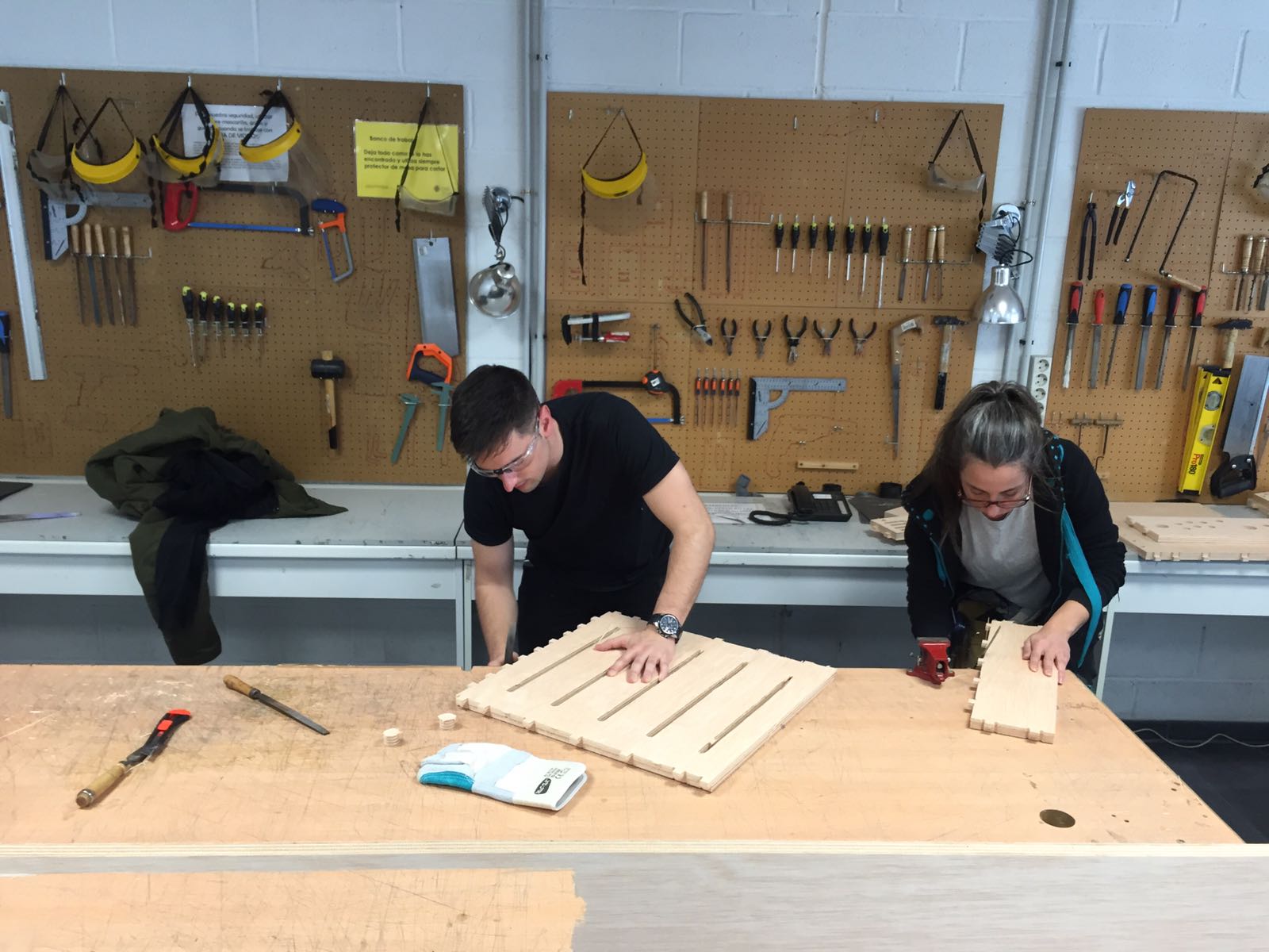
Sanding the wood to remove the remains of the milling eith the help of my partner.
Assembly process.
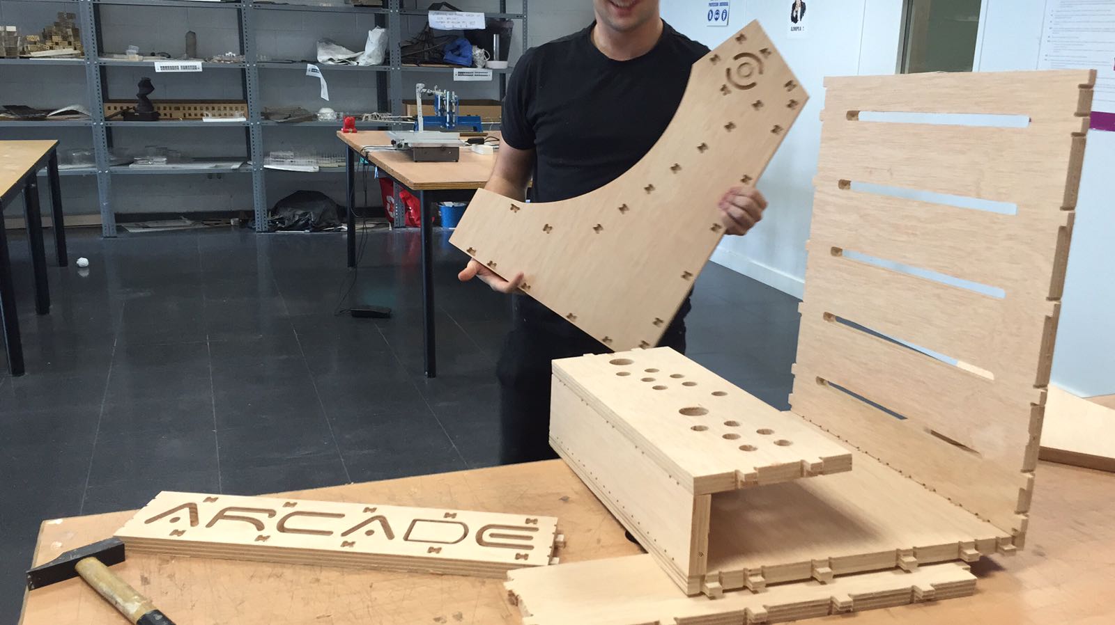
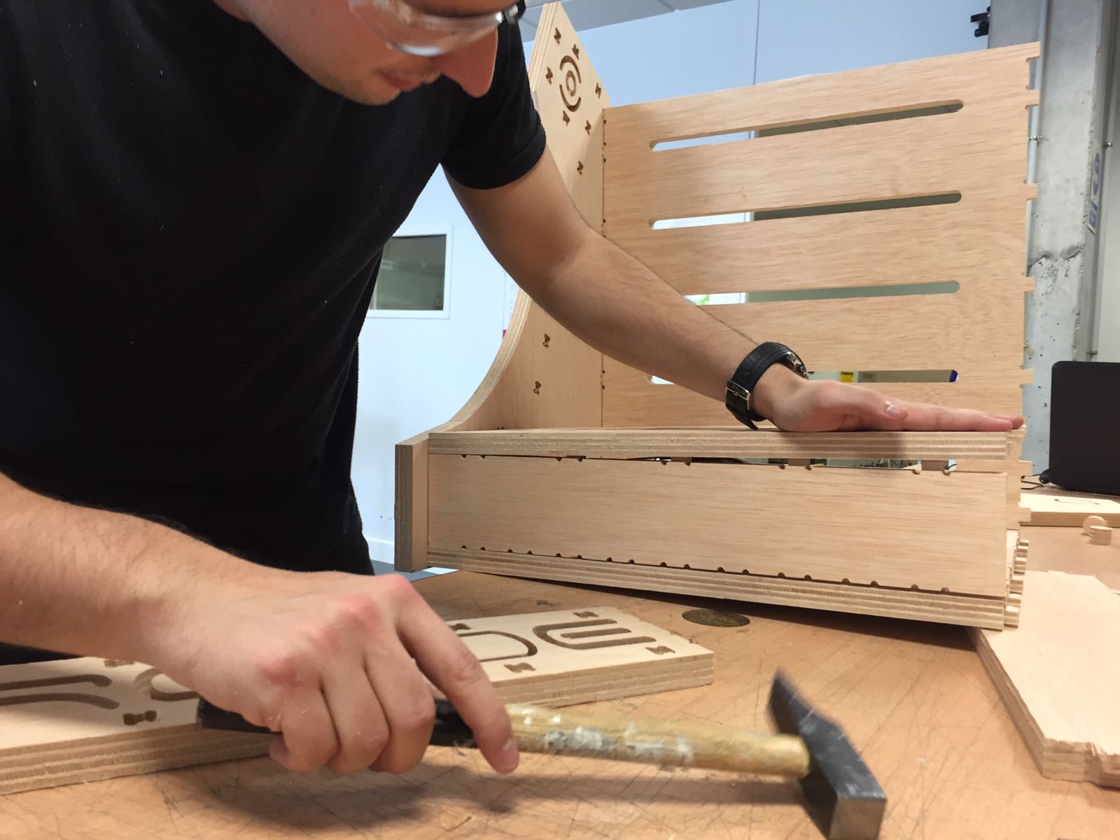
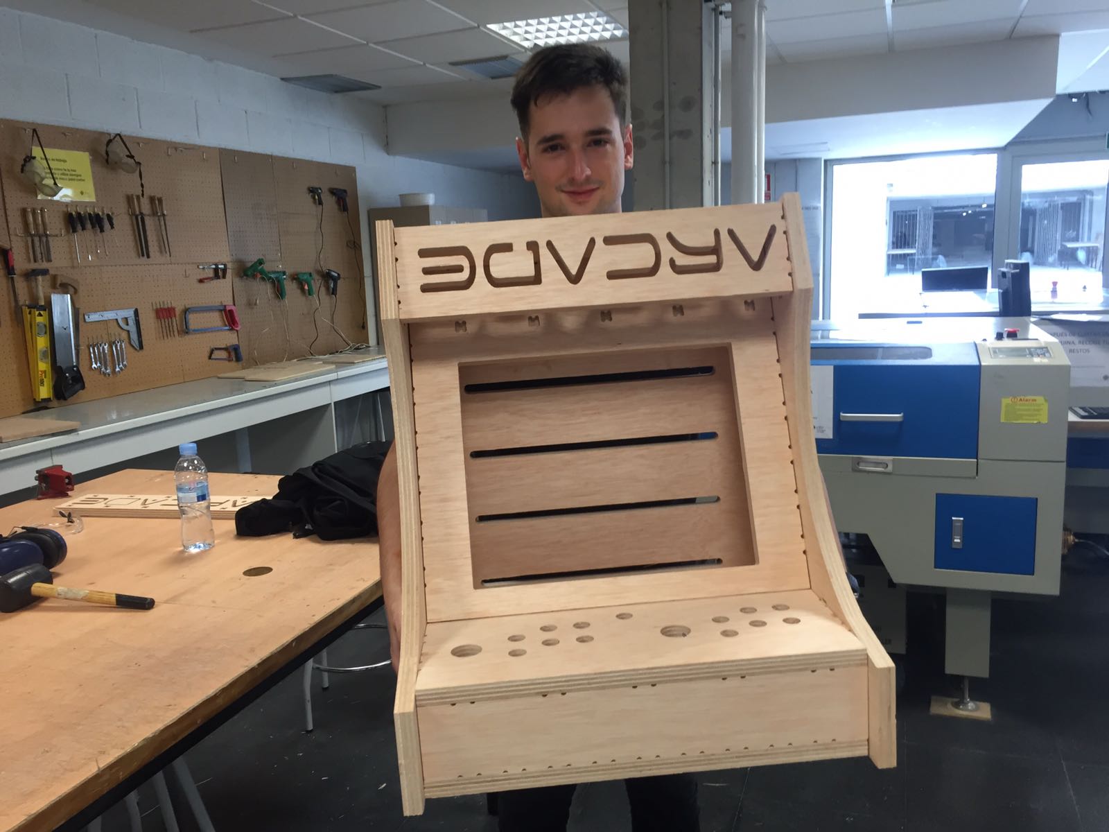
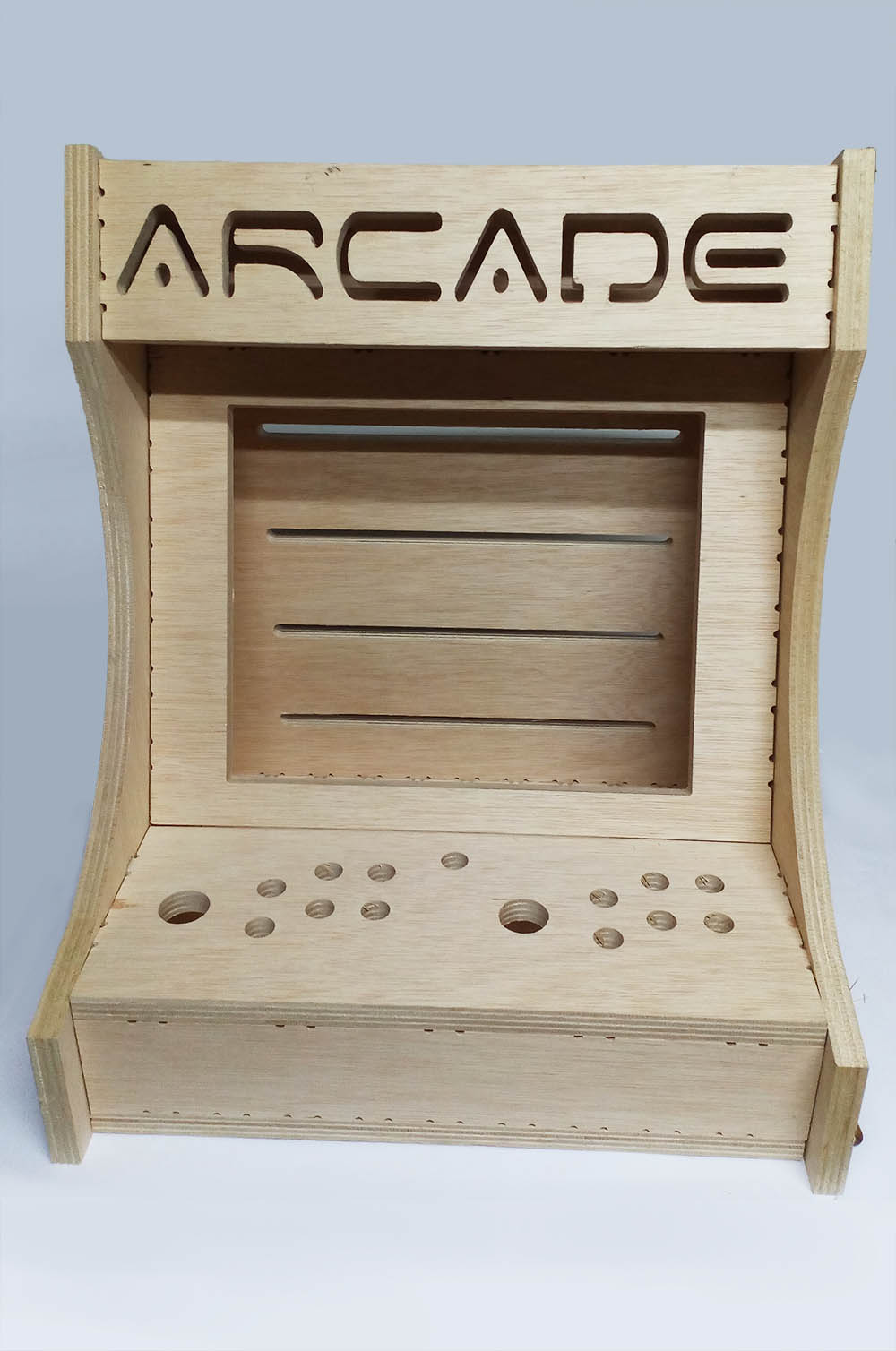
UUUUPPPS !! the letters "ARCADE" are upside down, it's a design mistake, for two reasons.
The first not to have made the symmetrical joints of this piece, this makes it can not turn it around by a variation of millimeters.
The second was that I made the letters without checking it on the 3D model, believing that in the cut design was well placed and yet it was rotated and turned around.
---------In fabrication you always have to check everything.----------
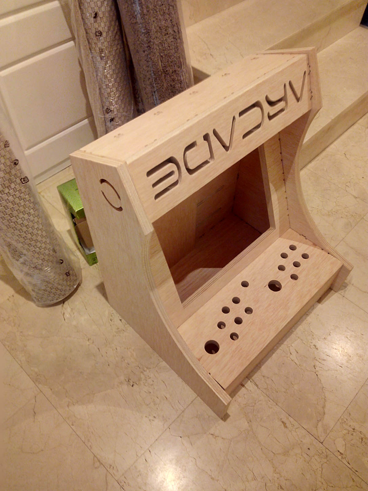
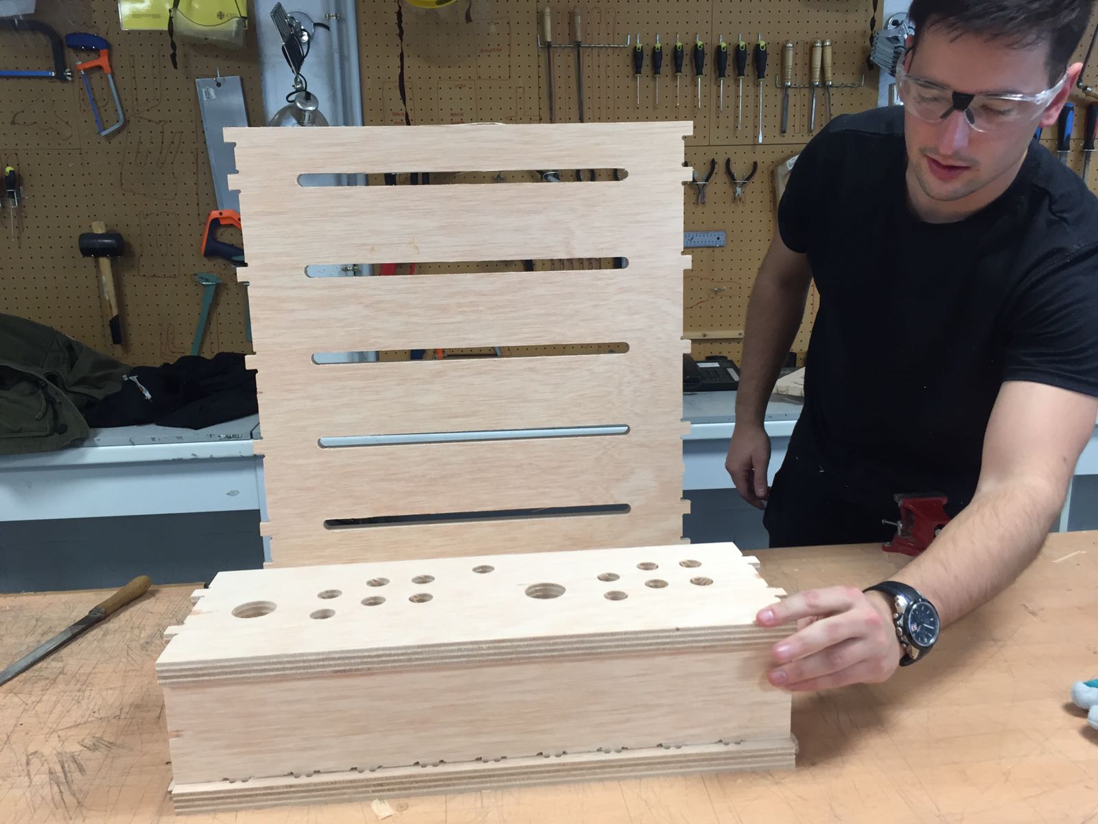
My arcade bartop case.
the joints are beutifull.
Update:
I have made the missing part again, this time after editing it I made it again in 3D and put it in its place to check that it fits perfectly.
It is a complicated part because it must be milled upside down and ready to be turned around.
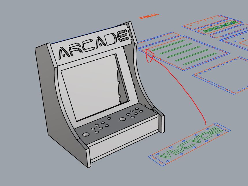
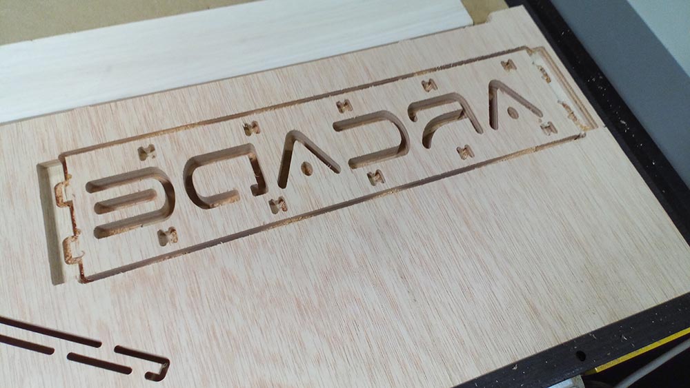
I exported the plan in dxf, and I cut it again, here some screenshots of the process.
It was all right because I came back to remember again how the CNC machine and Vcarve file preparation software was used.
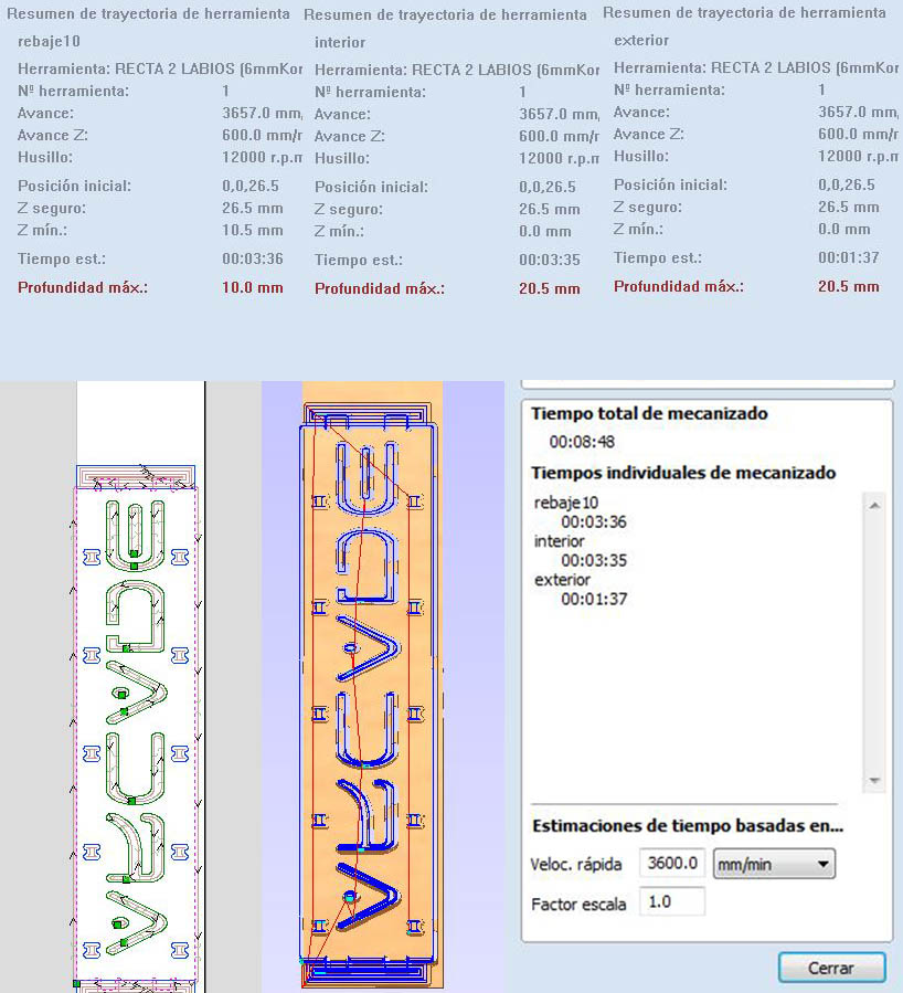
the total time to make the part is 8 minutes, are three layers of cut.
Conclusions:
-- The cutter to be of 6mm some cuts can lower of diameter and adjust it to the cutter to optimize the time.-- Also on the other hand in the planes there are too many recesses, the time it takes to make them is too much, you have to optimize where the recess is made to waste less time.
-- The joints did not need to make so many and so small, would have been worth doing less and something bigger, to lose less cutting time.
-- You have to make sure everything in 3D even if they are small things because if something can go wrong it will go wrong
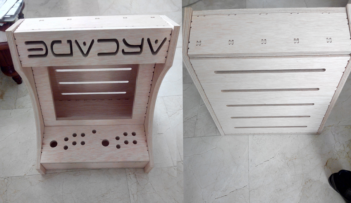
"Hero Shots":
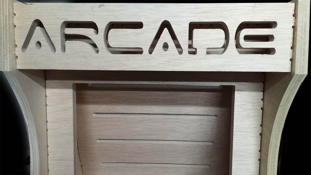
With the correctly placed.
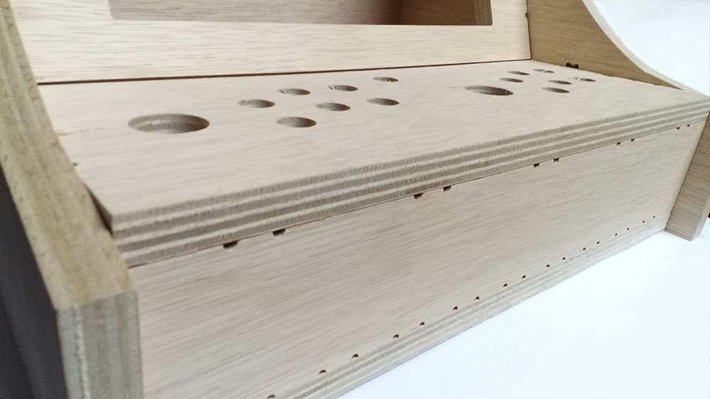
Detail of the joints
My final arcade bartop case.
Files:
dxf of cut plans Arcade Bartop Machine.
3d model arcade machine
test1 dxf
test1 3D model
New part in the correct position