Assignments:
- Make lasercutter test part(s), varying cutting settings and slot dimensions- Cut something on the vinylcutter design
- Make, and document a parametric press-fit construction kit
- Push in this Button for see the laser group assignment.
Vynil Cutting:
Objetives - Cut something on the vinyl cutter. done
I had already cut vinyl to make a t-shirt in a class activity a year ago for a university class with the same vinyl cutter.
There were things that I did not remember, like some of the buttons and how to prepare the document.
We had a few vinyls of various colors I used black and yellow vinyls.
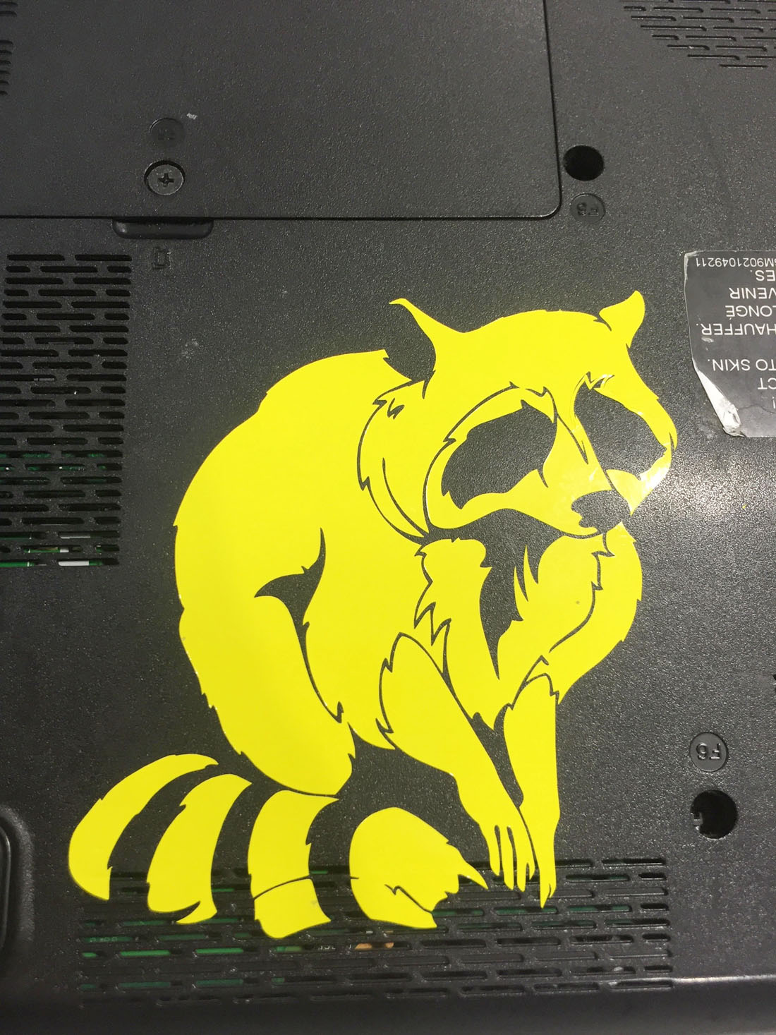
I have a black and a silver laptops,I wanted to make me stickers, and the stickers would be about the best animal in the world, the raccoon.
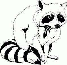
My first raccoon
I got online this drawing of a nice raccoon from this website:
---- Link to Raccoons drawings -----.
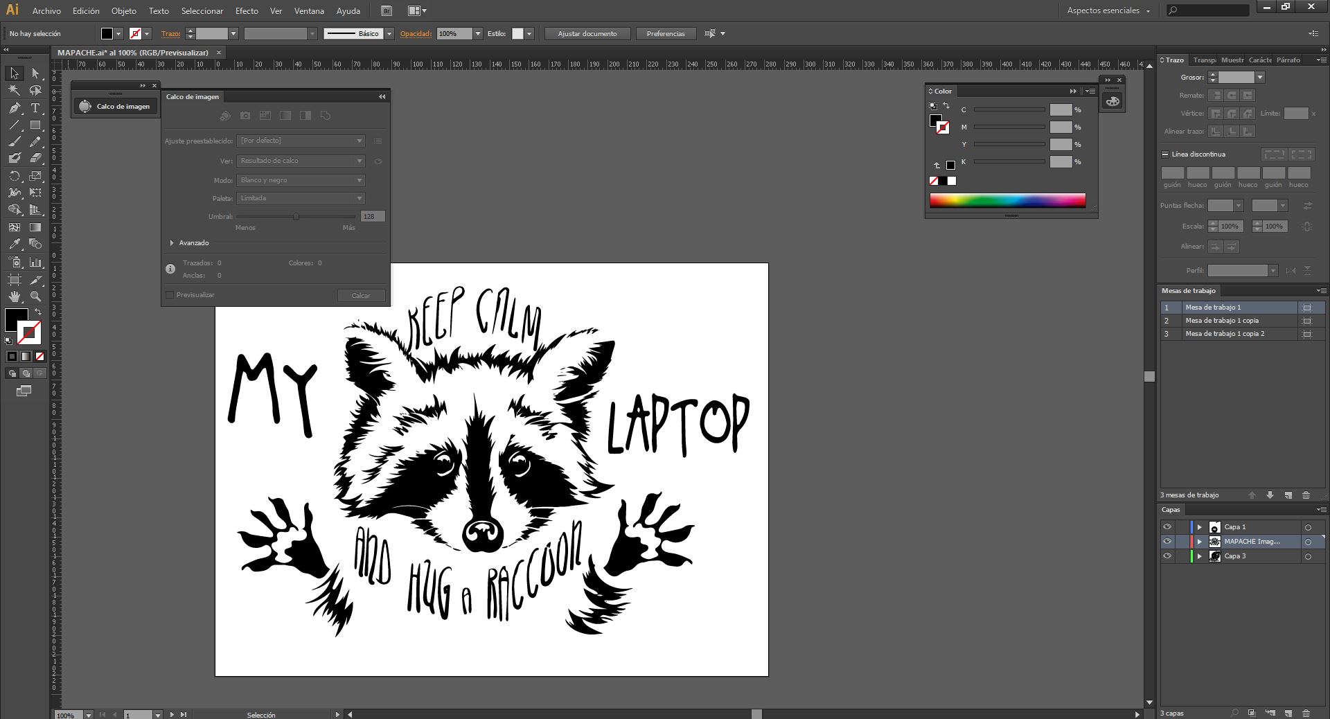
The target, as my laptop is black do what goes white in the drawing on yellow vinyl, for that we will have to clean the image, vectorize it and take it to the fab modules program.
By "Image Frame" I can control how to vectorize the image, and there are different presets already defined, as a black and white logo, that works quite well.
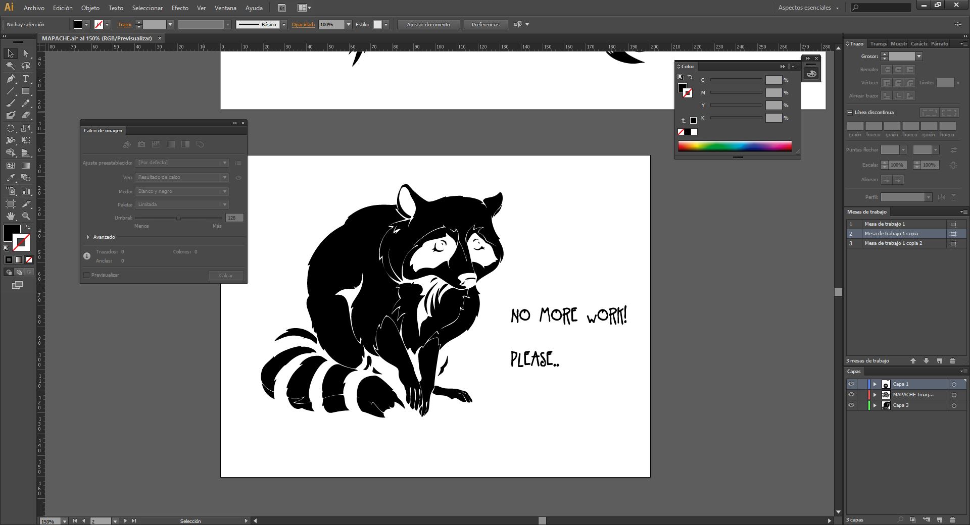
Converting the png image into a vector image to send it in .svg, My raccoon thinks that it's too much work
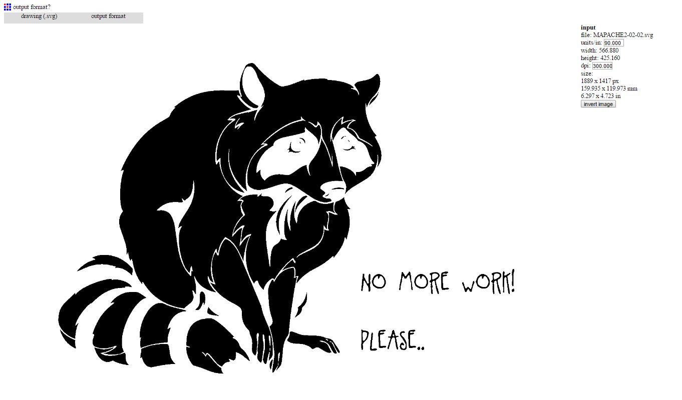
I invested the colors of the image to cut that part but anyway it does not matter since you can choose which part of the vinyl you extract later, and even the fab modules program does it.
Export to .svg which is a vector format that works well, however other formats can also be like png although my colleagues had problems with these others.
How to use vynil cutter:
Steps to use the vynil cutter machine.
1. Turn the machine on and adjust the vinyl
2. Align the vinyl and tighten it with the roller
3. Choose the internal configuration parameters of the machine
4. Go to mods and choose the parameters along with the file.
5. Perform a cut test
6. If it has been successfully sent, send the file.
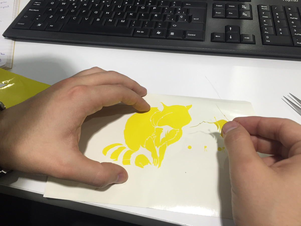
7. Remove the vinyl with care and tweezers
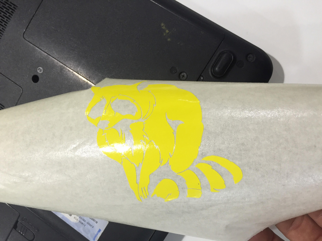
8. Use special paper to transfer.
Parameters used:
force(g) : 80
velocity (cm/s) : 2
tool diameter: 0.25mm
Number of offsets : 1
We introduced it in Fab modules.
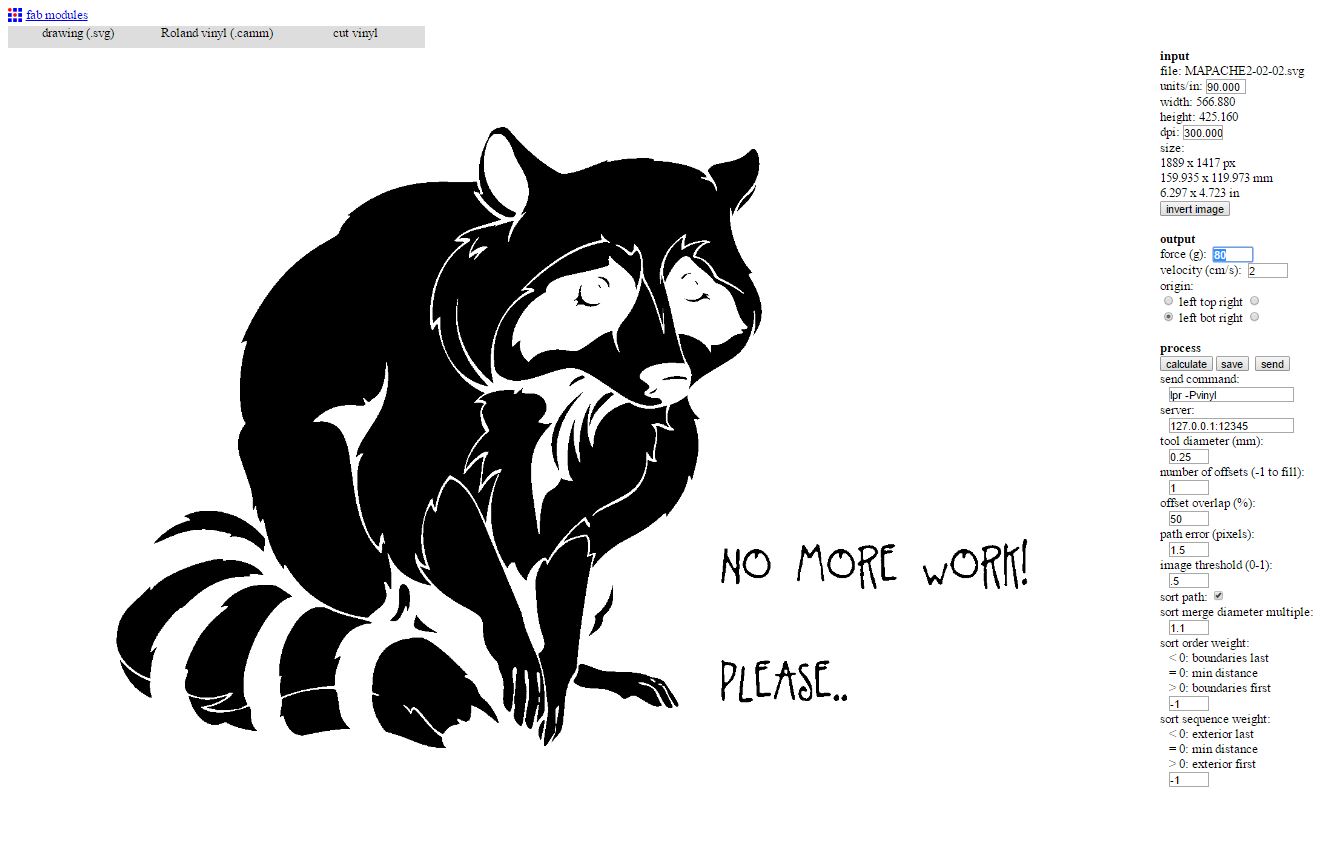
We indicated the presets, previously we tested with the plotter in class and the force that we had to give it was 70g.
Perform another test, the circle detached without much difficulty of the square.
I hit send and began to cut.
This was the result:
OOPS! the lettering are very small and difficult to take away.
With the special paper the image is transferred by squeezing hard and moistening it slightly to the final surface.
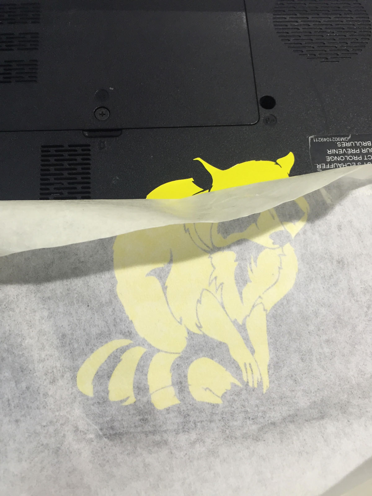
like this.
final result.
Things to improve: Do not make the drawing so small because the small things in detail do not work, apply some more force, in the parameters of the cutter.
Tighten further and more carefully when removing the vinyl debris, moisten the paper better when transferring.
Be more careful.
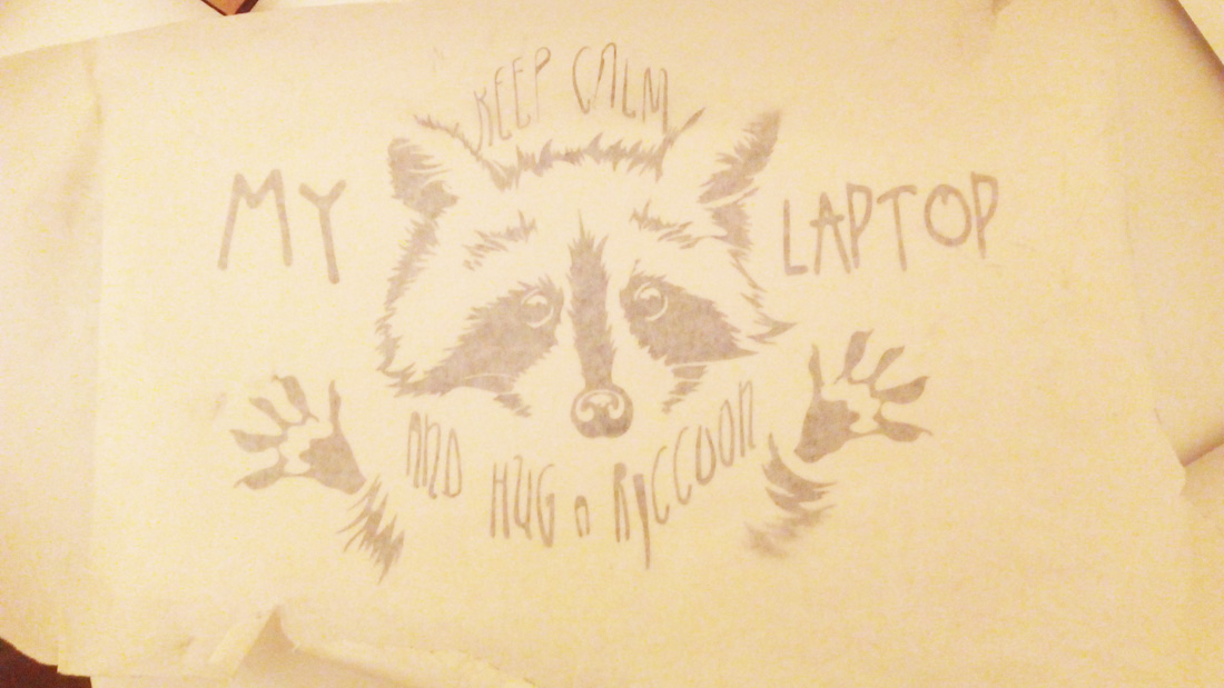
Second Chance:

its so cute.
Following the theme of the raccoons, I did with this photo, and I wanted to do the same steps this time improved.
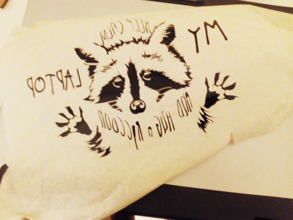
Vectoring the image.
Enter the phrase, My Laptop in font to Little pot, which I later converted into vectors with the text tool to create outlines.
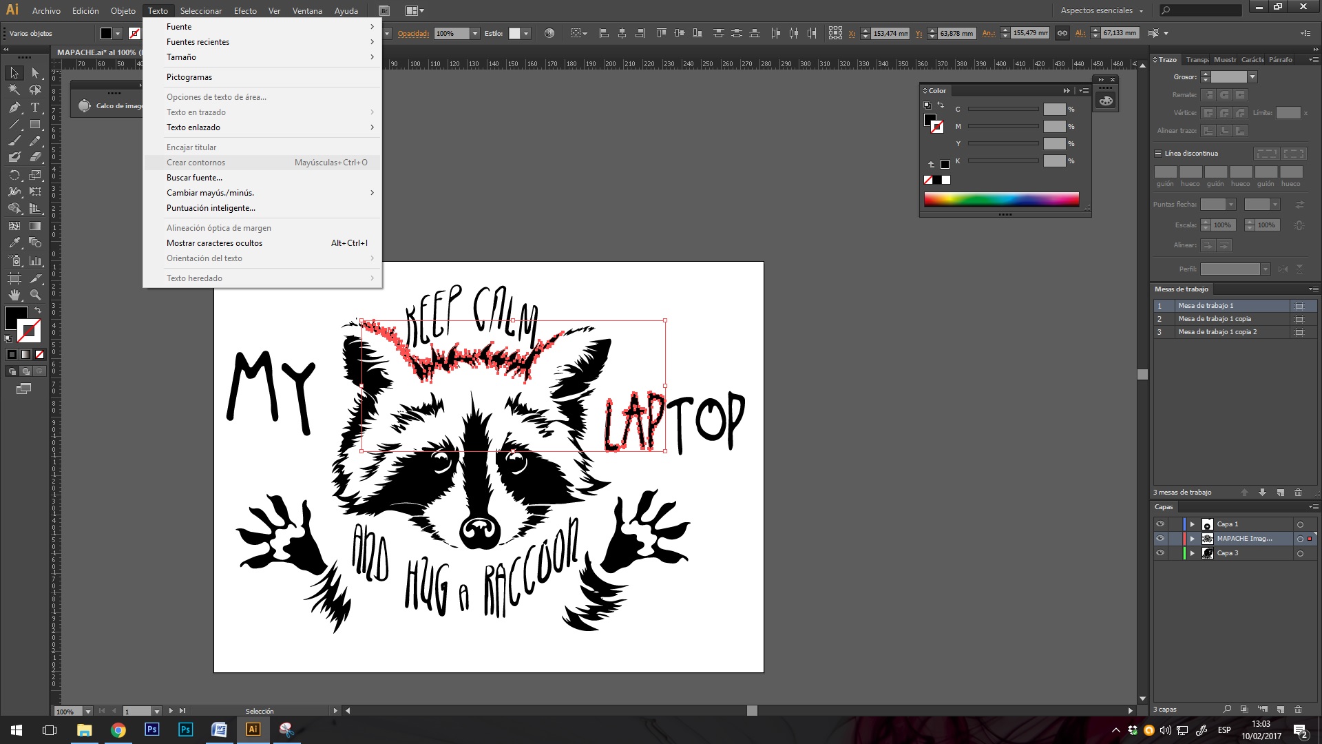
Vectoring the text.
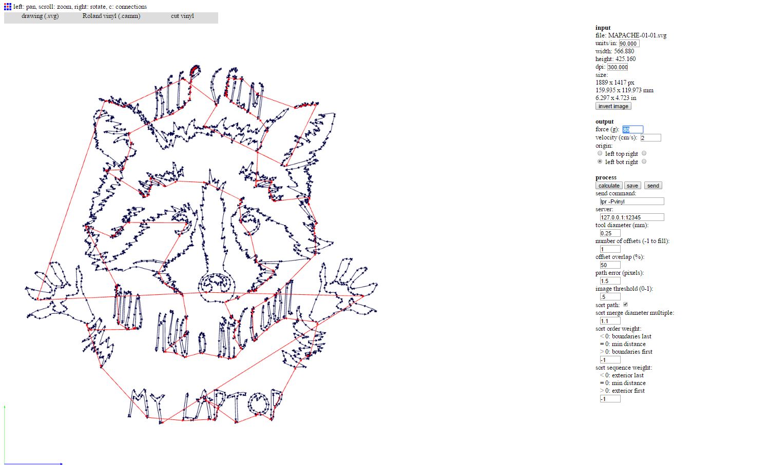
Vectorized raccoon are calculated.
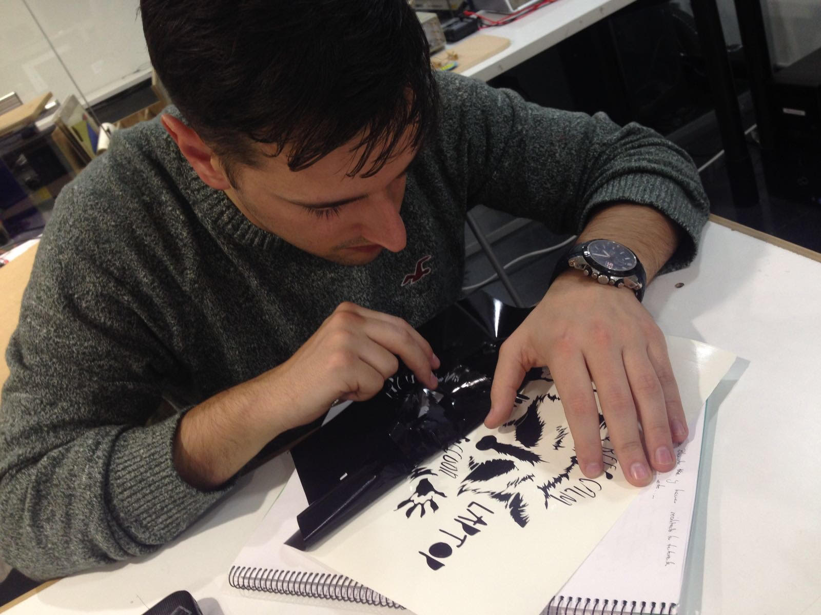
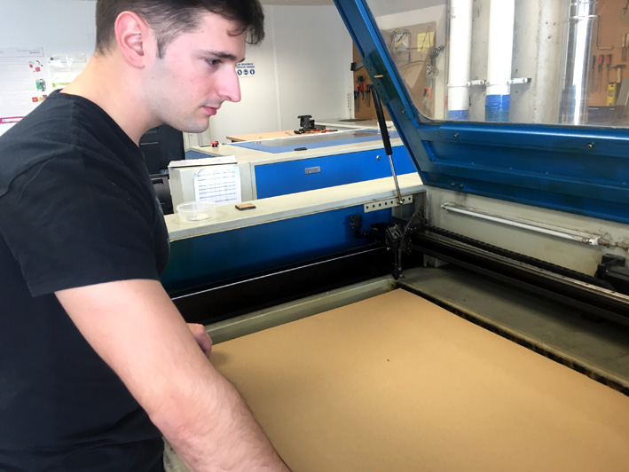
Me at work.
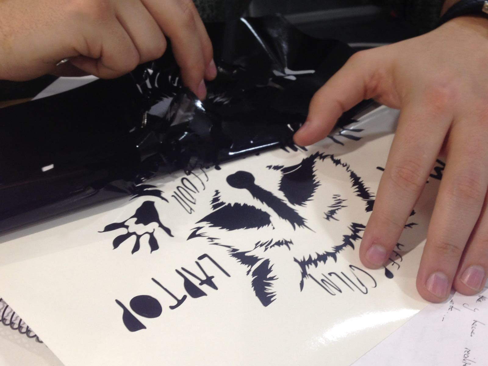
Extracting the vinyl.
Special paper.
Very carefully and applying force and moistening it a little.
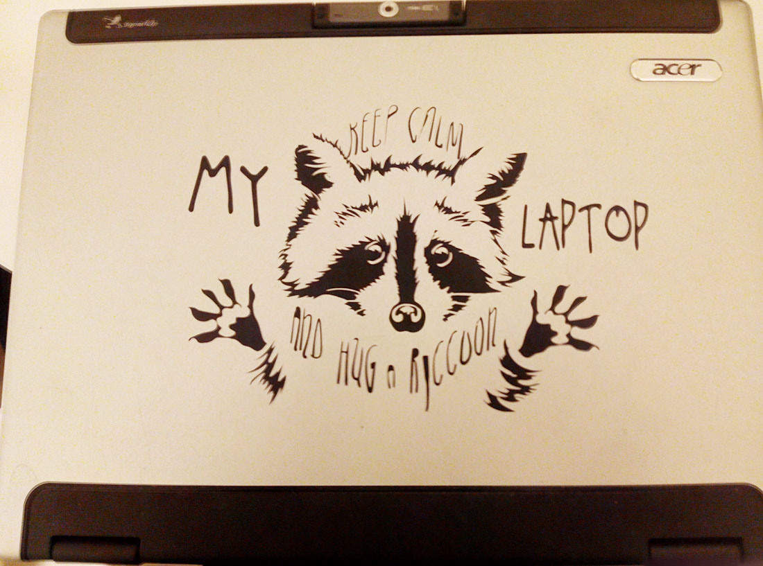
final raccoon.
Laser Cutting Machine:
Objectives
-Group - make lasercutter test part(s), varying cutting settings and slot dimensions. done
-Individual - cut something on the vinylcutter. Design, make, and document a parametric press-fit construction kit, accounting for the lasercutter kerf, which can be assembled in multiple ways. done.
- Push in this Button for see the laser group assignment.
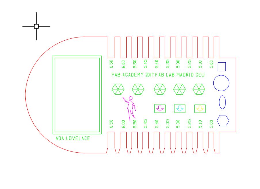
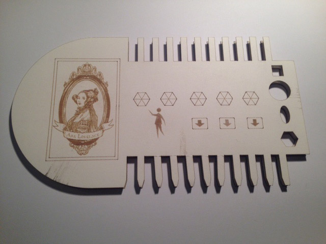
In group we made a template to see the kerf of the 5mm carton and test the different types of engraving stuffing and cutting, in different materials, wood and cardboard.
For this we prepare in autocad a template to test all these parameters that could also be joined to another created to find out the kerf and see how it engages best.
These two templates, each layer is to make a cut or fill different engraving or to place in order of the machine, and that for example the inner contours make them before the exteriors.
template A
Template B
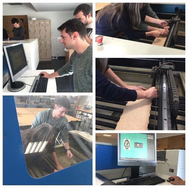
How to use Laser cutting machine:
Steps to use the laser cutting machine.
1. Start the machine and activate the suction and other devices.
2. Placing the material correctly.
3. Adjust the header to the correct distance.
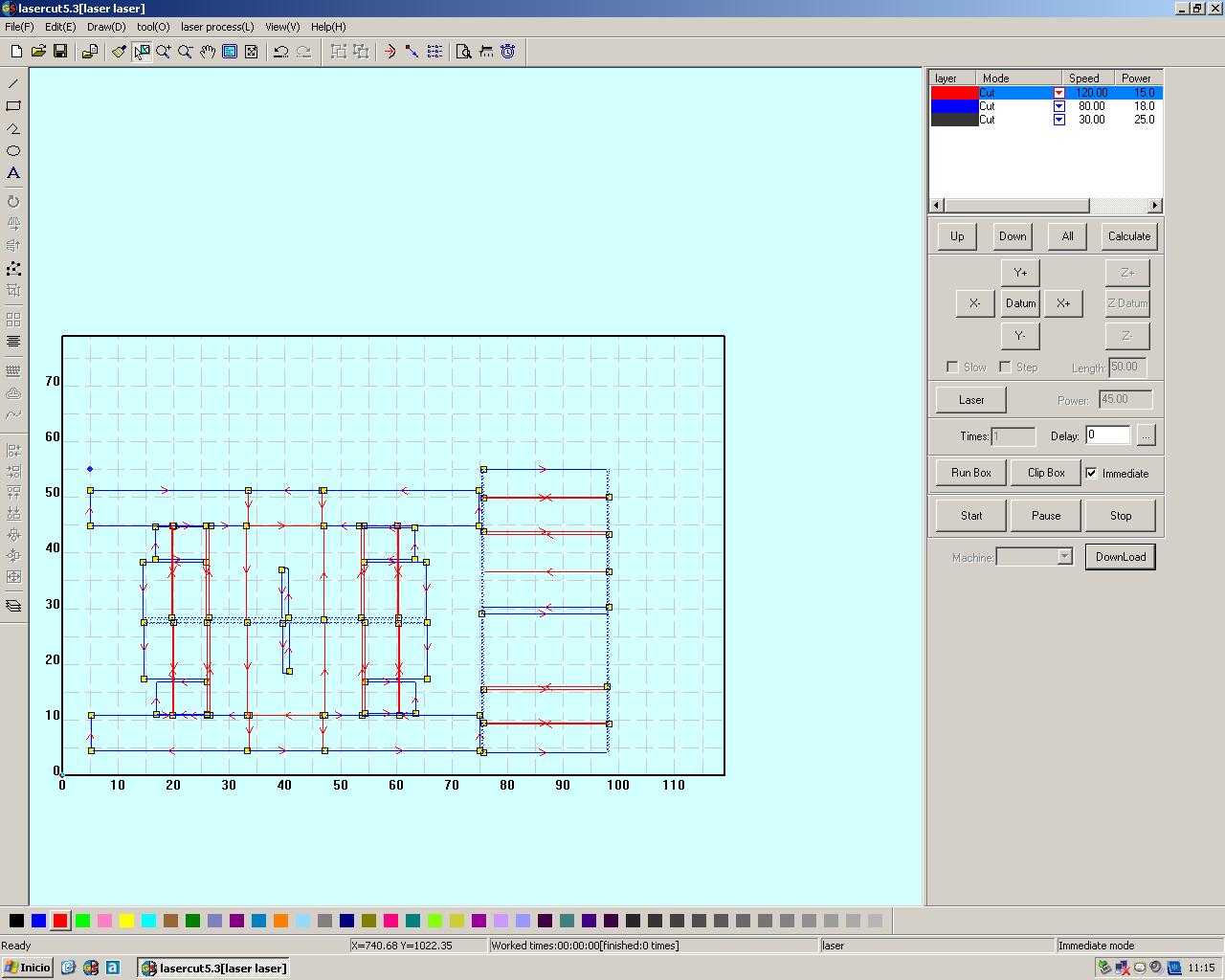
4. Start the control program of each machine, in this case lasercut.
5. Import the file into cut dxf.
6. Place and assign cut values to each layer.
7. Load the information that will be provided to the machine.
8. Adjust the cutting frame to the material and the point of origin of the header (frame and laser actions)
9. Last check and start.
Parameters used:
Placing the material correctly
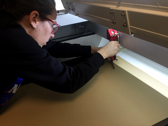
Adjust the header to the correct distance.
Import the file into cut dxf.(this is a file of machine design)
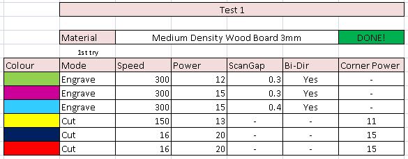
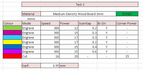
Parameters for MD 3mm
The result
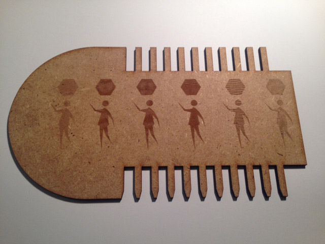
The result
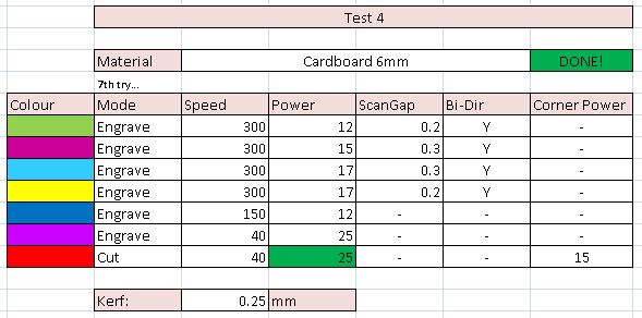
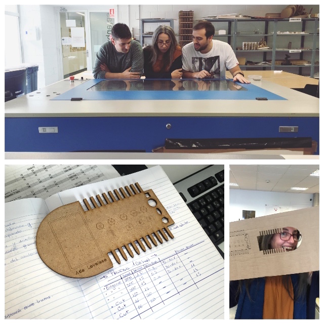
Parameters of cardboard 6mm
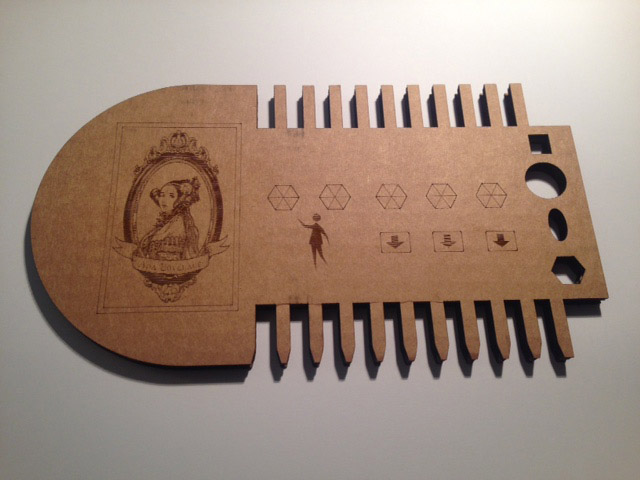
cardboard engraving template b
The result
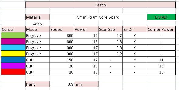
5mm Foam core board
The result
Problems we had: the first was that the letters imported from autocad were not worth had to be vectorized its outline if what we wanted was to save it we solve it by erasing them and adding them from the lasercut software.
The third problem that took us a little more time was to prepare an image to make a fill,
we had problems for the depth of colors and until we passed the image to bitmap and we turned it into tif we did not make the program do A fill with the image, the result was very good.
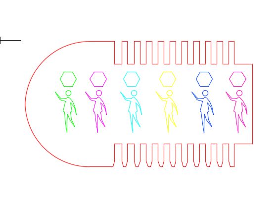
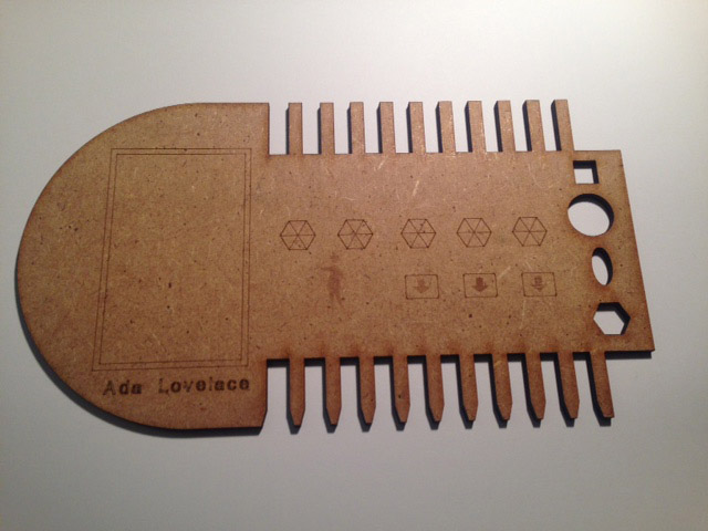
Ada Lovelace the patron of our group that guides us and shows us the way.
An oversight that we had was that when changing the material we did not make a change of template since the cardboard pen and the other cardboard had the same thickness practically but nevertheless the wood sheet did not and as a result if we made two wooden templates would not fit.
So we do the group work and now I'm going to do the individual work.
Individual Press-fit
WORKFLOW:
- Know the shape and design of objects
- Create sketch in Freecad
- Apply restrictions
- Apply dimensions
- Check Object
- Export to dxf
- Laser cutting.
I will make a didactic game for small children with basic shapes and polygons from 3 to 6 sides so they can learn, with letters and numbers engraved on their surface to learn letters and numbers and associate them with figures, in a post process could Be painted.
To do the design parametrically I started with autocad, being a program that I know and have a parametric part that seemed quite advanced.
I tried to make the pressfit pieces I had in mind, I started by the square that seemed the easiest.
The design is simple constraints of perpendicularity, horizontals, verticals and adjust the values of high, thickness, and side.
I correctly performed the square by spending a lot of time for the simple task it was, with the hexagon the same thing happened.
I had a problem with the file and the perpendicularity restrictions disappeared.
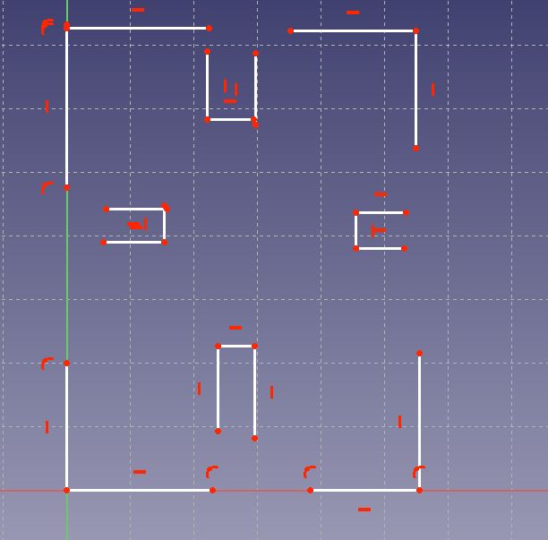
After losing a lot of time I started working with Freecad, a parametric design program that I think is easier to create your object with an idea of how you can build.
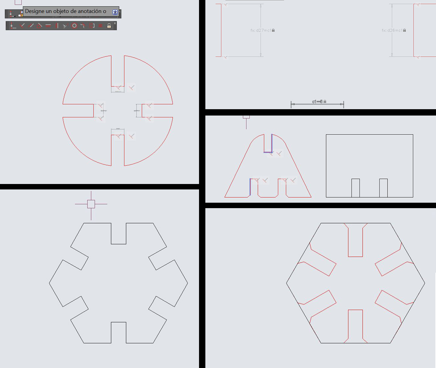
I made the hexagon and the square quickly, the circle I could not perform in autocad I did it making a portion with restrictions of radius center and thickness and performing four symmetries.
First tries in Autocad
For me its very hard parametric design in autocad.
I kept trying it in freecad, and it was easier than in autocad, the first piece was the square.
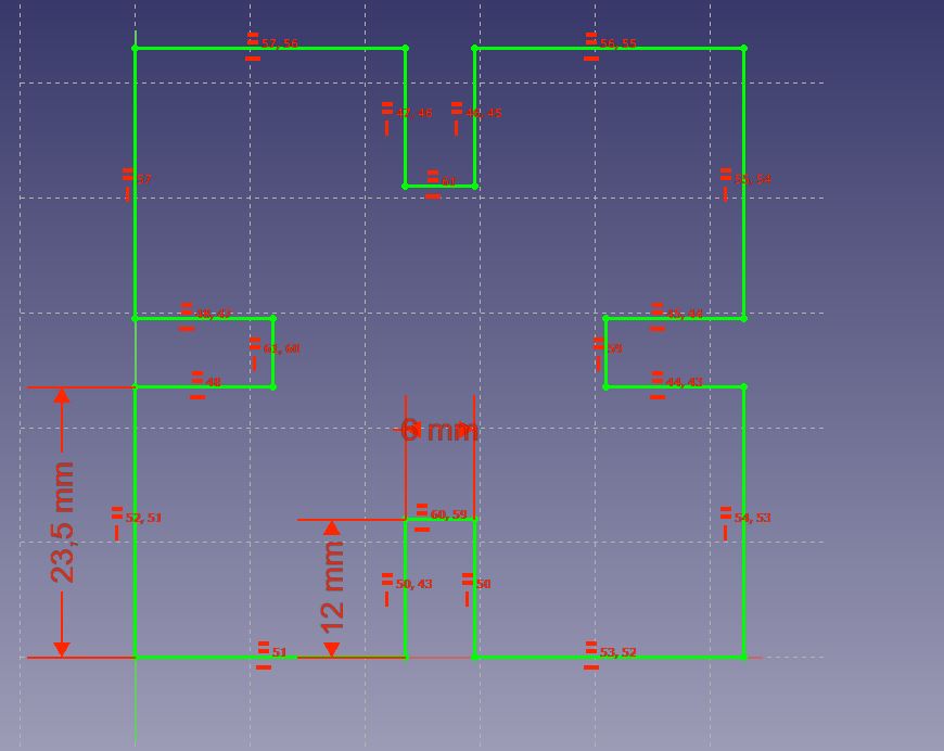
the final parameterized part.
The first sketch.
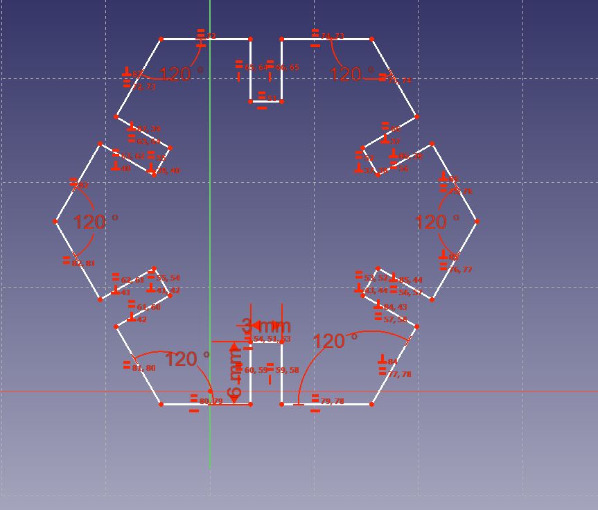
applying the restrictions, the final result.
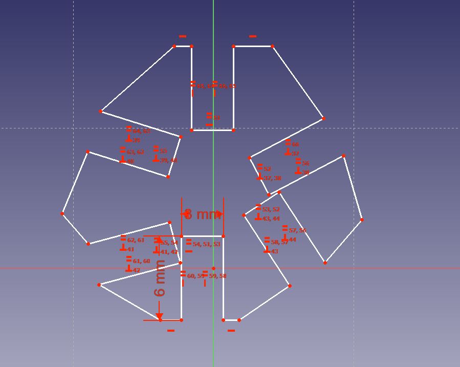
circle constraints in detail.
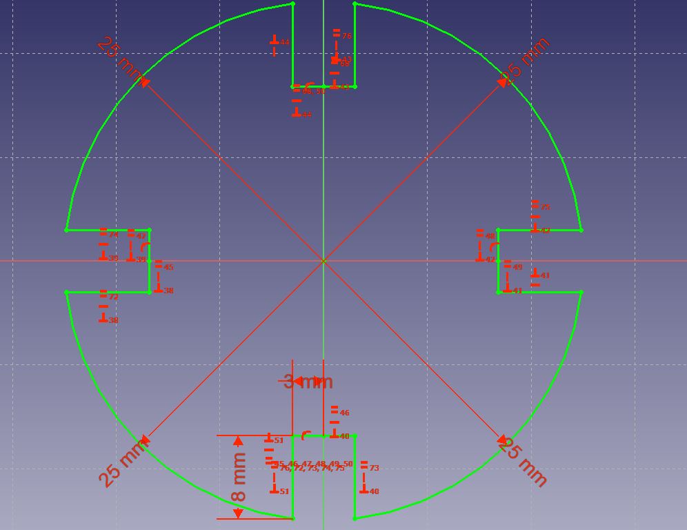
The final circle.
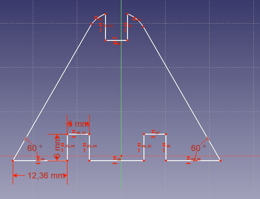
The triangle.
This is a video where you see how I linked a spreadsheet with parameters to the dimensions of several pieces and when changing the value of the worksheets these pieces are updated by changing their values.
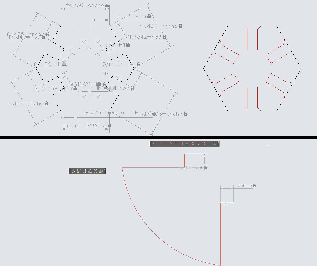
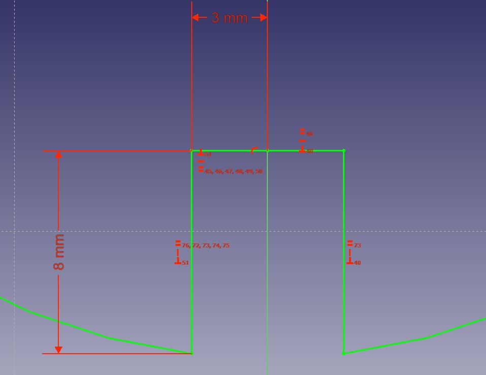
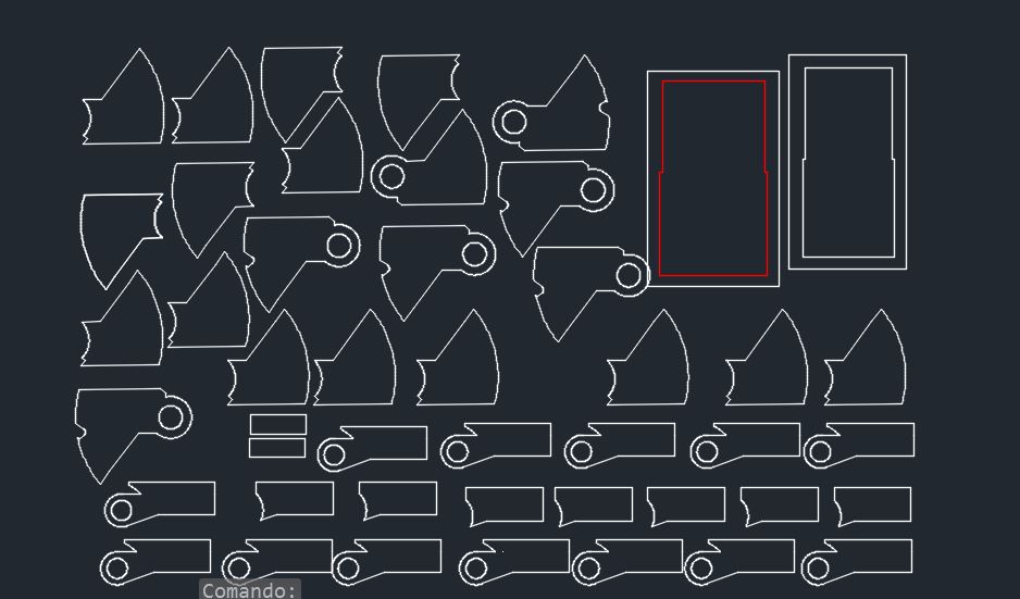
Once I had the parametric design done, I exported it to dxf with the size of pieces of my choice, the width and the desired Kerf, I drew the letters and made some chamfers in the edges.
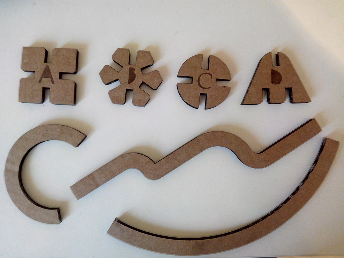
So I made and designed the triangle, the square, the circle and the hexagon, rounded some vertices, made chamfers in the entrances of the socket so that they could fit more easily.
This is the design of the parts.
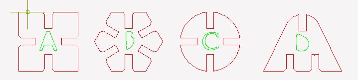
My four parts.
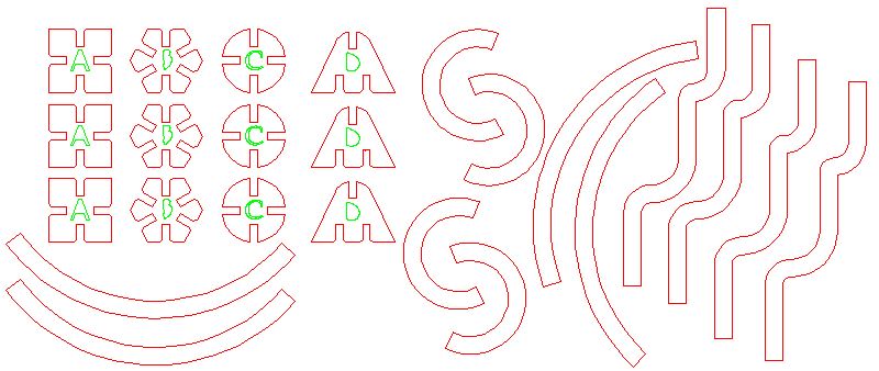
To save material I have put the pieces as close as possible.
So they were once cut.
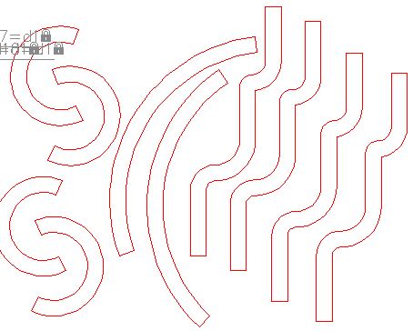
I also made other auxiliary and elongated pieces for other purposes.
Parameters:
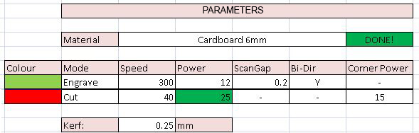
Cut and engrave parameters.
The kerf is the amount of material burned with the laser cut, in this case for 6mm cardboard, the kerf is 0.25mm we have to add to each side of the piece to fit well: Calculated with templates.I separated and ordered the pieces and started playing with them.
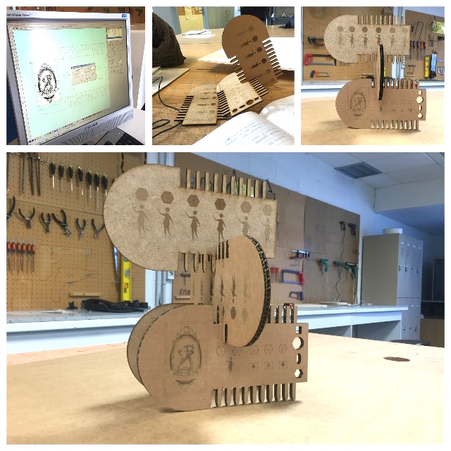
The truth is that I was surprised how many possibilities it has, it soon occurred to me to make a stand with pens.
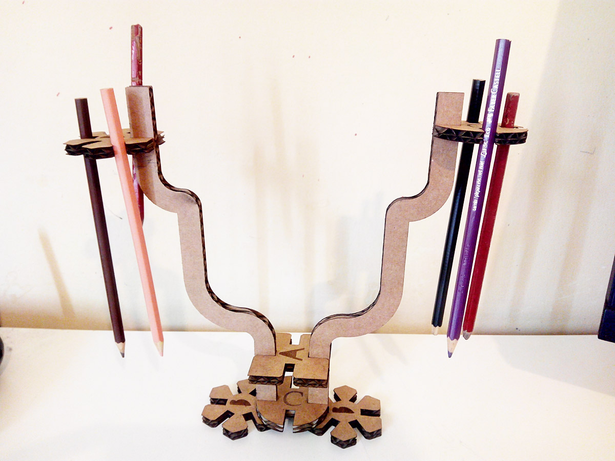
My stand
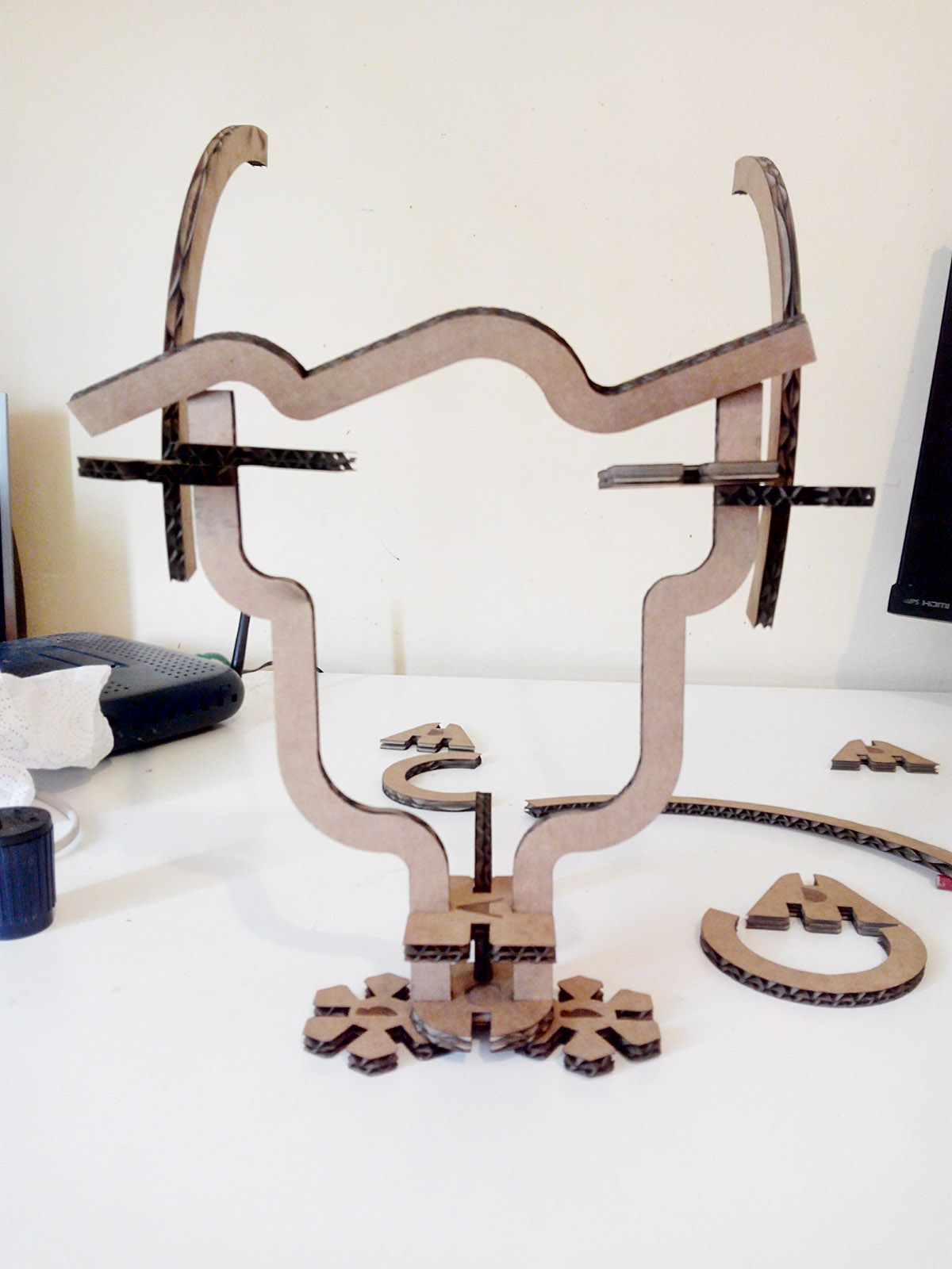
A kind of face with horns
I also took out my old hobbies and built a fortress for my old friends.
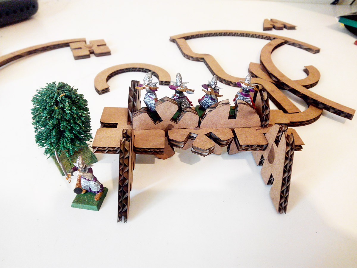
A fortress.
At that time I would have needed a pressfit.
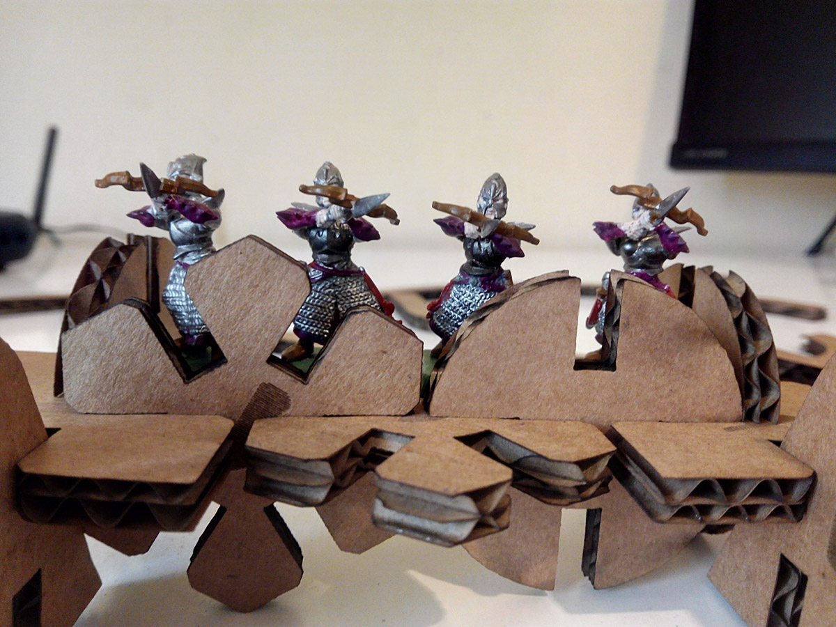
A million of posibilities.
Failures:
in some pieces I have not taken into account the central distance so that you can fit two pieces at a time, I happen to the circles, which given their size in the central part can not fit 2 of these.
This error can be solved by making the union of 6 mm smaller or the piece itself is larger and the union maintains the dimensions.
Laser Cutting Machine in Final Project:
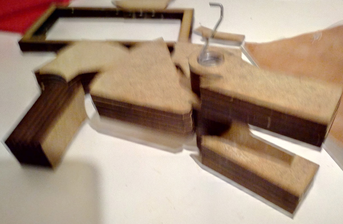
For the final project I used the laser cutting machine to make a prototype quickly.
I made a 3D modeling that I then sliced into 2D and then I sinced with glue.
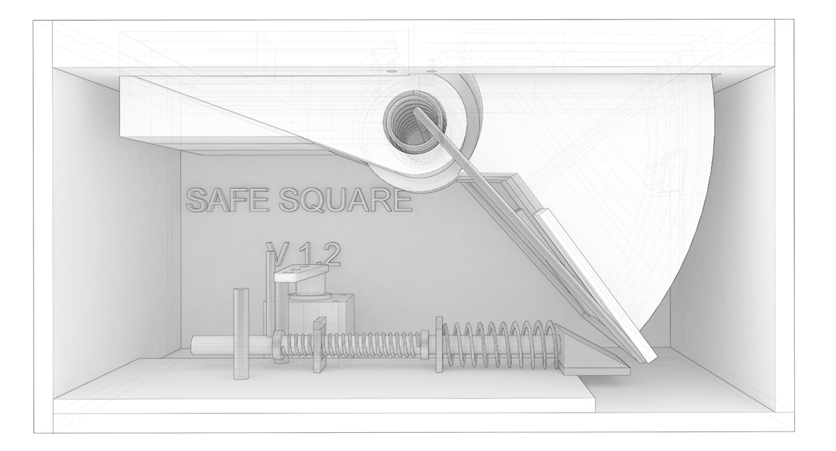
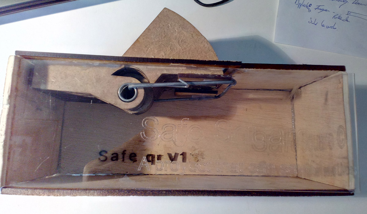
V1.2 of my project (prototype).
I decided to make a quick prototype of the version 1.2 using the laser cutting machine
 Parameters:
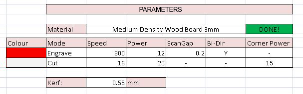
Cut and engrave parameters for Md wood board 3mm.
And this is how the prototype works mechanically.
For more information click in this button.
Files:
templatea
templateb
Raccoons 1 and 2
dxf of pressfit
File in Freecad