

Week 15 - Networking and communications
![]()
![]()
Assignment:
design and build a wired &/or wireless network connecting at least two processors
![]()
![]()
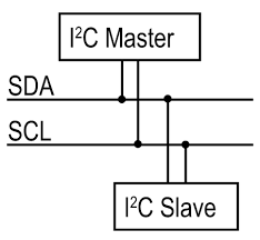
Introduction to the I2C bus
First some theory. The I2C bus, Ih square-zeh, Ei-square-Ceh or TWI (Two Wire Interface) is a small control bus. The Company Phillips invented it for communication between central control units with the surrounding interface and slave units on a circuit board. For this purpose, a comparatively slow and simple two-wire bus system has been developed, which considerably reduces the otherwise required line effort and thus makes the assembly connections clearer and simpler.
![]()
![]()
Master Writer/Slave Receiver for my Fabkit V.2
For my Final Project it is very userful to set up two (or more) Fabkit-boards to share information with each other. In this example, at first two boards are programmed to communicate with one another in a Master Writer/Slave Receiver configuration via the I2C synchronous serial protocol. Several functions of Arduino's Wire Library are used to accomplish this. Fabkit 1, the Master, is programmed to send 6 bytes of data every half second to a uniquely addressed Slave. Once that message is received, it can then be viewed in the Slave board's serial monitor window opened on the USB connected computer running the Arduino Software (IDE).
The I2C protocol involves using two lines to send and receive data: a serial clock pin (SCL) that the Fabkit Master board pulses at a regular interval, and a serial data pin (SDA) over which data is sent between the two devices. As the clock line changes from low to high (known as the rising edge of the clock pulse), a single bit of information - that will form in sequence the address of a specific device and a a command or data - is transferred from the board to the I2C device over the SDA line. When this information is sent - bit after bit -, the called upon device executes the request and transmits it's data back - if required - to the board over the same line using the clock signal still generated by the Master on SCL as timing. The initial eight bits (i.e. eight clock pulses) from the Master to Slaves contain the address of the device the Master wants data from. The bits after contain the memory address on the Slave that the Master wants to read data from or write data to, and the data to be written.
Each Slave device has to have its own unique address and both master and slave devices need to take turns communicating over a the same data line line. In this way, it's possible for your fabkit or satshakit boards to communicate with many device or other boards using just two pins of your microcontroller, using each device's unique address.![]()
![]()
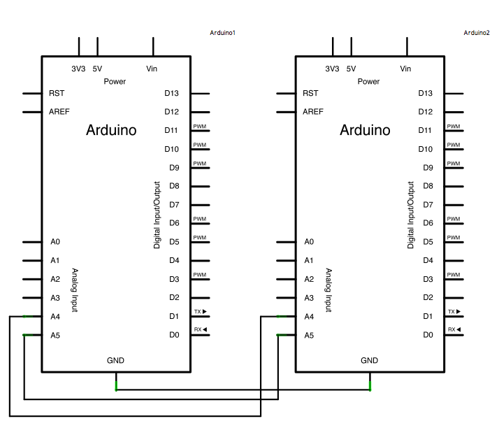
The following graphic shows the Arduino schematic for 1 Master and 1 Slave:
![]()
![]()
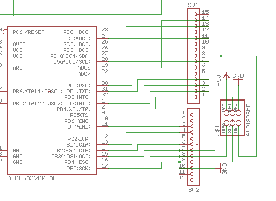
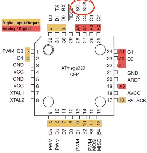
Again transform the Arduino pinouts to ATmega328P pinouts with the help of the following graphic (CLK = SCL/PC5; DATA = SDA/PC4):

![]()
![]()
CLK = SCL/PC5; DATA = SDA/PC4:
![]()

![]()
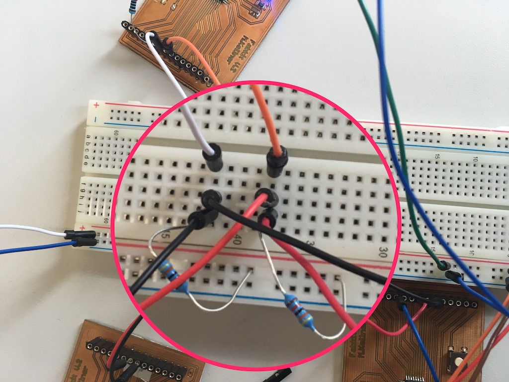
Required hardware for this assignment:
![]()
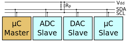
The following diagram shows three devices. I²C requires two signal lines: clock (SCL = signal clock) and data line (SDA = signal data). Both are connected to the pull-up resistors RP at the supply voltage VDD:
![]()
![]()
![]()
![]()
![]()
Video1: I2C - 1 Master, 1 Slave LED Blink example
![]()
![]()
![]()
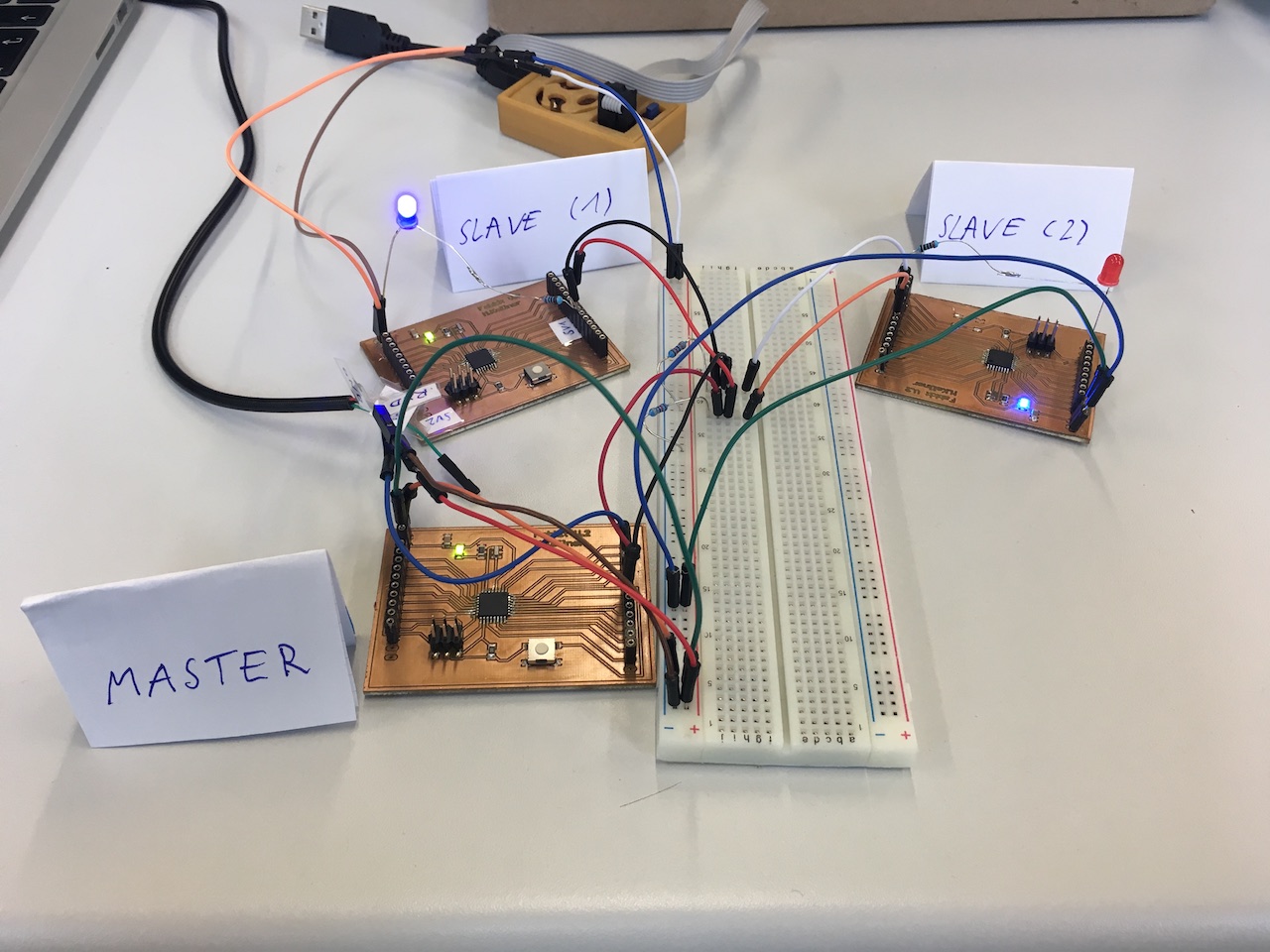
Video2: I2C - 1 Master, 2 Slave LED Blink example
![]()
![]()
![]()
![]()
Sketch for the Master Fabkit
// Wire Master LED Writer

// Writes data to an I2C slave device


#include <Wire.h>

void setup() {
  Wire.begin(); // join i2c bus (address optional for master)
}

void loop() {
  Wire.beginTransmission(8); // transmit to device #8
  Wire.write(1);              // sends one byte
  Wire.endTransmission();    // stop transmitting

  Wire.beginTransmission(9); // transmit to device #9
  Wire.write(0);              // sends one byte
  Wire.endTransmission();    // stop transmitting

  delay(500);

   Wire.beginTransmission(8); // transmit to device #8
  Wire.write(0);              // sends one byte
  Wire.endTransmission();    // stop transmitting

  Wire.beginTransmission(9); // transmit to device #9
  Wire.write(1);              // sends one byte
  Wire.endTransmission();    // stop transmitting

  delay(500);


 }
![]()
Sketch for the first slave Fabkit
// Wire Slave LED Receiver


#include <Wire.h>

void setup() {
  pinMode(A3, OUTPUT);
  Wire.begin(8);                // join i2c bus with address #8
  Wire.onReceive(receiveEvent); // register event
}

void loop() {
  delay(100);
}

// function that executes whenever data is received from master
// this function is registered as an event, see setup()
void receiveEvent(int howMany) {

  int x = Wire.read();    // receive byte as an integer
  if (x == 0)
    digitalWrite(A3, HIGH);
  else
    digitalWrite(A3, LOW);
}
![]()
Sketch for the second slave Fabkit
// Wire Slave LED Receiver

#include <Wire.h>

void setup() {
  pinMode(A3, OUTPUT);
  Wire.begin(9);                // join i2c bus with address #9
  Wire.onReceive(receiveEvent); // register event
}

void loop() {
  delay(100);
}

// function that executes whenever data is received from master
// this function is registered as an event, see setup()
void receiveEvent(int howMany) {

  int x = Wire.read();    // receive byte as an integer
  if (x == 0)
    digitalWrite(A3, HIGH);
  else
    digitalWrite(A3, LOW);
}
![]()
![]()
Download-Section:
i2c-master-sketch
ic2-slave1-sketch
ic2-slave2-sketch
Download the Fabkit Version 2 (with ISP-header)
on my Week 10 - Output device download section.
Source:
I would like to refer to page Arduino.cc, Wikipedia and www.hlembke.de which has helped me very much to get the necessary information.
![]()
![]()