

Week 10 - Machine design Output Devices
![]()
![]()
![]()
Assignment
![]()
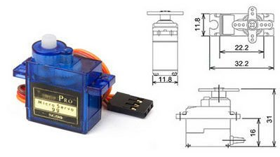
Datasheet for micro serco motor 9G SG90: Klick here
![]()
![]()
![]()
Make a fabkit board
- In order to be able to use all the devices and not have to build a new board every time, we decided to build a fabkit board.
![]()
![]()
Think about a Output Device for final project
- I have really thought and researched for a long time. What could I use here for my final project?, a fan?, a pump?
After some time I suddenly hit the Neopixel LEDs from adafruit and found this system very interesting.
![]()
Link to Adafruit Neopixels
Link to Adafruit-NeoPixel-Ring
![]()
![]()
I am very interessted to build the neopixels. Other possibilities would be as already mentioned
a pump or possibly a fan in order to keep the plants in motion and to ensure fresh air supply. I've always wanted to have my own development board like a Raspberry or Arduino. Of course, is a self-styled like the fabkit board or a satshakit even cooler.
![]()
Neopixelboardmodul first trys:
![]()
Unfortunately I have found that I do not find it in this vertical way not particularly good.
I had problems when designing the pcb. I will (if I use LEDs as output) create smaller modular elements. But to practice a little with eagle it was not a waste of time.
![]()
![]()
![]()
Fabkit-board development:
![]()
![]()
![]()
![]()
![]()
![]()
![]()
![]()
![]()
![]()
![]()
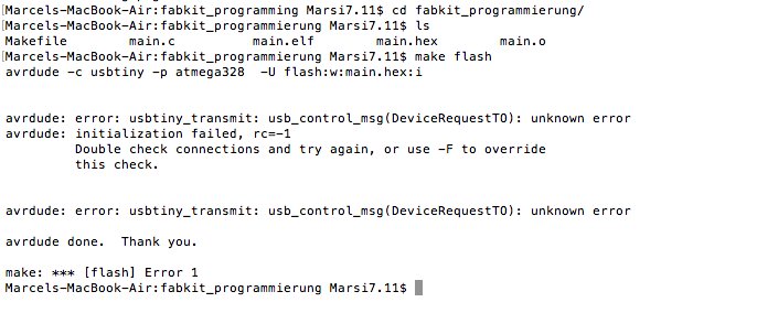
Flash the ATmega with a example programm
To check the function of the board I have first changed the makefile and the main.c file from the embedded programing week (week 8) to bring the LED blinking.
![]()
![]()
![]()
![]()
![]()
Add a Micro Servo Motor 9G SG90 to the Fabkit
Ok here starts the actual output device doku. After I thought about the neopixel, I have rejected this idea, since I would like to use a different lighting for the final project.
![]()
![]()
1. Open the Arduino preference window and add the following URL to the "Additional Board Manager" URL´s list:
![]()
![]()
2. Now go to "Tools" -> "Board" -> "Board Manager" and look for "Barebones ATmega Chips" and install it (latest version). After you done this, a new section called ATmega Microcontrollers. Now I choose the ATmega328/328P. As Processor I choose "ATmega328" as well and set the clock to 16 MHz (external).
![]()
3. Lastly the bootloader needs to be burn. The bootloader is the start program for the chip. Go to "Tools" -> "Burn Bootloader".
![]()
![]()
![]()
![]()
![]()
![]()
![]()
![]()
![]()
![]()
Fabkit V 1 Servo test:
![]()
![]()
![]()
Making another Fabkit (my Fabkit V.2)
![]()
![]()
![]()

![]()
![]()
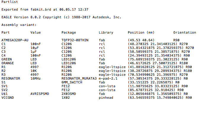
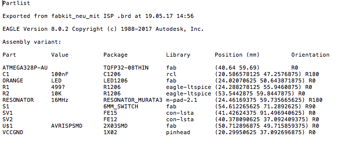
This time I use only 1 Capacitor (100 N) and 2 Resistors (10KΩ and 470Ω)
![]()
Patlist exported from eagle:
![]()
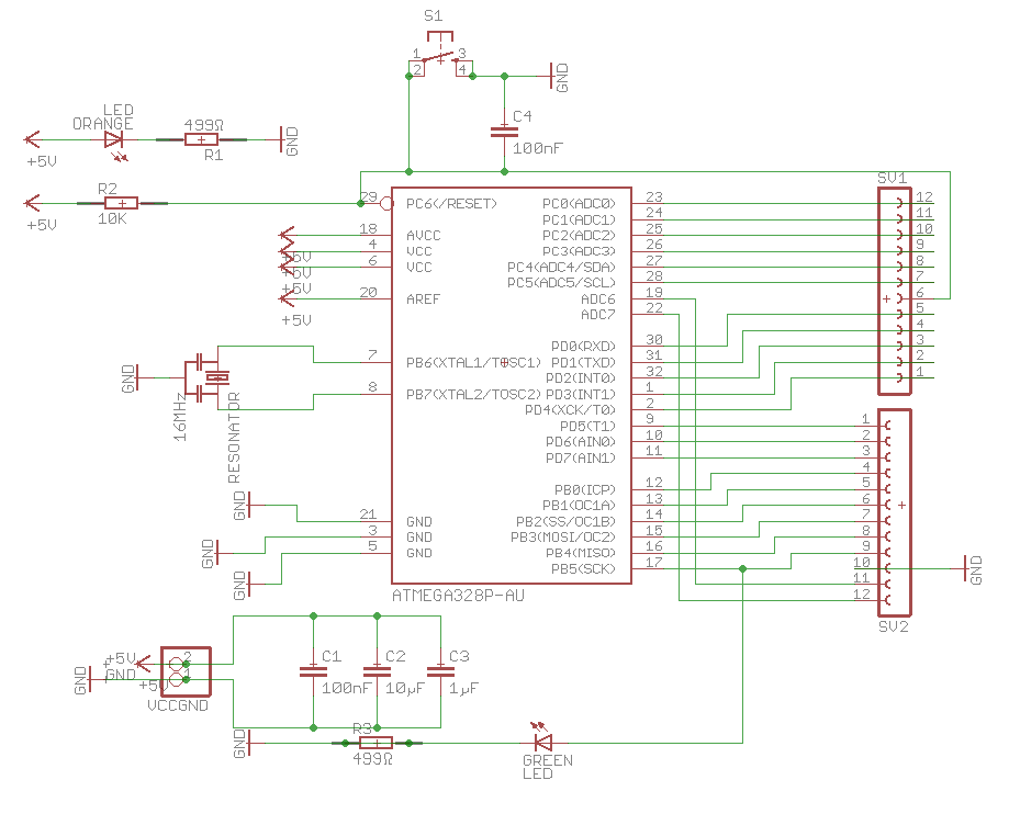
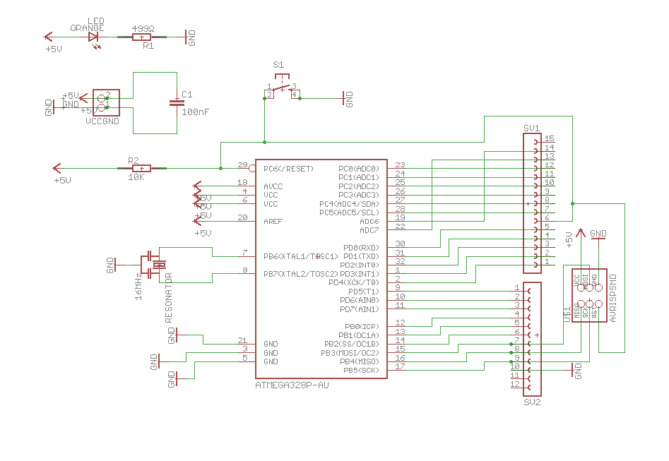
Schematic in eagle:
![]()
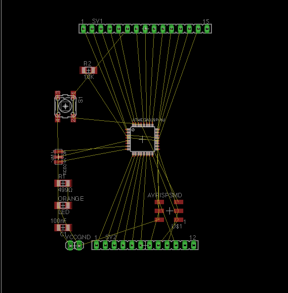
Layouting in eagle:
![]()
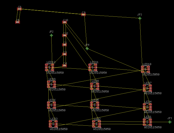
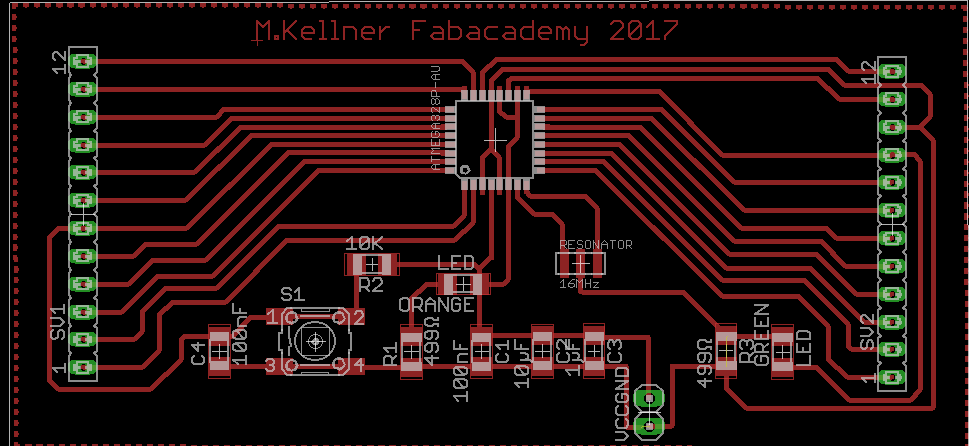
Board Layout from eagle:

![]()
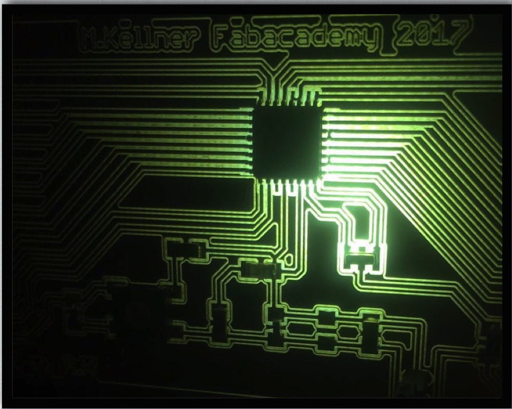
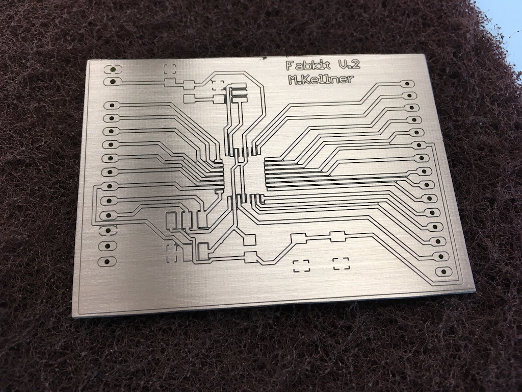
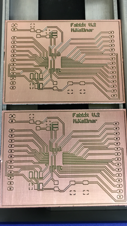
Milled and polished pcb:
![]()
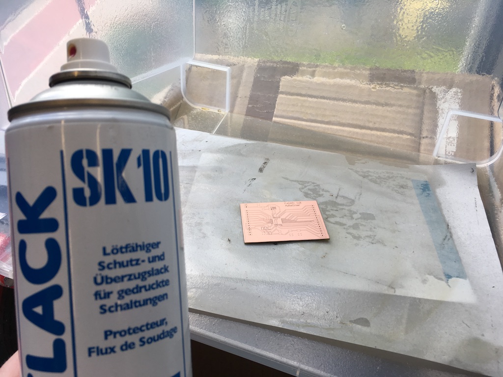
Lacquered pcb with solder-lacquer:
![]()
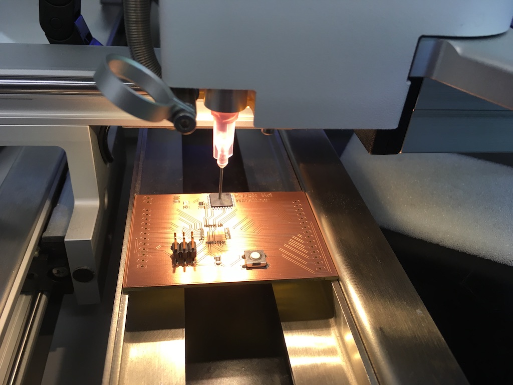
Place the components with the pick and place machine from LPKF:
![]()
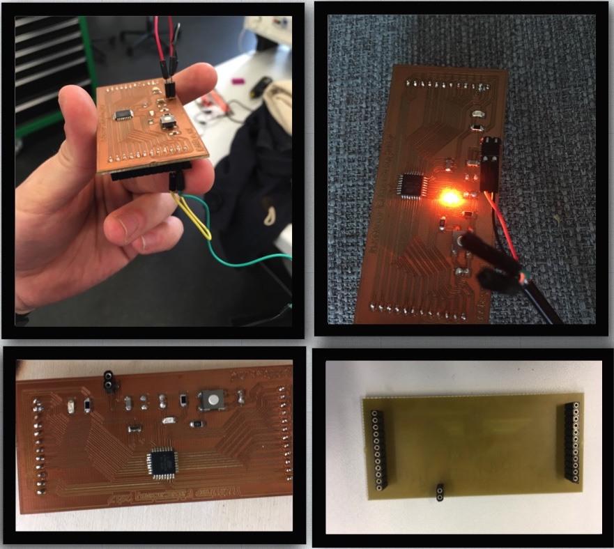
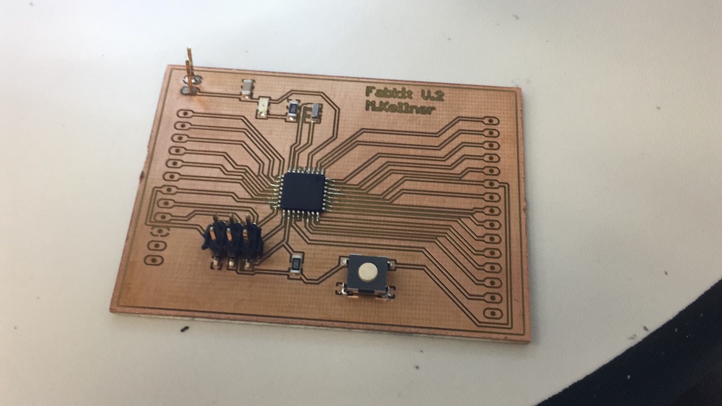
Ready equiped pcb-board (without pin-header sv1 and sv2):
![]()
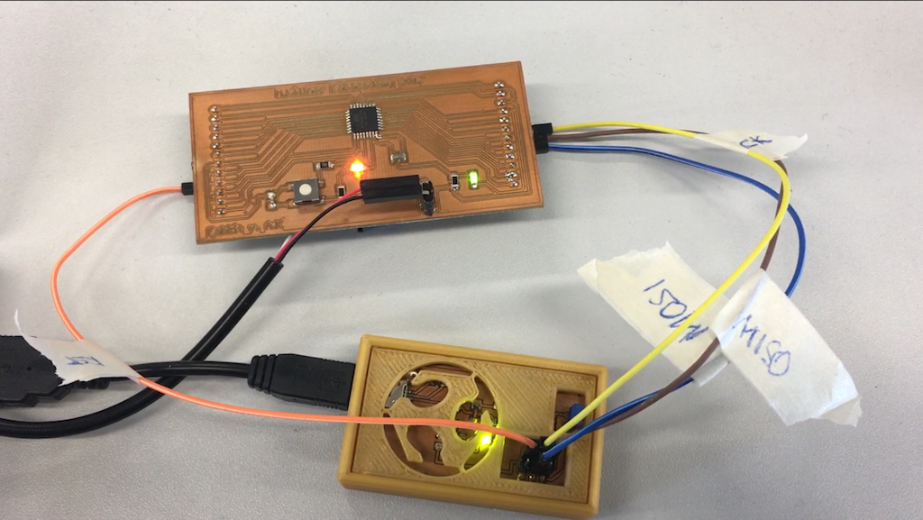
Programming the board:
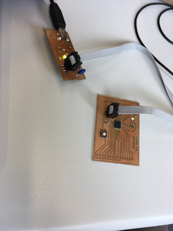
![]()
Making a second baord:
![]()
To check these steps again in more detail check out my Week 4 - electronics production assignment.
![]()
![]()
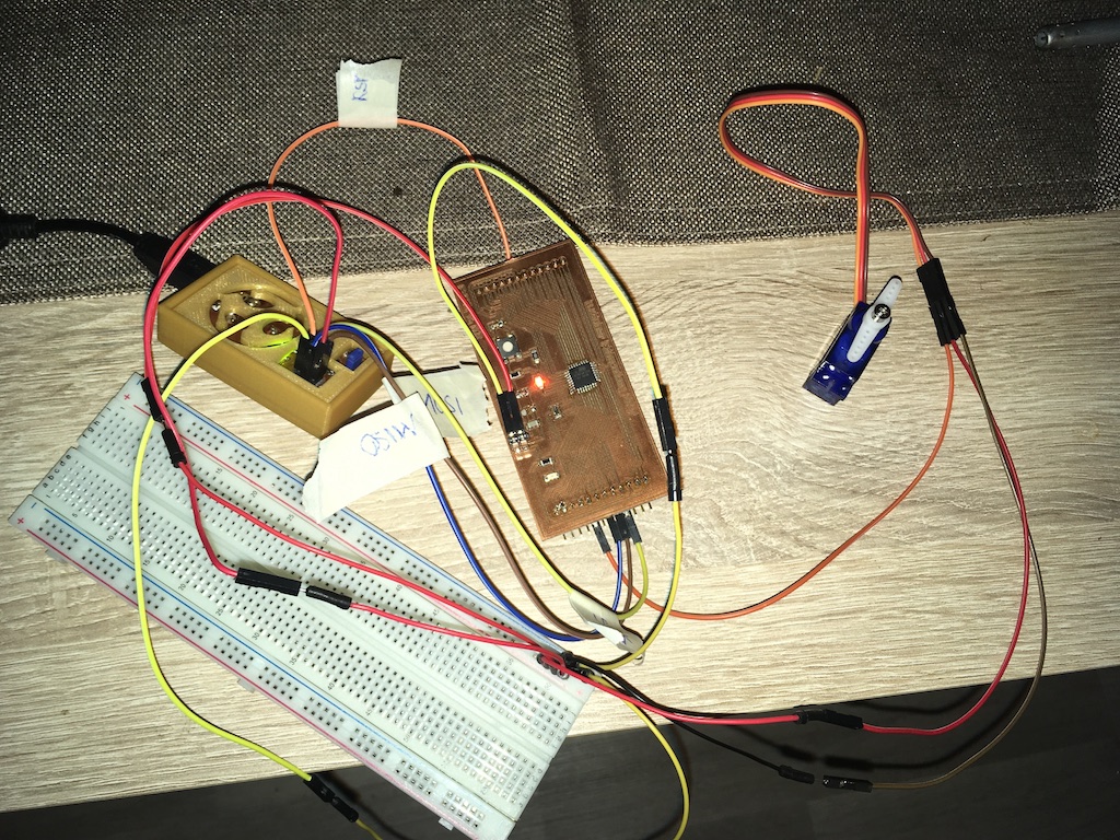
Fabkit V 2 Servo test:
![]()
Sketch for the Servo-test:
#include < Servo.h >

Servo myservo;  // create servo object to control a servo
// twelve servo objects can be created on most boards

int pos = 0;    // variable to store the servo position

void setup() {
  myservo.attach(9);  // attaches the servo on pin 9 to the servo object
}

void loop() {
  for (pos = 0; pos <= 180; pos += 1) { // goes from 0 degrees to 180 degrees
    // in steps of 1 degree
    myservo.write(pos);              // tell servo to go to position in variable 'pos'
    delay(15);                       // waits 15ms for the servo to reach the position
  }
  for (pos = 180; pos >= 0; pos -= 1) { // goes from 180 degrees to 0 degrees
    myservo.write(pos);              // tell servo to go to position in variable 'pos'
    delay(15);                       // waits 15ms for the servo to reach the position
  }
}
![]()
![]()
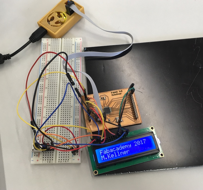
Connect an LCD display
At the end I have connected an LCD display and output the text "Fabacademy 2017 M.Kellner". For this I used the Liquid Chrystal Lib. The datasheet of the lc display of type 1602a can be found here
![]()
Sketch for the LC-Display:
#include  //load LCD-Bibliothek

LiquidCrystal lcd(12, 11, 5, 4, 3, 2); //This line determines which pins of the microcontroller board are used for the LCD.

void setup()
{
lcd.begin(16, 2); //Setup shows how many characters and lines are used. Here: 16 characters in 2 lines.
}

void loop()
{
lcd.setCursor(0, 0); //Set the start position of the display on the LCD. Lcd.setCursor (0,0) means: First character in the first line.
lcd.print("Fabacademy 2017");
lcd.setCursor(0, 1); // lcd.setCursor(0,1) Means: First character in the second line.
lcd.print("M.Kellner");
}
![]()
Postscript/Additions:
![]()
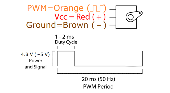
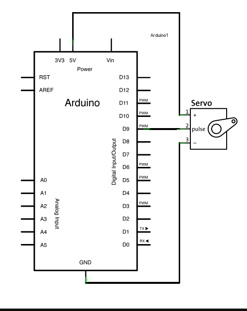
For the servo to work you need to connect it to a pin which has pwm enabled or create a code that is able to switch a pin in the frequency required by the servo. Thats why pin 9 is used, the servo library can work on these pins. Explain the pin connections for the servo and the LCD. and what the code does:
A servo was controlled with a selfmade microcontroller. Now I need to explain the pin connections for the servo.
![]()
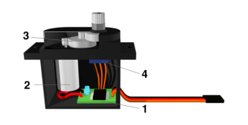
Servo: Construction and connection A servo consists of a motor control unit (1), an electric motor (2), a gearbox (3) and a potentiometer for position determination (4). All components are housed in a robust housing.
![]()
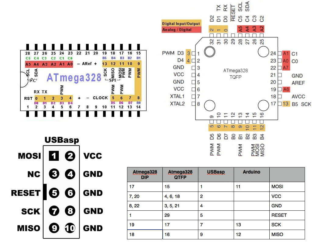
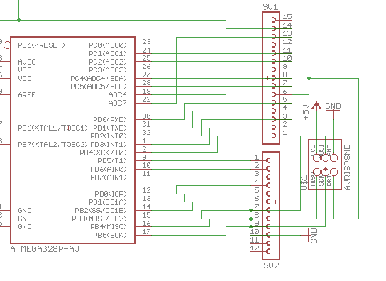
On the following sketch you can see the wiring with an Arduino. Here I transform the pins again to my ATmega328 P-AU with help of my transformation-sheet

![]()
![]()
![]()

![]()
What is PWM?
The pulse width modulation (PWM) is a modulation type in which a technical variable (eg, electrical voltage) is applied to the pulse width. It Changes between two values. At a constant frequency, the duty cycle of a square pulse is modulated, thats the width of the pulses forming it.
In pulse width modulation, a square-wave signal with a fixed frequency is taken and the width of the respective pulses is varied. It is best explained by a graphic:
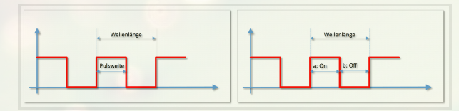
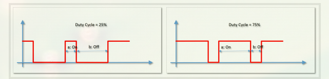
The distance between two successive pulses is called the period duration, the width of the active pulse (a) is the pulse width. The average voltage applied to this pin is given by the ratio of a to (a + b). If a is only half as wide as the period duration, then I have only 50% of the signal voltage available on average. This ratio of pulse width to period duration is also referred to as the "duty cycle" (the time in which the pin is "in service"). As a graphic, this looks like this:
This pulse wave modulation can be used to control servos. Here, the small microcontroller of the servo interprets the pulse width as a winch for the servo arm. So you can simply put the three cables from a servo to plus and ground and the signal cable to a PWM pin and the servo rotates between 0 and 180 degrees depending on the value we write with myservo.Write.
![]()
To control the servo with my fabkit, it is best to use the servo library Servo.h. It is already included in the Arduino software. The library is integrated at the start of the program:
#include < Servo.h >
A servo object must then be created:
Servo myservo;
In the setup method, the servo is commanded:
myservo.attach (9);
initialized. The number in the brackets indicates the digital pin of the Arduino to which the servo is connected. The servo can now be very easy from the loop method with:
myservo.write(Position);
To a certain angle. The angle (0 - 180 °) is indicated in brackets.
![]()
The setup() function is called when a sketch starts. Use it to initialize variables, pin modes, start using libraries, etc. The setup function will only run once, after each powerup or reset of the board.
void setup()
After creating a setup() function, which initializes and sets the initial values, the loop() function loops consecutively, allowing your program to change and respond. Use it to actively control the board.
void loop()
Here is the Sketch I was using for my fabkit (its an example sketch from the Arduiono ide called sweep):
#include < Servo.h > // load the servo library of the arduino ide

Servo myservo;  // create servo object to control a servo


int pos = 0;    // variable for the servo position

void setup() {
  myservo.attach(9);  // attaches the servo on pin 13/PWM B1/9 to the servo object. That is pin 5 on SV2 on my Fabkit.
}

void loop() {
  for (pos = 0; pos <= 180; pos += 1) {  // The Servo can go from 0 degrees to 180 degrees
    // in steps of 1 degree
    myservo.write(pos);              // tell servo to go to position in variable 'pos'
    delay(15);                       // waits 15ms for the servo to reach the position
  }
  for (pos = 180; pos >= 0; pos -= 1) { // goes from 180 degrees to 0 degrees
    myservo.write(pos);              // tell servo to go to position in variable 'pos'
    delay(15);                       // waits 15ms for the servo to reach the position.
  }
}
![]()
![]()
Explain the lcd wiring and code:
A lcd was controlled with a selfmade microcontroller. Now I need to explain the pin connections for the servo:
Again I transform all the Arduino pins to my selfmade fabkit with the illustration Above:

The rotary control is used to adjust the contrast of the LCD. The LED backlight is supplied with 5V as shown in the sketch. Since the label on the LCD would not be recognized in the sketch, it is not shown.
In the program, the library, which by the way is delivered with the Arduino software, is integrated:
#include LiquidCrystal theDisplay(12, 11, 5, 4, 3, 2);
Now the LiquidCrystal object is created with the name lcd. The digital output pins that have been used are given as parameters:
LiquidCrystal lcd(12, 11, 5, 4, 3, 2);
The display configuration is transferred in the setup. The two parameters represent the character number of a line and the number of lines. In this example, 16 characters and 2 lines:
lcd.begin(16, 2);
With print, messages can be written to the display:
lcd.print("Fabacademy 2017");
The setCursor command specifies the character to be displayed in the line and the line in which the text is to be output:
lcd.setCursor(0, 1);
With print, messages can be written to the display again:
lcd.print("M.Kellner");
Here is the Sketch I was using for my fabkit (its an example sketch from the Arduiono ide called liquid christal lib):
#include  //load LCD-Bibliothek

LiquidCrystal lcd(12, 11, 5, 4, 3, 2); //This line determines which pins of the microcontroller board are used for the LCD.

void setup()
{
lcd.begin(16, 2); //Setup shows how many characters and lines are used. Here: 16 characters in 2 lines.
}

void loop()
{
lcd.setCursor(0, 0); //Set the start position of the display on the LCD. Lcd.setCursor (0,0) means: First character in the first line.
lcd.print("Fabacademy 2017");
lcd.setCursor(0, 1); // lcd.setCursor(0,1) Means: First character in the second line.
lcd.print("M.Kellner");
}
![]()
![]()
![]()
![]()
![]()
![]()