Machine Buiding
Mechanical Design and Machine Design
The Concept
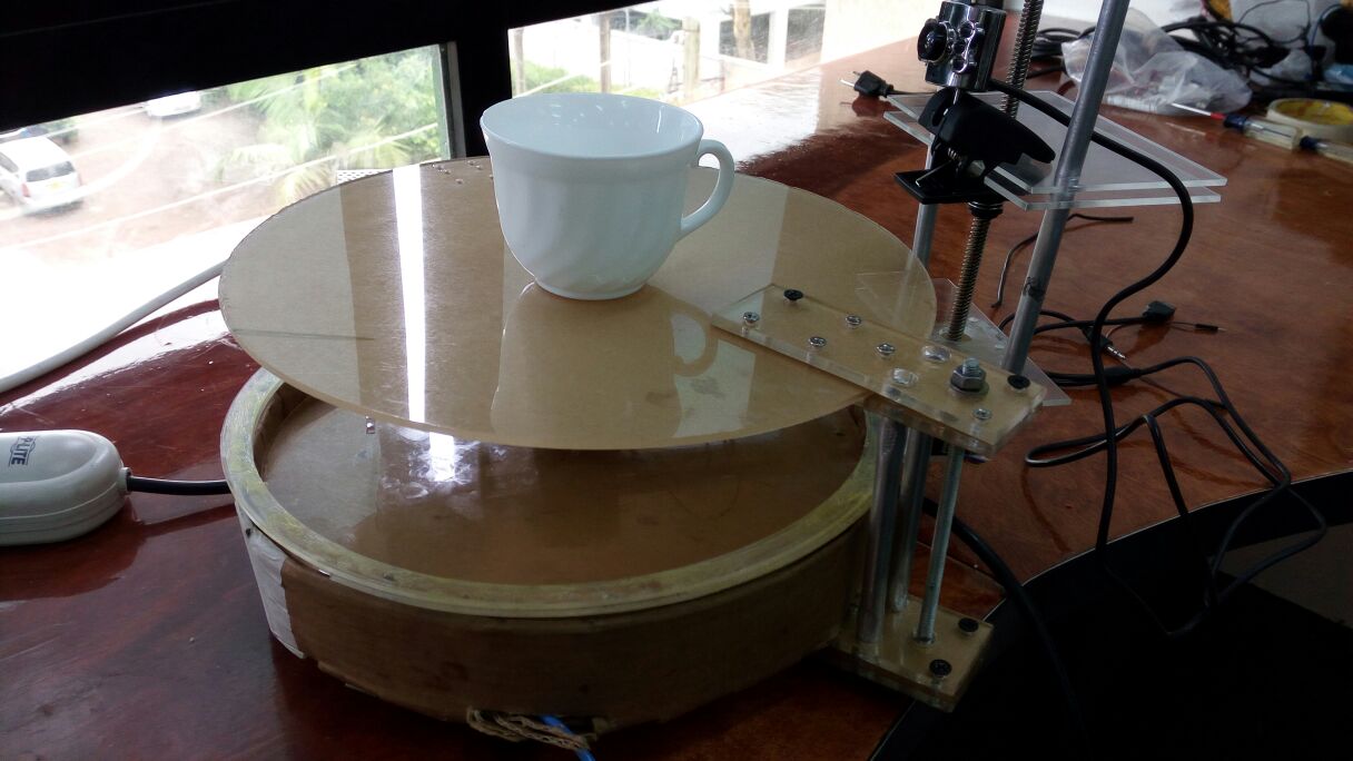
It was a hard decition to select the machine to build since we wanted to build what we can easily relate to. We then decided to build a 3D scanner. after along discussion of different suggestions floated. The 3D Scanner will like any other scanners, will be using the camera to capture images of objects which will then be stitched using Autodesk 123 catch or Reconstruct me. The Machine will have a stationed table where the object will be sitting while the Camera sitting on the rotating arm takes images all round. There are two motors used; one placed at the centre drives around the arm holding the camera while the second one which facilitates the camera's movement on the Z - axis, that is up and down.
Tools used
- Laser Cutter
- Milling and Drilling Machine
- Screw drivers
- Cutting tools (Gulotine, Scissors, Hacksaw, bandsaw among others)
- Soldering supplies
Materials used
- Soldering supplies
- Gestalt board
- Fabnet parts
- Circuit board
- Motors
- Acrylic
- Cardboard
- Alluminium rods
- Glue
- Screws
Machine Designing
The Machine Building had to combine the work in Week 9: Mechanical Design and Week 10: Machine Design
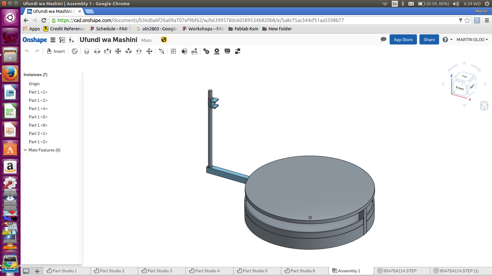
I had to use Onshape which I have been trying to perfect myself on. I had to restart the design again and again following the different suggestions which were changing each day. My team kept of bringing suggestion ranging from kind of material to be used on various parts to the the design itself.We decided to do prototype using the cardboard but with a view of making the base using metal and this would also be used for the stability of the table through the strong support running from the base.
This actually came after the fall of the first idea of making a Scanner with stationary camera while the object (to be scanned)rotates. This was due to the advice that stitching images when the Scanner/Camera is stationed is abit challenging. Read
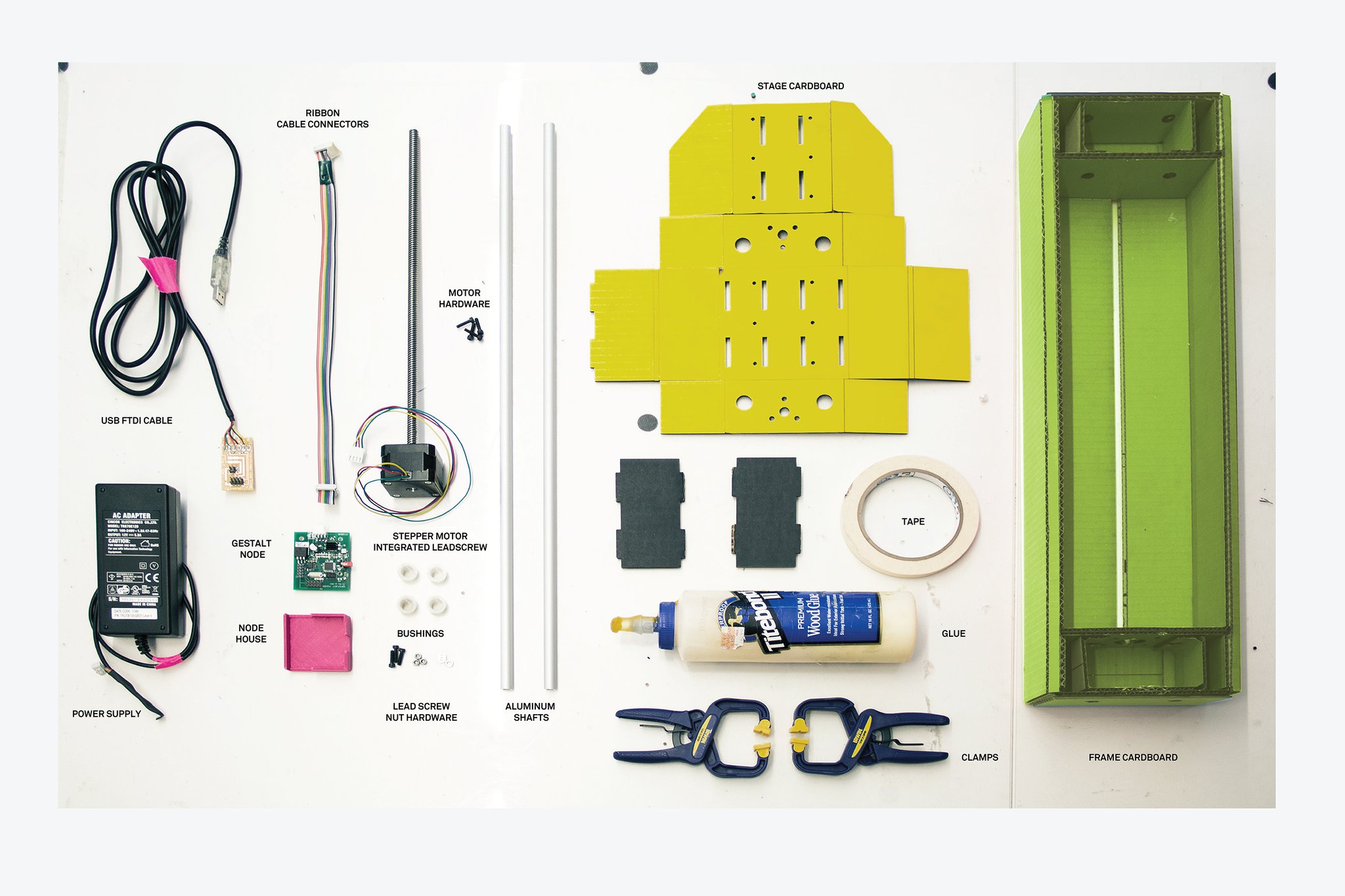
Eventually the Machine is to be built using 3 main materials; Acrylic, Cardboard and the alluminium rods apart from motors among others
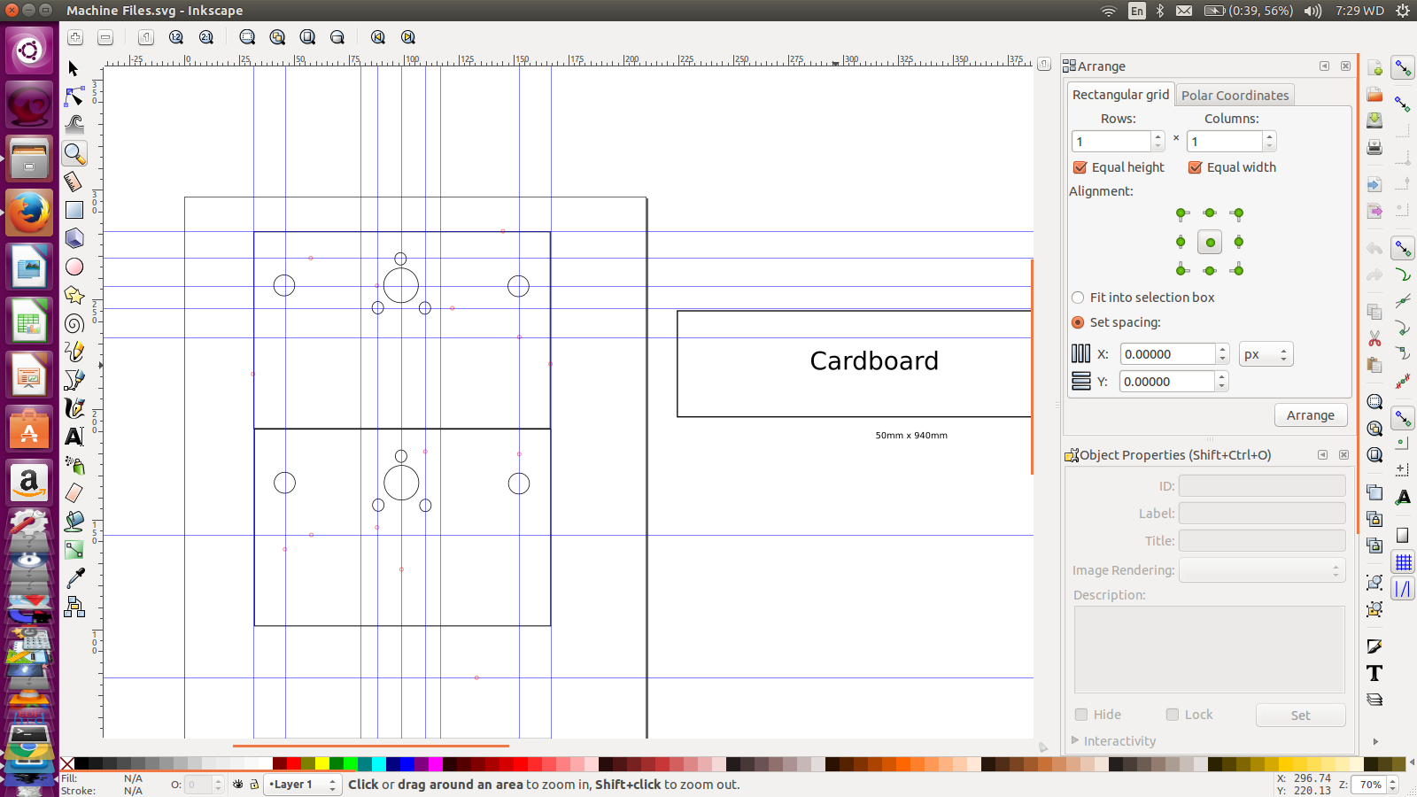
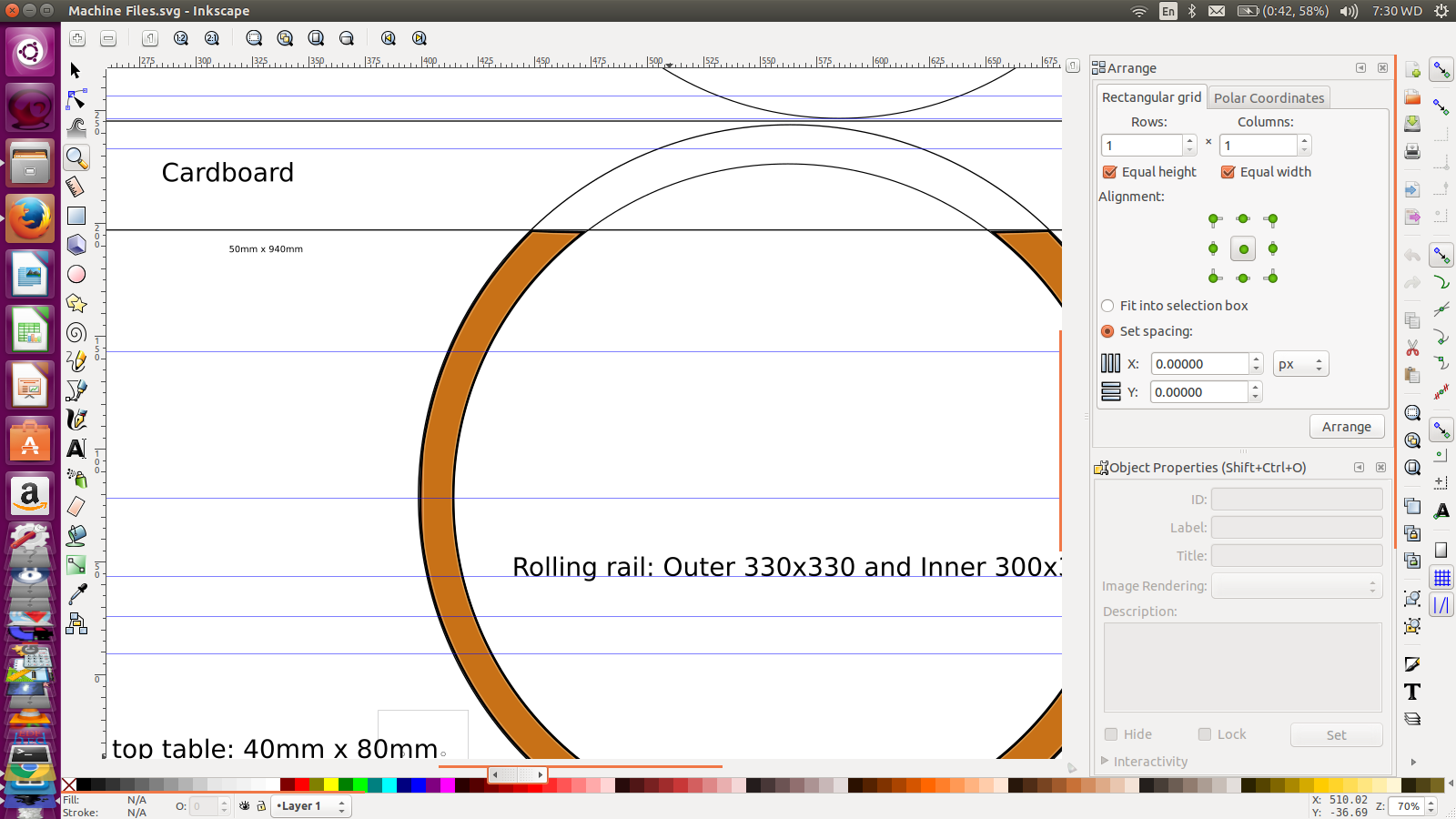
After completing my 3D Design, and we were now proceeding to laser cutting, We had to convert our files to 2D and to save ourselves from alot of trouble especially on parts which were extruded and also shelled, we opted to go for Coreldraw which also happed to work with laser software directly (Retina Full Spectrum). Alash!! My trial version just expired. I deleated it and reinstall the latest version I was using. The status remained the same.
I could not save or print anything from it so I went to Inkscape. Here, everything worked perfectly well for me and I could easily change the design whenever necessary
Laser Cutting
Here, we had to cut Cardboards and acrylic materials. Being my first direct interaction with the laser cutter, it was so interesting. I had to learn about settings of power, speed and the passes. Using two acrylic sheets with different thicknesses, help me ralise the need for material test. This automatically gives the right settings of speed and power
We did the cutting of all parts well
Machine structure Assembly
We then moved to assembly. We joined all the parts as necessary. Some of the parts which were weak got brocken in the process and had to be replaced. I returned to the laser cutter severally
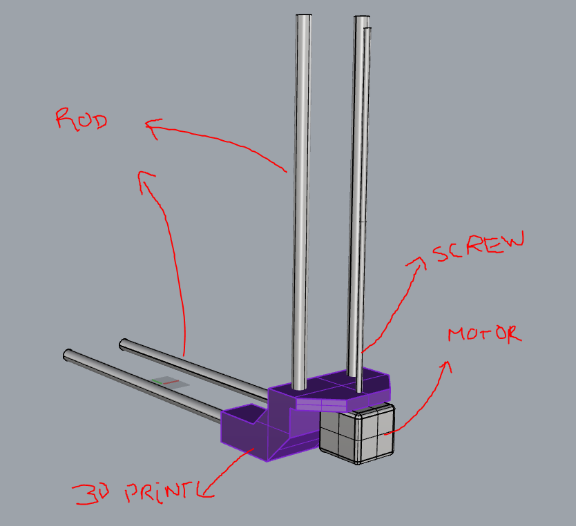
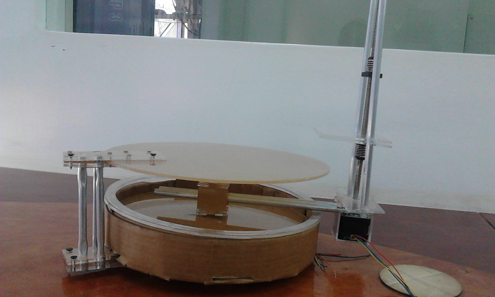
Again joining acrylic with cardboard was somehow alittle tricky but had to use clue at some point and screws at other point. Supporting the table top firmly so that it would hold scanned object in was one of the greatest challenges. We had the option of 3D printing this part but again challenge would come from our printer which normally fail and takes so many hours to print. It cannot be left to print unattended to. We decided to use the alluminium rods but letter on I decided to add a threaded rod and nuts to improve the firmness
Some of the suggestions for the 3D printing we as follow;
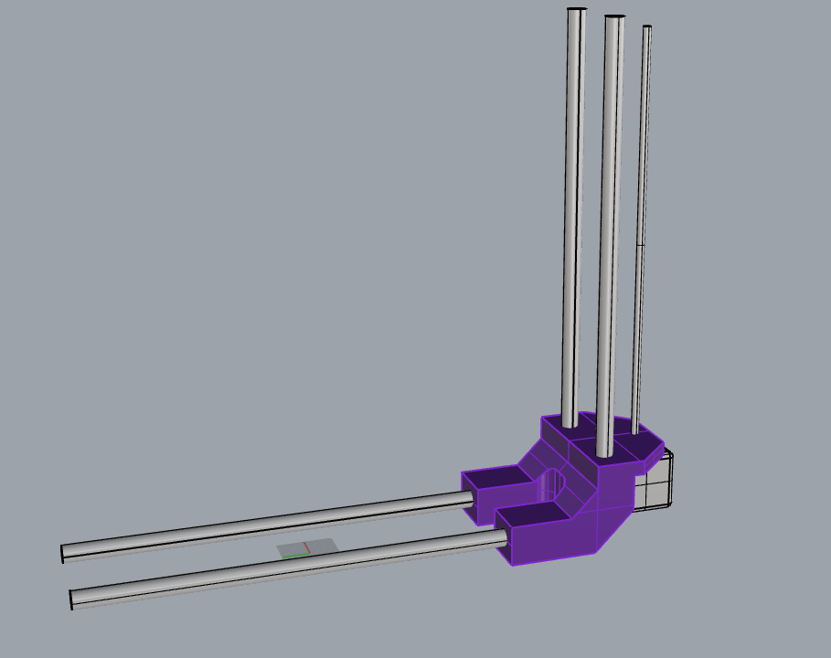
Below is the assembling of all parts into a unit
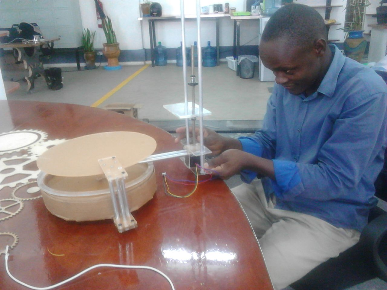
Later we realised that the weight on the rotating arm which also holds the camera was too much and had to get another weight to counter it. Thanks to fabrication skills which made us cut pieces of steel then weld them together
Electronics - Fabnet
We downloaded the Fabnet board image, milled and stuffed. This was now ready for use. This process was a bit easy being that we had milled other boards in the previous lessons.
Fabnet is a multi-drop network, i.e. multiple modules or nodes share a single set of communication wires. Each node is assigned a four-byte IP address which uniquely identifies it over the network. It also provides power at two voltages: high voltage (12V - 24V) is intended to drive motors, lamps and actuators, while low voltage (7.5V) supplies power to the logic circuits of the nodes. In Summary, Fabnet Establishes connectivity between nodes and a computer, and provides proper power which is what you need to achieve with it.
This board requires the following components:
- - High and low voltage power supplies
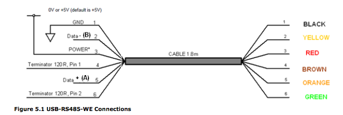
- - USB-RS485 converter cable
- - an adaptor board (076-000A) with bias resistors
Electronics - Power Supply
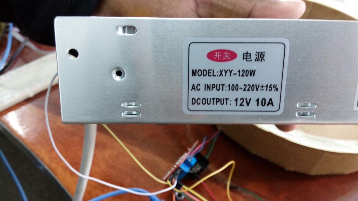
Just as explained above that Fabnet is to provide two volatages. The 12V to drive the NEMA17 Motors while the 5V to spply the board. The beauty is that it could control and separate them well. For this reason, we had to get power supply which could supply the 12V power. We bought this CCTV ower supply which worked for us perfectly
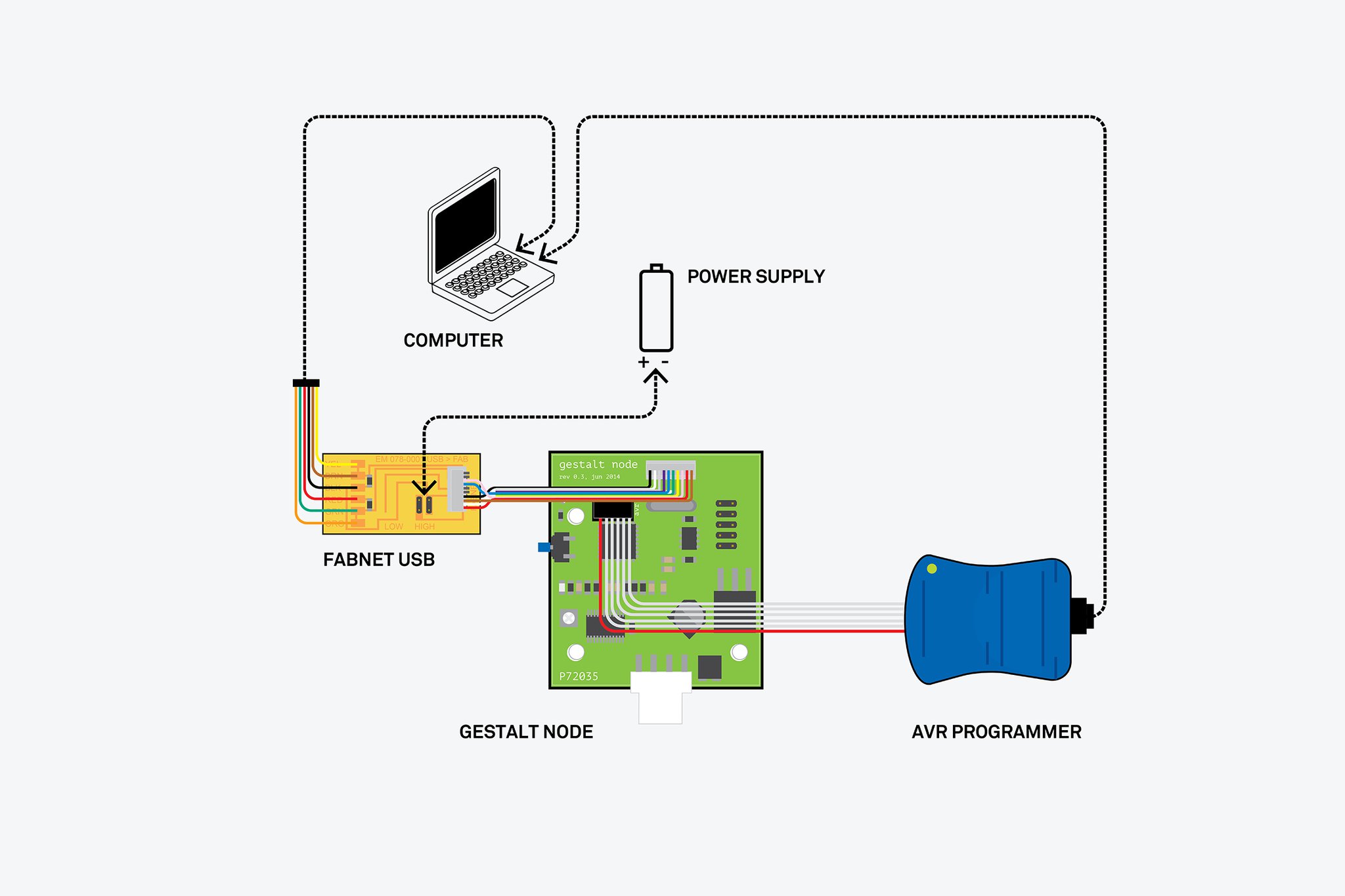
Electronics - Hooking the Node
Getting Started with the Gestalt Nodes was so easy and the board looked so simple and straight with alot of instructions already given but this turned out to be the biggest challenge. Getting the node drive the motors was not a walk in the park at all.
The components we needed to connect included;- ● The Fabnet
- ● The Gestalt Board
- ● The Power Supply
- ● The Motors &
Below were the connections procedures
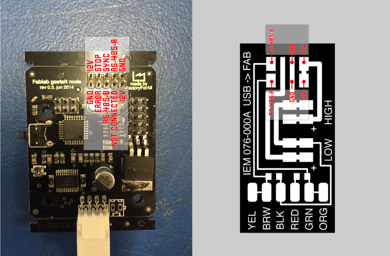
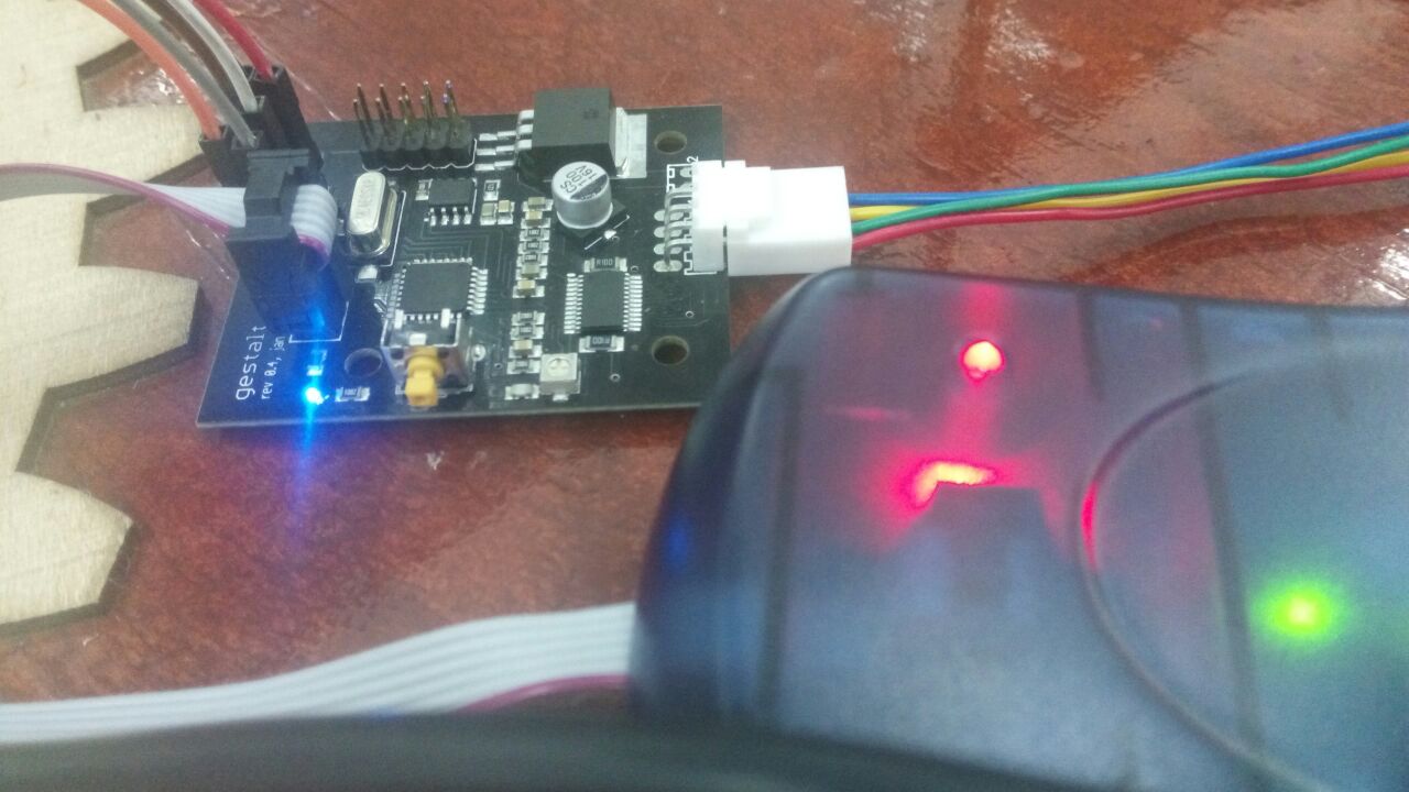
- • First, connect the Fabnet to the Gestalt Node
To get the connection, make sure that the Flat Ribbon Cabbles are the right connection with the FFC Connectors on both sides. This was done by criss-crossing some cables as shown but making sure that they correctly corespond as per the images below
Gestalt Node Failure
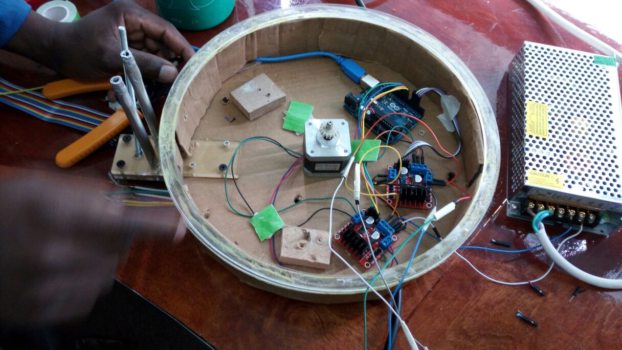
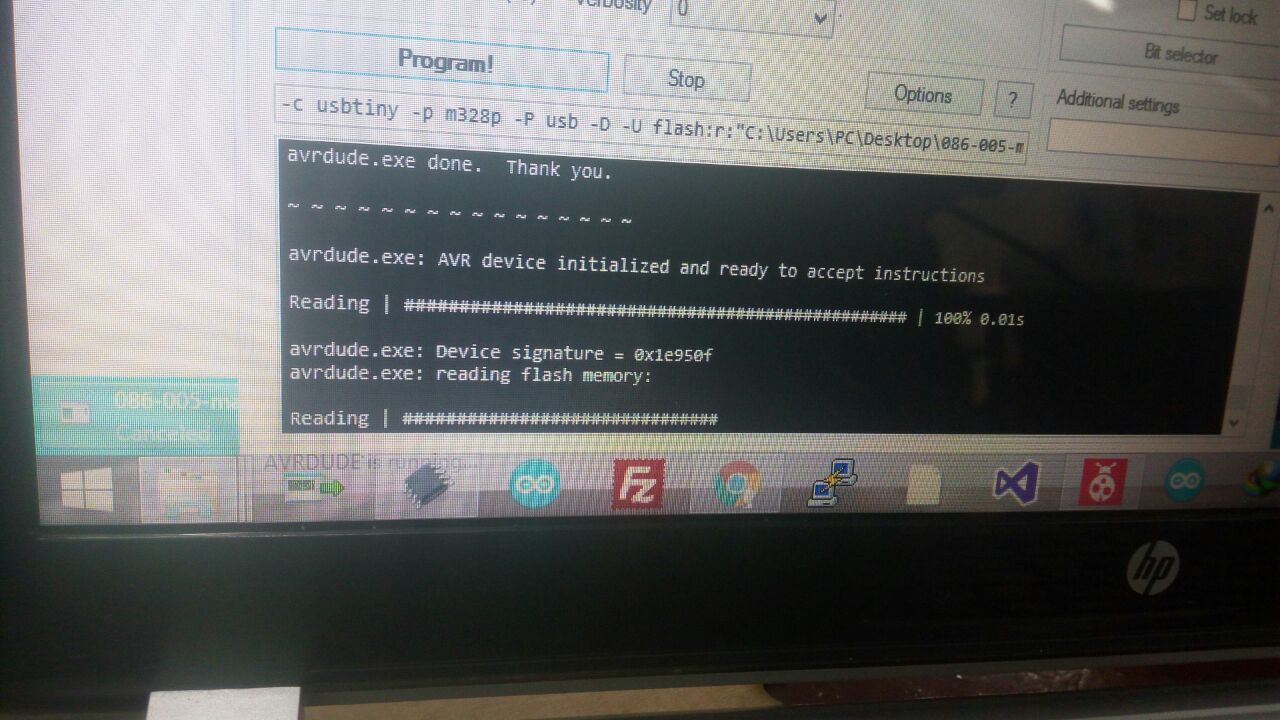
We received 3 Gestalt nodes together with motors and other things. When we did connections of these boards as instructed above, 2 out of the 3 totaly failed to be detected. Using the the troubleshooting instructions I received from the discussions in the mailing list, I tried but the same, one one was detected.On programming it we were able to blink an LED with it could not drive the motor at all. After alot of trials, even the LED could not light and therefore I quickly changed to commercial motor driver L298N
As shown below, we got to connect them well and programmed using arduino. They both were able to drive the two motors I wanted to drive shortly but they were overheating so much. One now could not rotate but just vibrate with alot of noise
- • To the Fabnet Board, Connect the Power Suppy 12V - 10A
- • Now, plug in the FTDI USB cable from the Fabnet to the computer running Ubuntu OS
- • Power-on but be keen since the Node do not have any protection. DO NOT HOT-PLUG
We are done now with connections and so moving to the next level
Electronics - Programming
Here we had to creat enviroment to program our boards to make them run the central motor which would make the rotating arm holding the Scanner camera move in the required direction. And the othe motor revolving a threaded rod which holds and makes the camera move in the Z-axix (up and down) move appropriately. Like Nadya with Gestalt (framework for virtual machine control of Automated tools), we chose to use Python
Having our computer with Ubuntu 15.04 handy, python and its dependencys are already met and so, we downloaded from Github pygestalt then relocate the folder to the Desktop for easy access.
Before running the python, We extracted all the files here

Friends who have been following my classes at a distance offered to be part of the Machine Building Group. And below is the list of members;
- • Caleb Eric
- • Felicity Mecha
- • Frank Ochola
- • Joshua Maiko
- • Bob Raphtone
- • Martin Oloo

Challenges
I got alot of challenges with some parts which which was compromising on the expected quality.
Below are overviews of some of the challenges;
- Motor drivers heating so much and do not run smoothly
- The revolving arm which holds the camera has alot of weight and getting a counter-weight is not easy to achieve
- Camera type, size and quality was not satisfactory
Changes and Improvements
I got another opportunity to make various changes on this machine especially after I settled on it as my final project. Below are areas considered and the way they were changed for the better;
- 1. Base/Casing - this cylindrical body part holding the electronic parts and provides the base for my Machine was changed from the cardboard to wooden parts. I used MDF which I machined in CNC Machine. The weight that this part has also provides for maximum stability needed to hold other parts ansd the camera.
- 2. The Machhine modelling changed from the revolving arm/ Camera to stationed camera but allowed the table to rotate
- 3. I designed, fabricated and produce a circuit board which would have the two motor drivers to run the two motors effectively
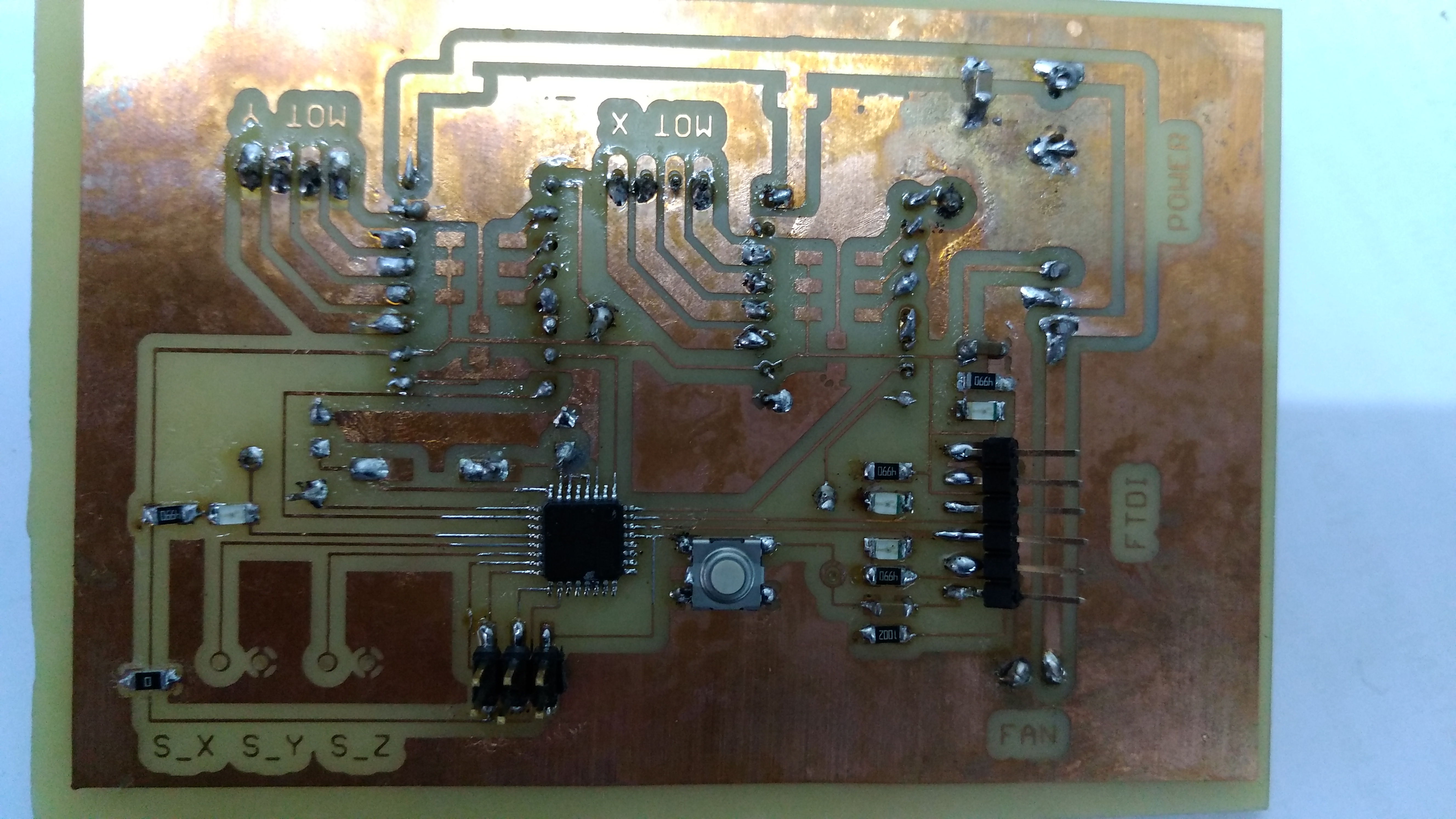
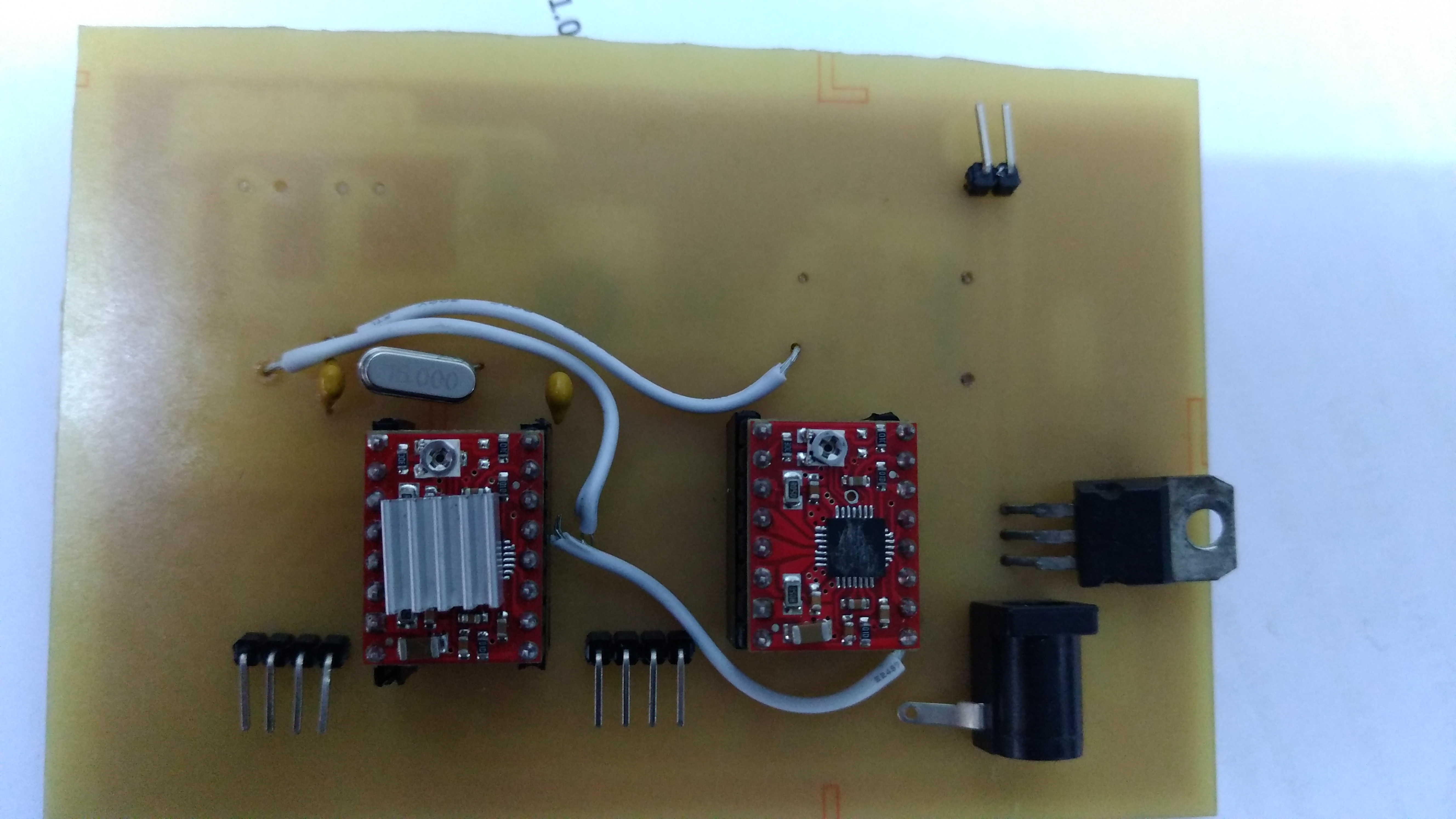
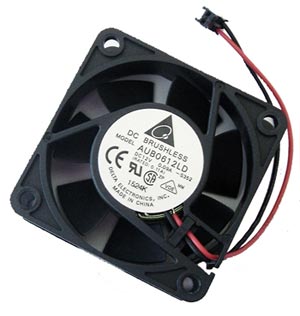
- 4. In Electronics, I introduces a fan which would help in cooling the heating motor drivers
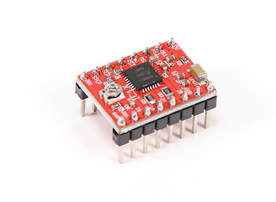
- 5. I also replaced the L298N Motor drivers I used initially to Pololu Motor Drivers
- 6. I changed from the previously used camera to a 3D RealSense Intel camera which has internal image processing capability. This saved me from other Softwares like COnstructMe or 123D Catch. This camera have multi advantage to my project since it is also small in size and light enough
- 7. I also 3D printed some of the parts like the camera holder from the initial laser-cut acrylic parts.
These improvements so far have changed the machine efficiency for the better. The machine packagine is now descent and meets minimum requirements for the fulfilment of the Assignment and Final Project
Files
- - Fabnet
- - Firmware
Other Important Links
● Machines that Make● Gestalt
● open3dge
● Python
● Working with Guids in Inkscape
● Guide to Vector Drawing in Inkscape