Like week 11 which was about Input Devices, this week's Lecture was on the Output Devices; how you use a microcontroller for processing output devices like LED lights, LCDs, Speakers, Piezo, motors among others and the implications of using them. One that stood out from the rest was the step response sensor which can be utilized to measure an array of properties like resistance, capacitance, inductance, position, pressure, proximity, tilt, acceleration and humidity. Also see this weeks' class Class Tutorial file to get an overview of the subjects in addition to the lecture you watched above. The Assignment was to measure something: add a sensor to a microcontroller board Fabkit board that you have designed and read it
Week 13

Output Devices
Assignment
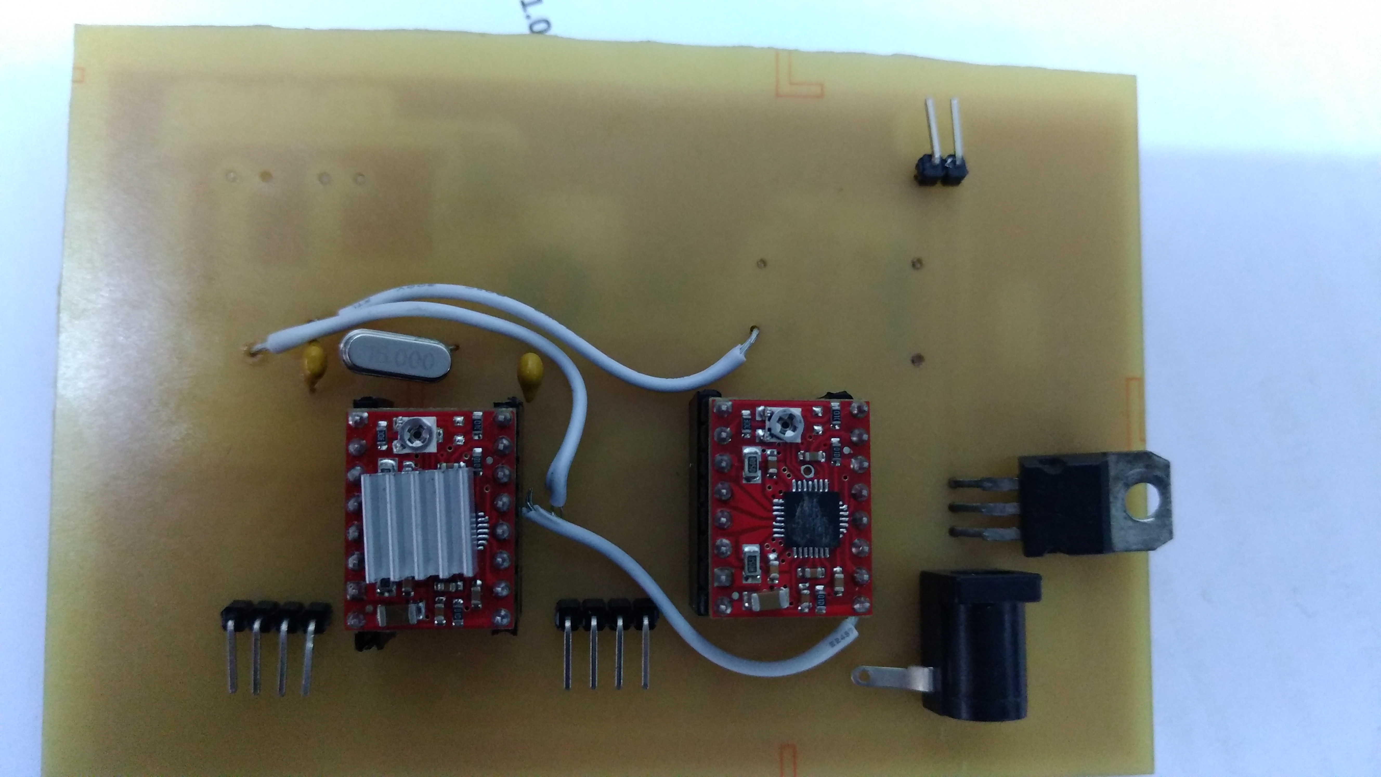
Final Project Board
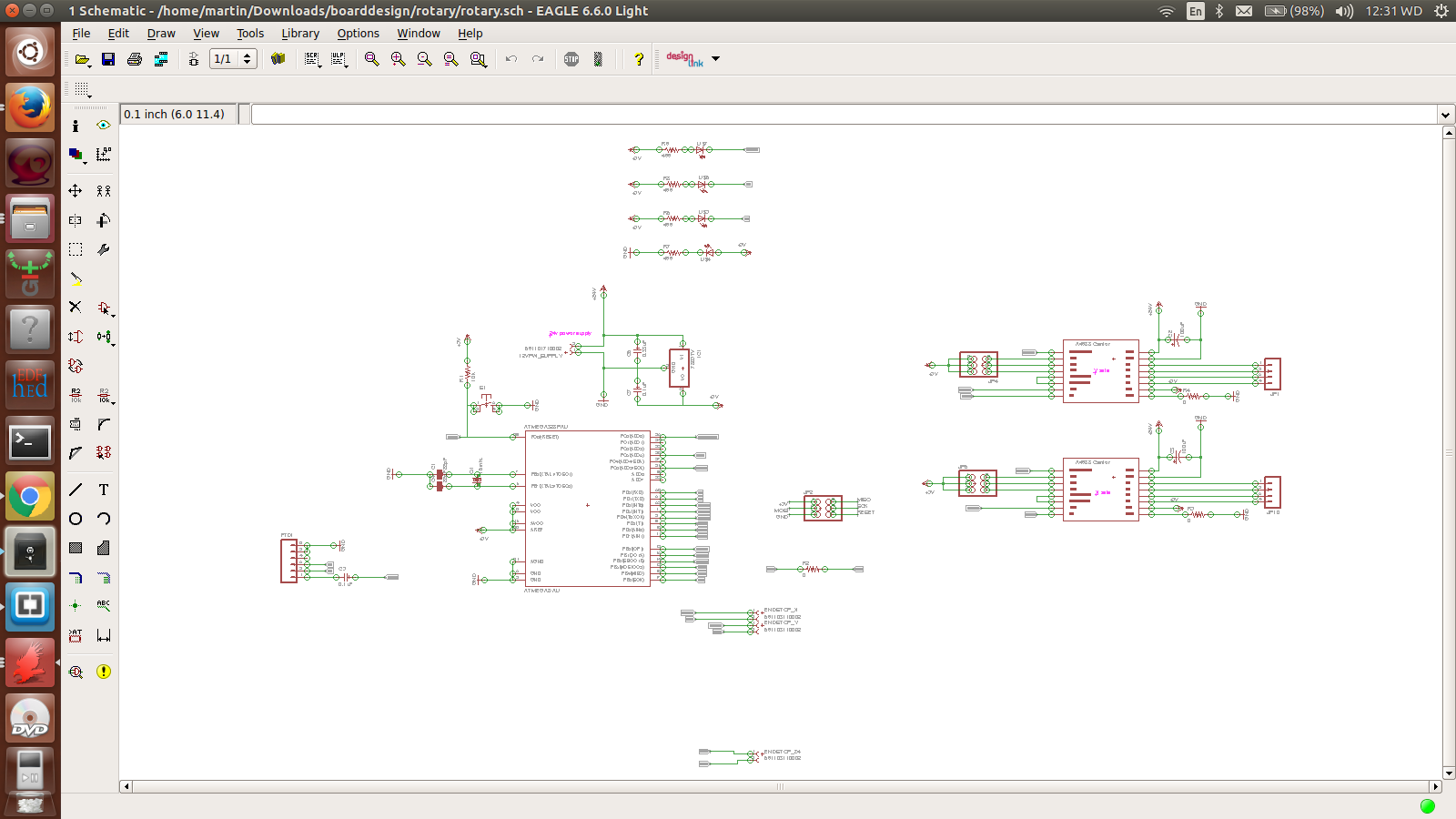
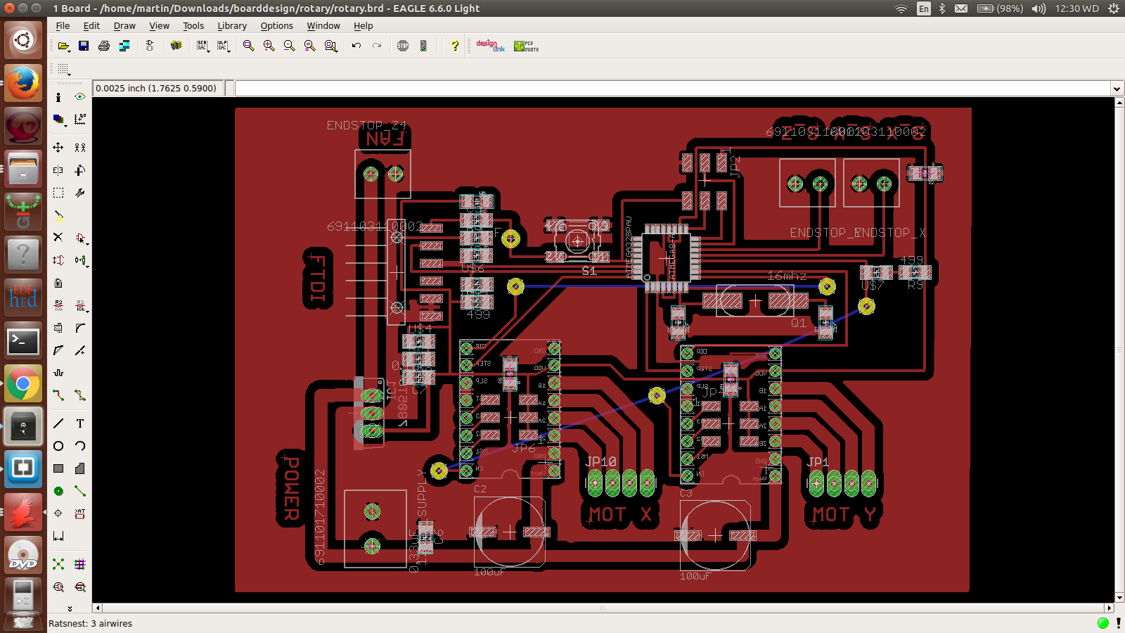
I decided to use this opportunity to develop a board that would then help me in my final project. For my case, i needed a board that would drive two motors. This in addition to the LEDs would gib=ve me a very good output devices.
I designed a simple board with atmega 328P chip with two Pololu motor drivers
Etching Process
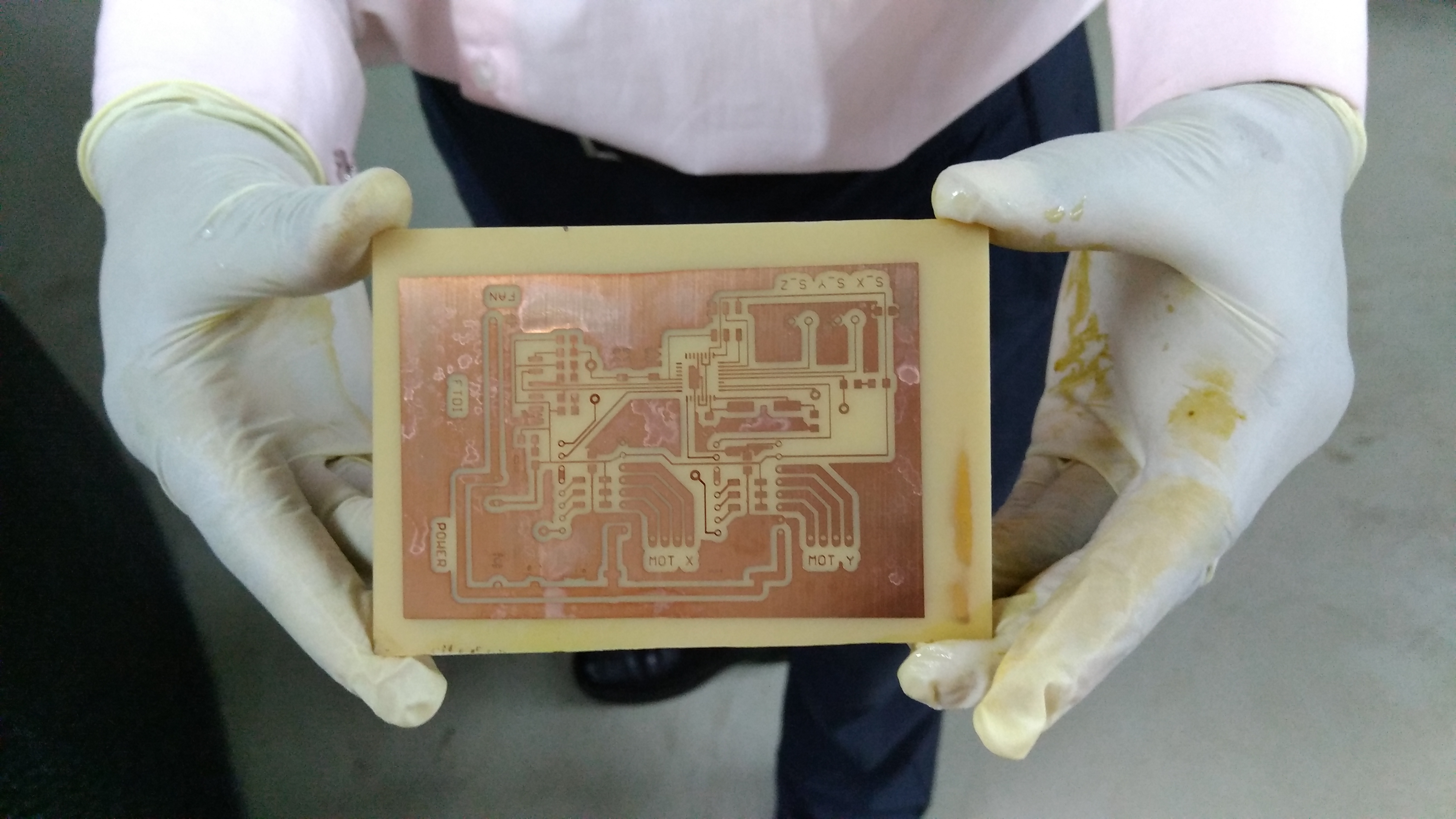
Just as explained earlier, I was using the chemical process to produce the boards. The Chemical at the Developer was highly concentrated that alot of boards got destroyed. This cahemical needs you to work with very high speed. The board from the exposure box is dipped into the chemical for 3 seconds. Any slight delay makes it eat copper beyond parts you wanted. Make sure you are well protected during this operation
Tinning
This is the process of dipping your etched board to the tinining chemical. This layer on the copper board which is also known as tin-plating makes it easy to solder as well as protecting the coper layer from decomposition by oxygen. I did my tinning but it looked awful so in my new board, I avoided it.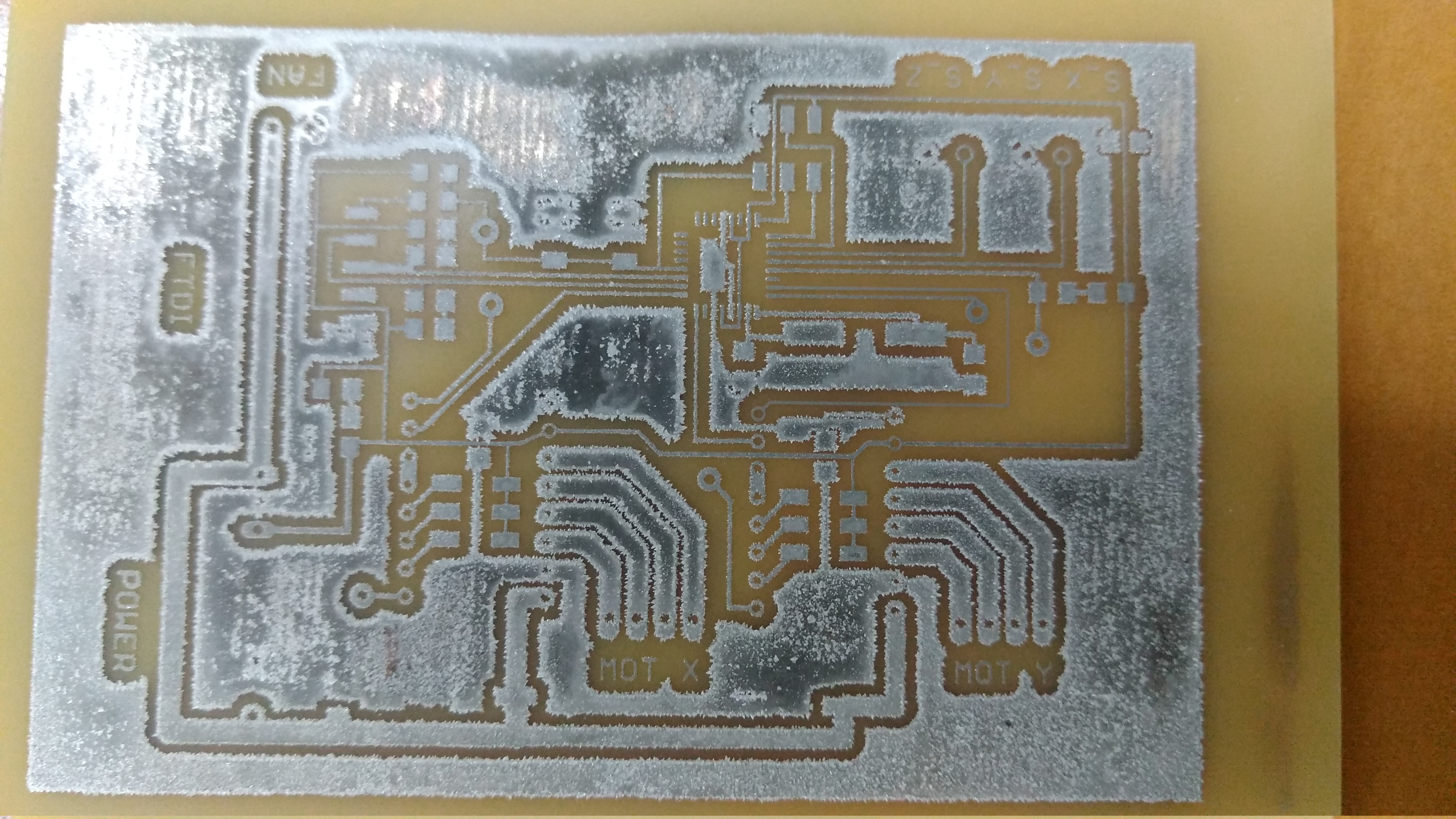
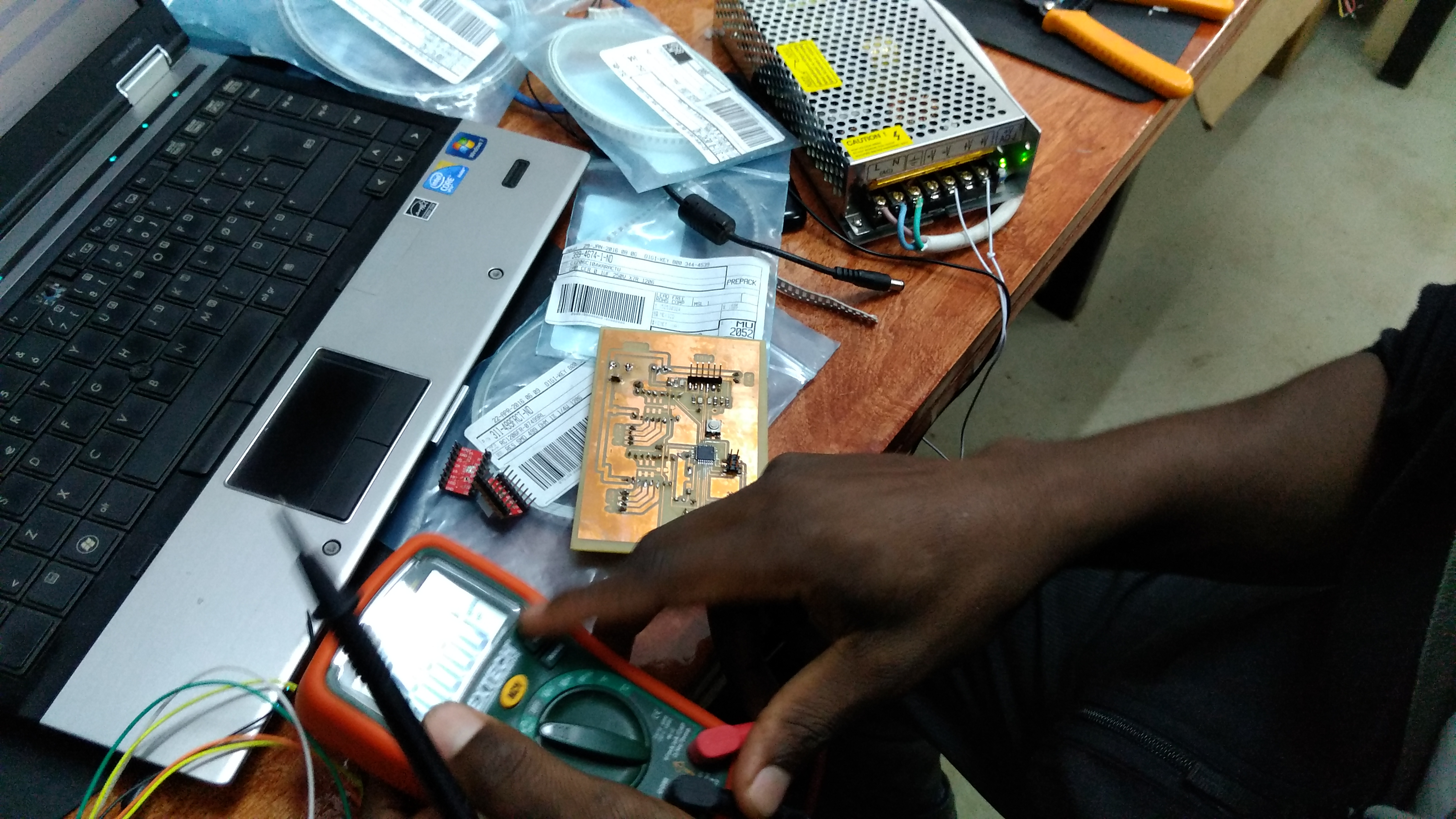
Run tests
When done with etching, use Multimetre to run continuity tests. This will help you know if there are any breakages on your lines. Suring soldering, you will run other tests like voltages among others
BOM
| PART | VALUE | DEVICE | CASE STYLE | PACKAGE | URL | QTY |
|---|---|---|---|---|---|---|
| IC1 | 8-bit | Atmega328P-AU | 32TQFP | Smd | 1 | |
| R1 | 10K | Resistor | 1206 | Smd | 1 | |
| R2, R3, R4, R5 | 499 | Resistors | 1206 | Smd | 4 | |
| R6, R7, R8, | 0 | Resistors | 1206 | Smd | 3 | |
| C2, C3 | 22pF | Capacitor | 1206 | Smd | 2 | |
| C4 | 0.1uF | Capacitor | 1206 | Smd | 1 | |
| C5 | 0.33uF | Capacitor | 1206 | Smd | 1 | |
| C6, C7 | 100uF | Capacitor | 1206 | Smd | 2 | |
| LED | Red | LED | 1206 | Smd | 4 | |
| XTAL | 20Mhz | Crystal | 1206 | Smd | 1 | |
| Voltage regulator | 7805 | Voltage regulator | 1206 | throughhole | 1 | |
| Omron Button | Press button | 1206 | smd | 1 | ||
| isp | Header Pin | 1206 | smd | 1 | ||
| FTDI | 6 header pin | 1206 | smd | 1 |
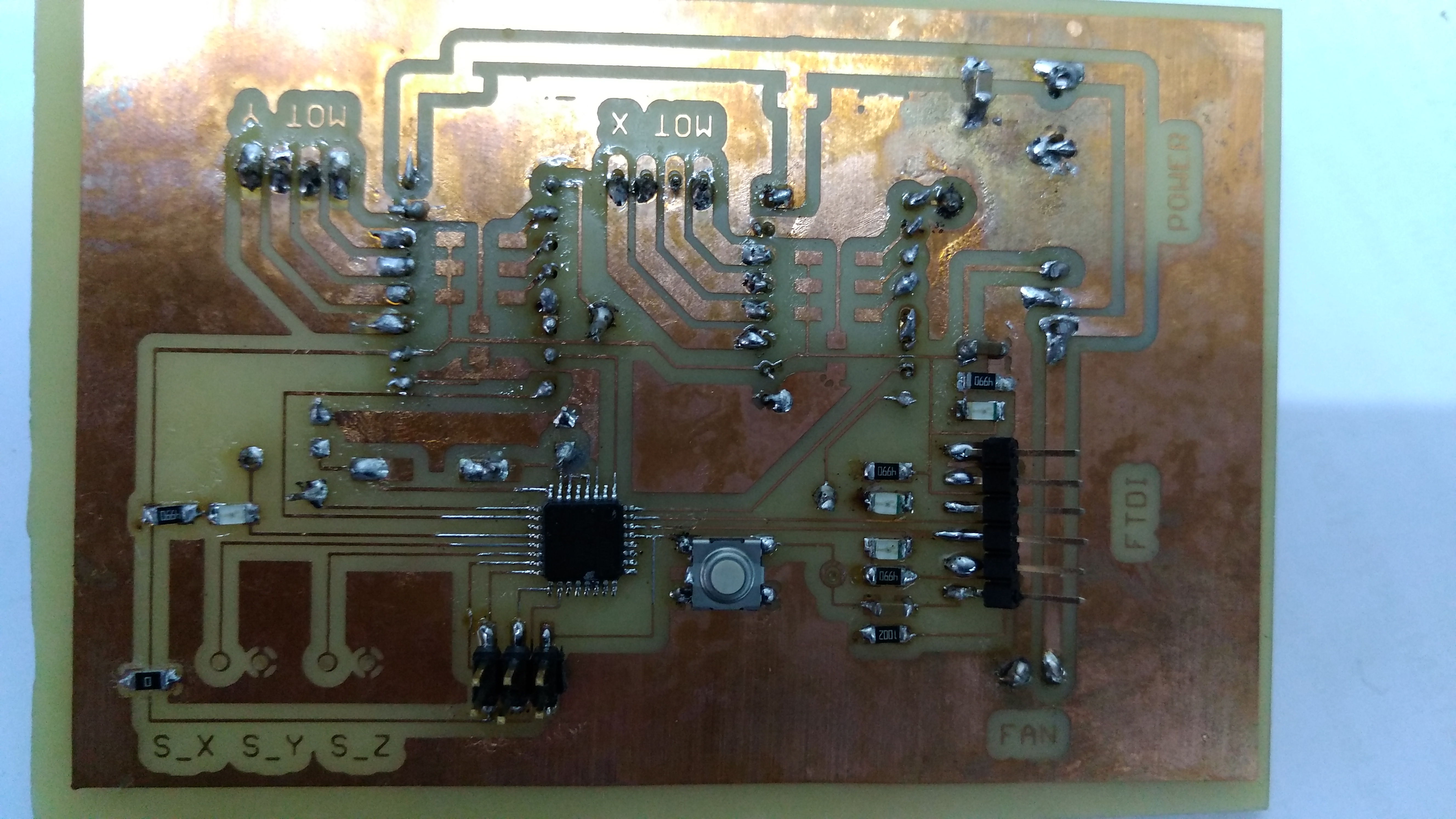
Soldering
I did a very nice soldering for the board shown below better than all the past by making sure that motor drivers can only be plugged in and out but not soldered. I also made sure that all the parts which needed through hole components are placed appropriately
Softwares
The Softwares used here included;
- • Arduino (1.5.4
- • Atmel Studio or
- • AVR Dudess
Detecting ATmega32
Here, the idea was to develop a circuit that would produce an effect through an output device. I chose to use my board which was designed for my final project. It was driving two motors which were to aid in the movement of the 3D scanner. It also had LEDs as additional outputs.
When programmed, it drove two motors simultaneously as shown below
Connect ATmega 328 microcontroller to the USB programmer as shown below;

Board2
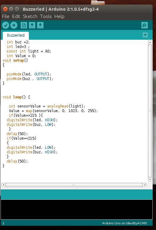
This same board I used for input devices was also helpful since I placed buzzer and LEDs on it
Like the same program in the input devices, the buz buzzes when the LDR is uncovered but stops when the light intensity of value 251 and stops when covered
 Buzzle Output
             int buz =2;
              int led=3 ;
              const int light = A0;
              int Value = 0;
            void setup()
            {

              pinMode(led, OUTPUT);
              pinMode(buz , OUTPUT);
            }


            void loop() {

               int sensorValue = analogRead(light);
               Value = map(sensorValue, 0, 1023, 0, 255);
               if(Value=>215 ){
              digitalWrite(led, HIGH);
              digitalWrite(buz, LOW);
               }
              delay(50);
              if(Value=<215)
              {
              digitalWrite(led, LOW);
              digitalWrite(buz, HIGH);
              }
              delay(50);
            }