The assignment for this week had the following four parts;
- • Redrawing the "echo hello-world" board
- • Adding (at least) a button and LED (with current-limiting resistor)
- • Making
- • Simulation
Re-drawing the "echo hello-world" board
Using EAGLE software, "echo hello-world", provided for the assignment, I managed to obtained the diagram of the original circuit.
Follow the process below for Schematic Wiring;
As you start watch thisTutorial first
- • Obtain the original circuit board: Eagle
- • Download and install EAGLE software
eagle_libraries.zip
- • Download the components libraries from the following link: eagle_libraries.zip
- • Unzip and save in the EAGLE libraries folder.
- • Go to options menu, then directory where you will paste the link of the folder of the library files. Use semi-collon to separate them in windows
- • Then to create a new schematic diagram, go to File/New/Schematic
- • Go to Library then right click your library you copied and click Use all, to load the libraries
- • Edit/Add, to include the library components to the diagram
- • For wiring, you can use wires or Net, to make the connections; if Net, you can either make complete connections or naming parts accordingly
- • Name, Value, to register the adequate names and values of each component
- • Label, to include in the diagram relevant information for understanding and to link components
- • Move, Mirror, to locate the components in the template
- • Use Delete, to delete the connections or components
- • Tools/ERC , to verify program errors and warnings
- Export/Libraries, to export in a .lbr file all the components used in the diagram.
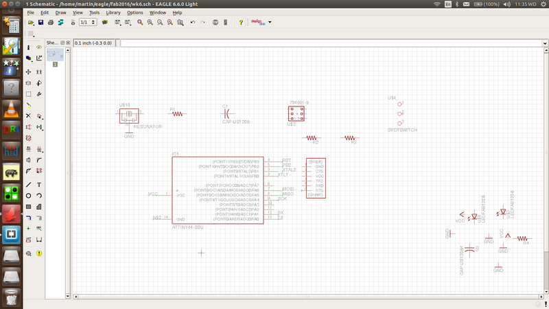
Schematic provides you with environment of designing the board using the electronic symbols
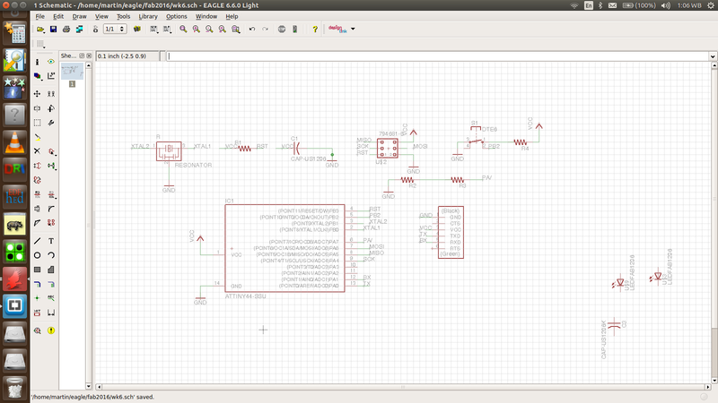
In connections, you can either use wiring of net. Net also provide you wiyh option of direct connections or simply using small connections and naming them hence they get connected at the background. This leaves your board look more neat and easy to manage. That is what I used.
From the Eagle folder, I pasted the .lib I downloaded into the library folder and called it "mylib".
I also went through a rich tutorial
Tutorial from which I was now able to pick all the components and place them. Mastering a few tools on the window, I managed to do that and using the "net" command, I wired them and here, I was ready to move to the board to see the result. As expected, they were so much jumbled up and since, I was following tutorials bit by bit, I went back to see how to arrange the layout
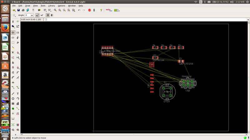
Switching to board from schematic. This will now let you route your connections well and makes it ready for milling and drilling depend on your board and components expected to use
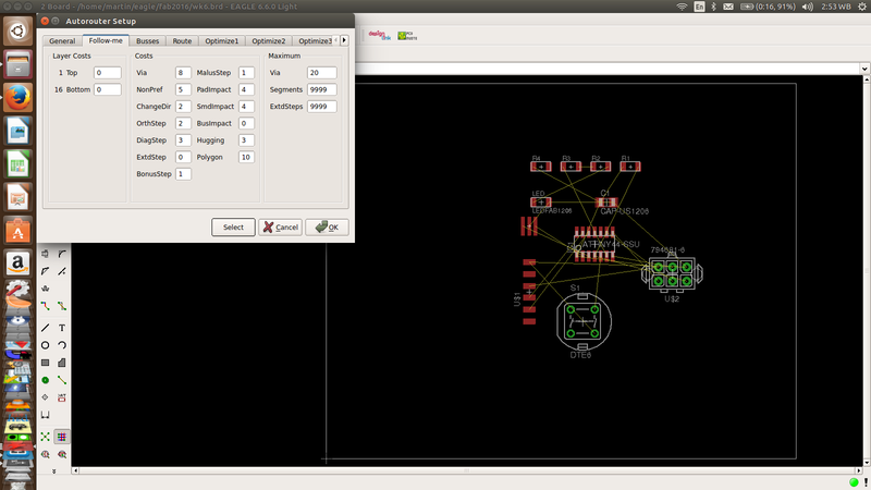
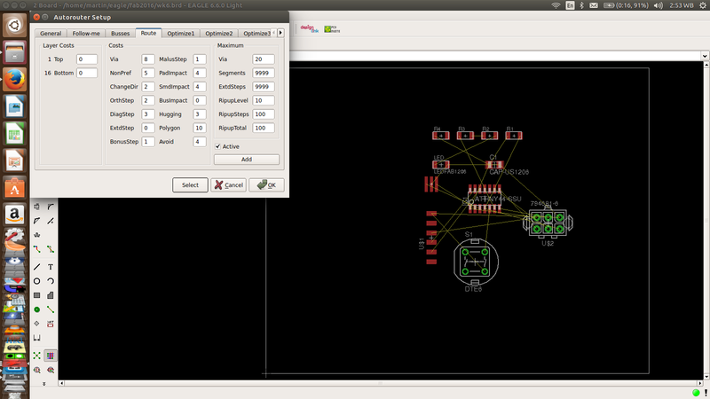
First, all of the components appeared outside the board area and I didnt know how to move the board boundaries to cover my work. Now, I was pulling individual components to the right place. After this, I decided to escape the burden of manual connections and for this, I went straight to Auto routing and there,I was done.What next? Resizing the board and working on the layers.
Obviously there was an error here. The green circles seen shows that I chose through-hole components which were not a requirement for this board.This was caused by limitation of the library provided and so I got other two more libraries which could now give all that were needed
I did not realize that Imediately and continued to struggle arranging my board for routing
I was in a hurry to see my board ready so that I can mill it
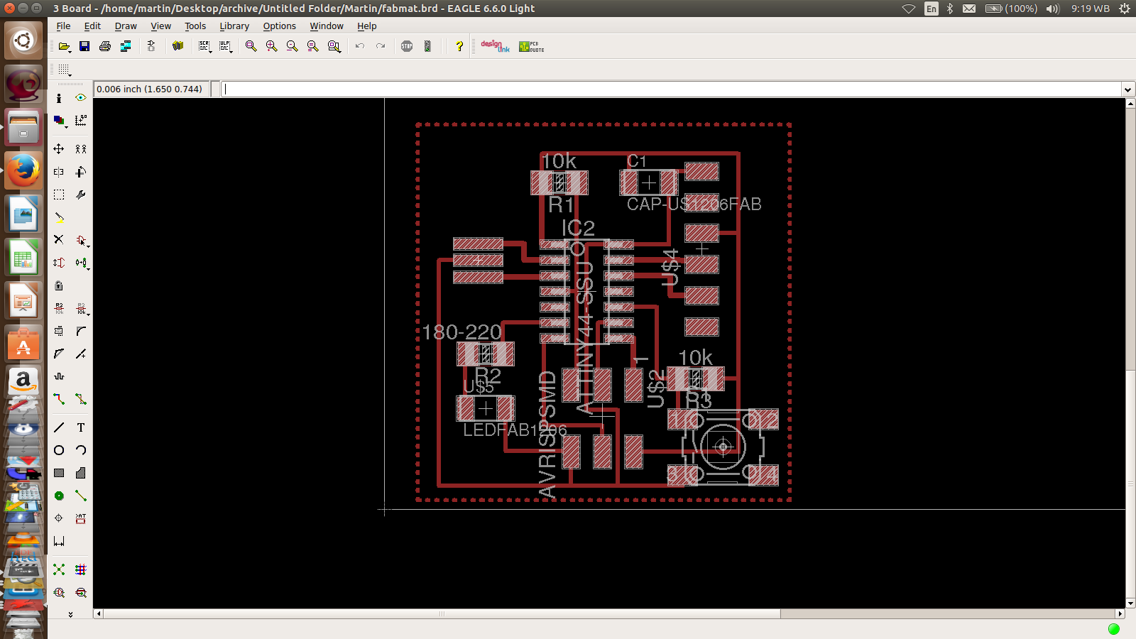
Aha, after luis seing my work, he pointed out the error and together we established the cause. I got the right liabruaries and replaced the through-hole components with SMDs
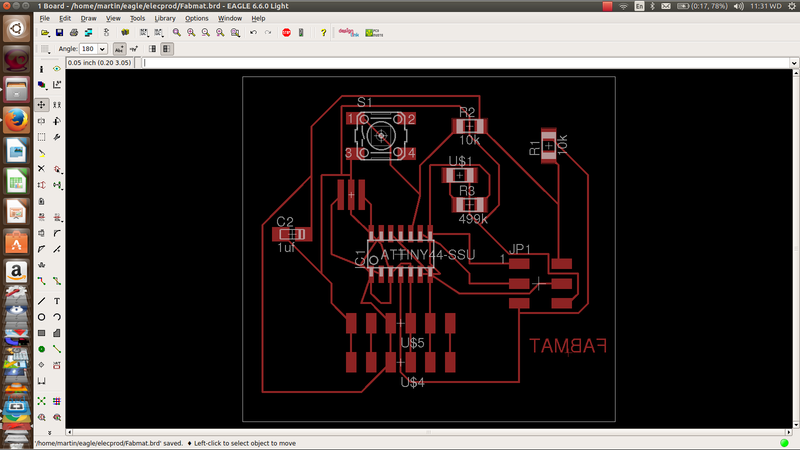
Looking better now? I continued struggling with arrangement but even after the Instructor told me that the board was so simple to arrange, I was still using autorouting which was leaving some airwires. I became nervious and got a trick of deleting the two wires which could nout be routed with a plan of connecting them during stuffing of components. Wharning: Dont use it. This my idea was thwarted out and Luiz took me through step by step routing. True to his words, it was now so easy. I spent the night practising the same
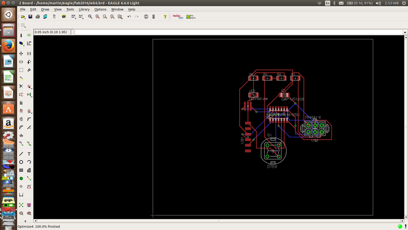
Finally, I got the board I really wanted with full correct routing
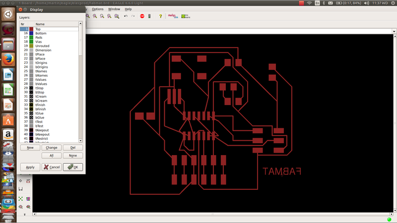
Make sure you switch off all the layers you dont need from the view/layers menu. Also check any errors before moving to milling
Downloads
Fab trialFabmat
Fab tr
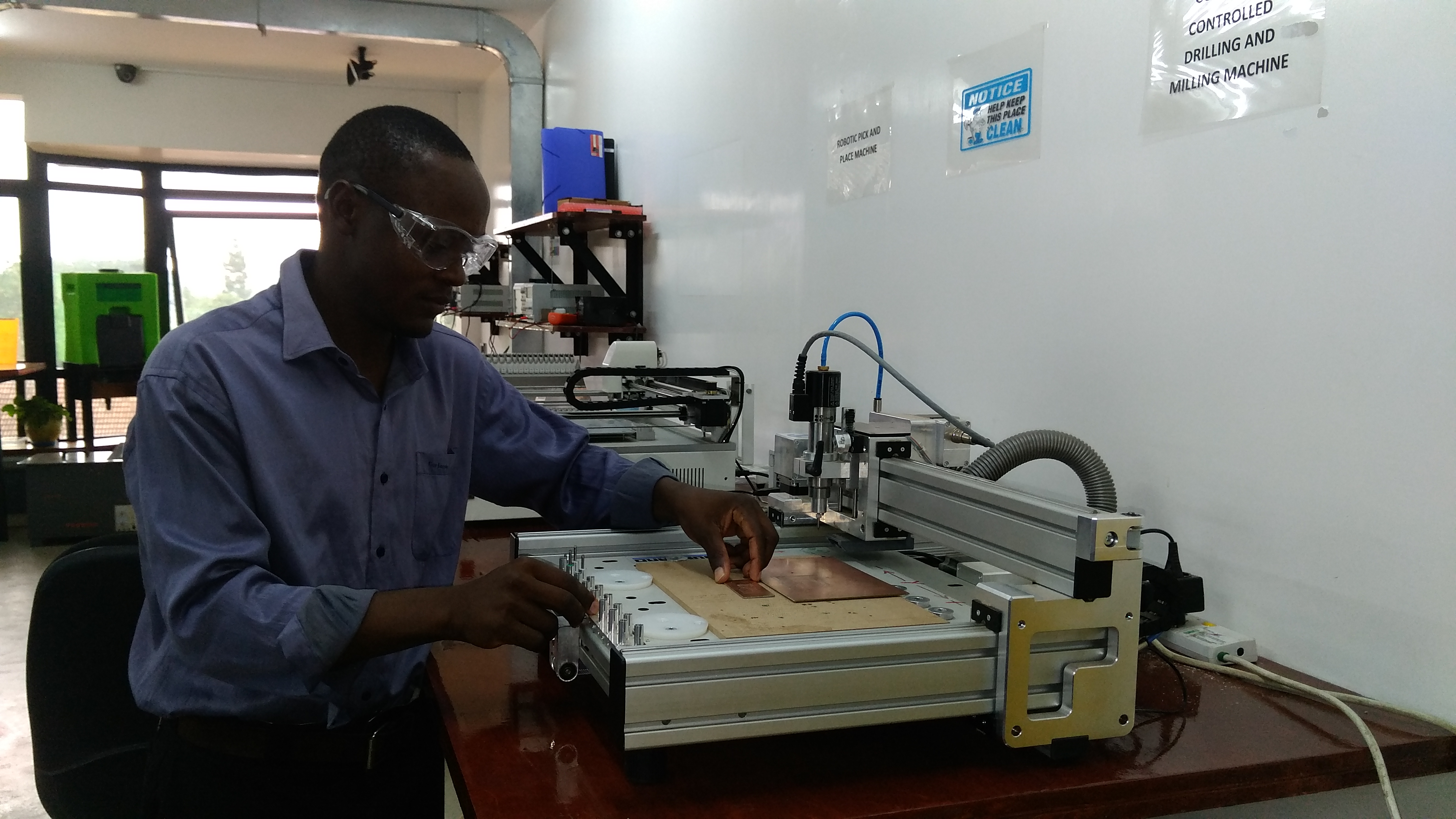
Milling
Export the circuit as a monochrome.png
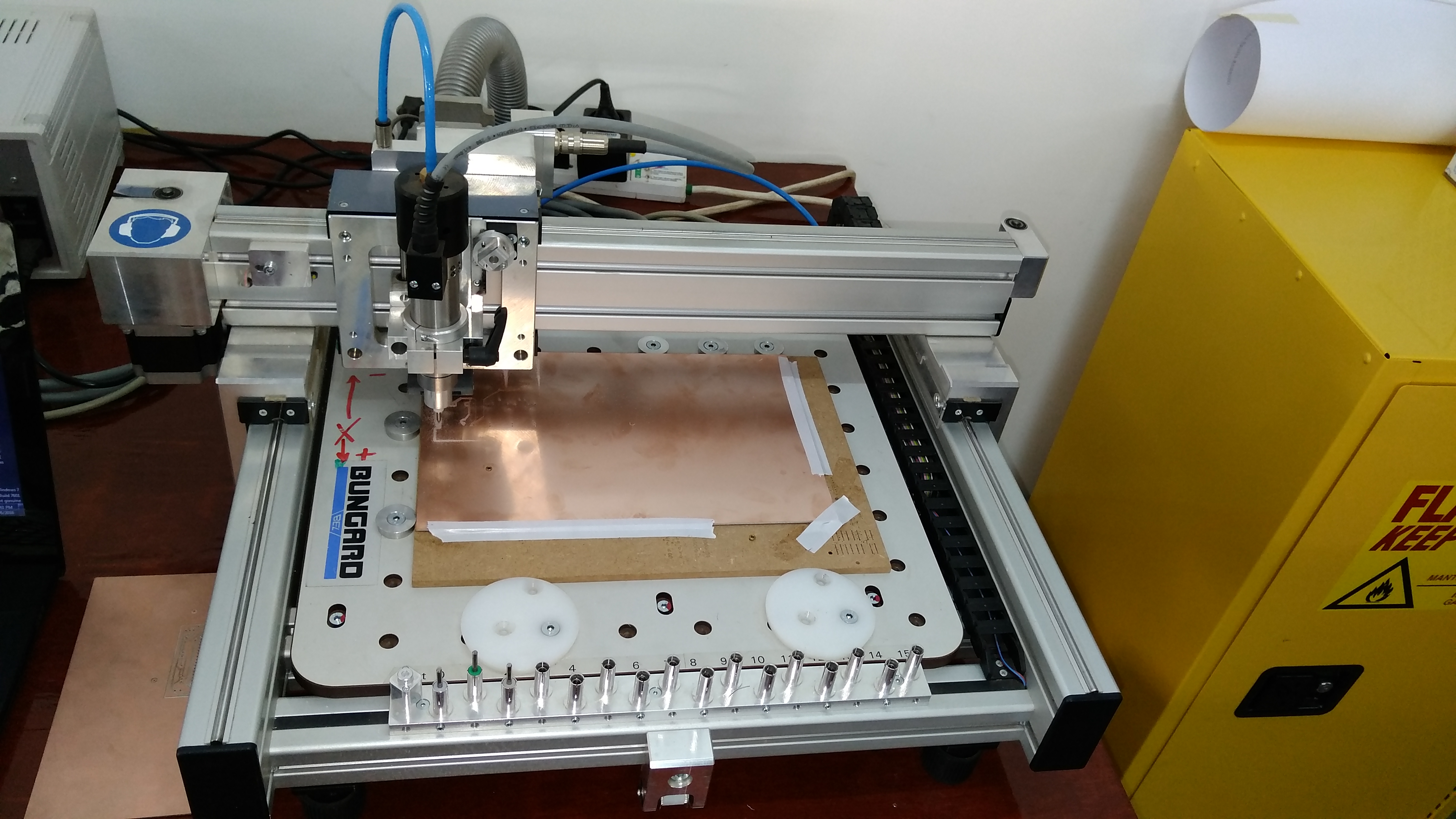
- Lay the board on the work table and do necessary adjustments
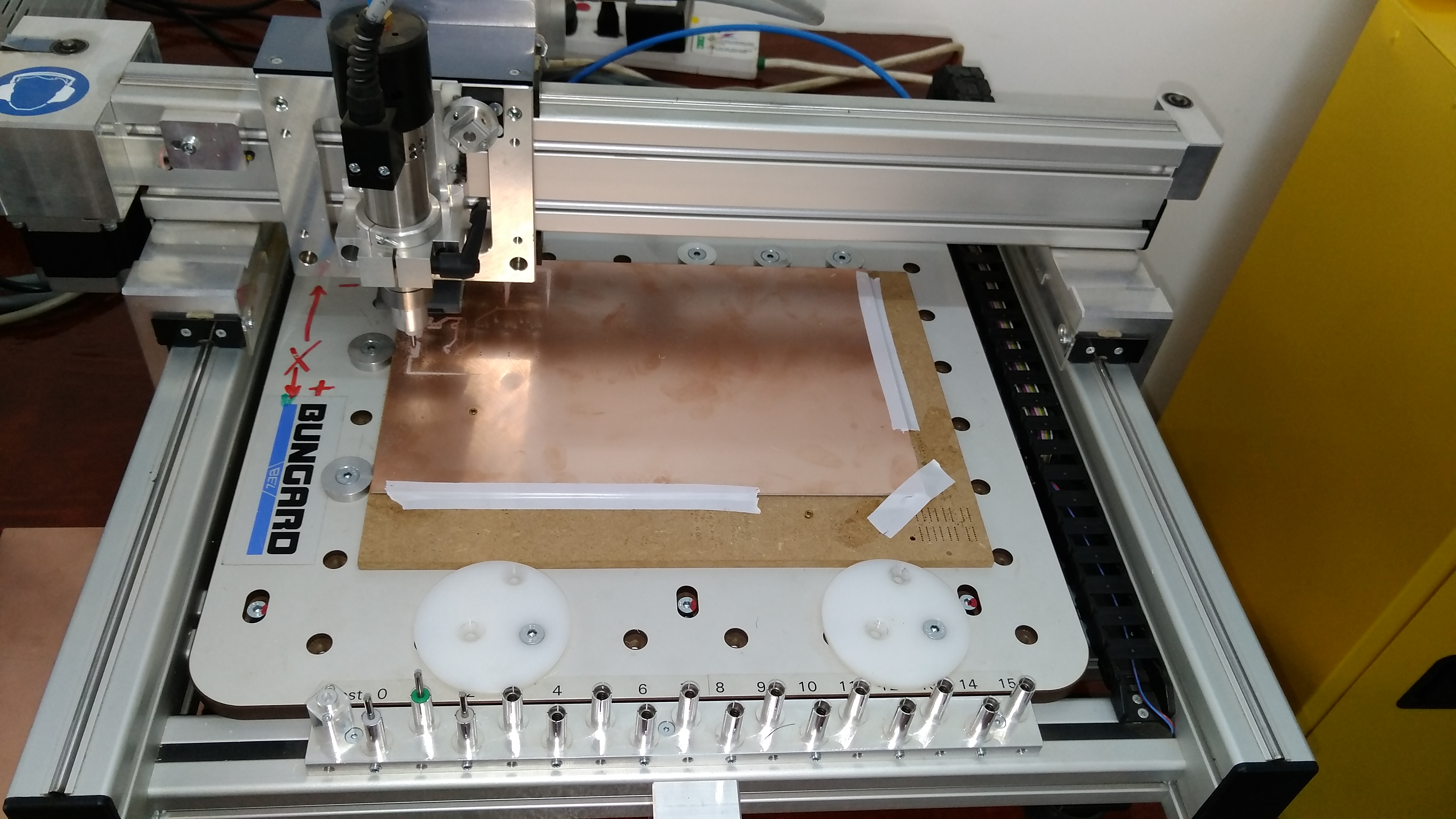
- Set the Zero for the X and Y positions
- Mount the right tool for the first session of the cutting/ drilling whatever the case i.e 1/64" or 1/32"
- Do the above by moving the tip close to the surface until it touches it and set your Zero
- On completion of the first part, adjust the Z-zero only. Dont interfere with X or Y
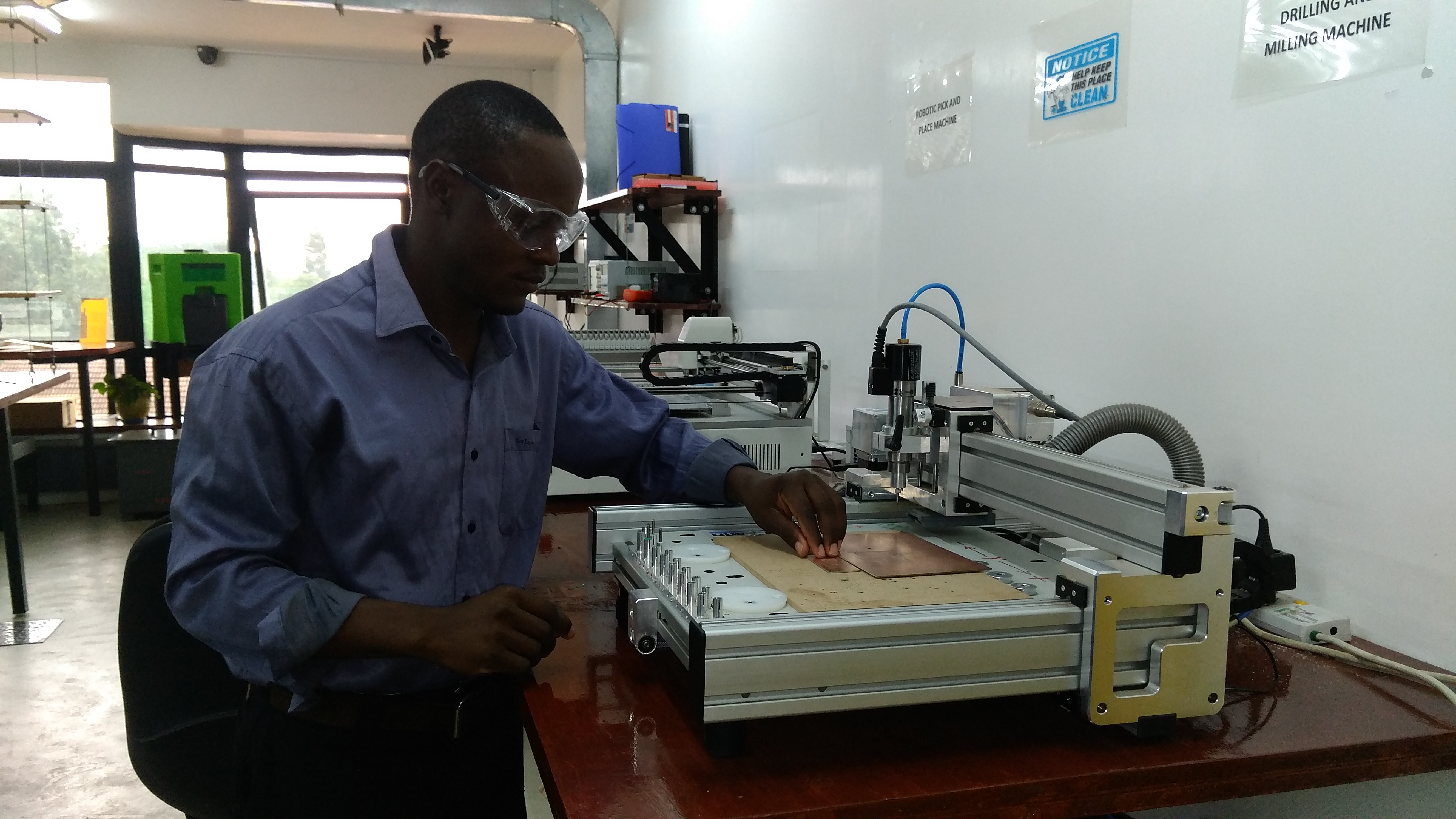
- Make sure you wear protective gears especially for eyes and ears
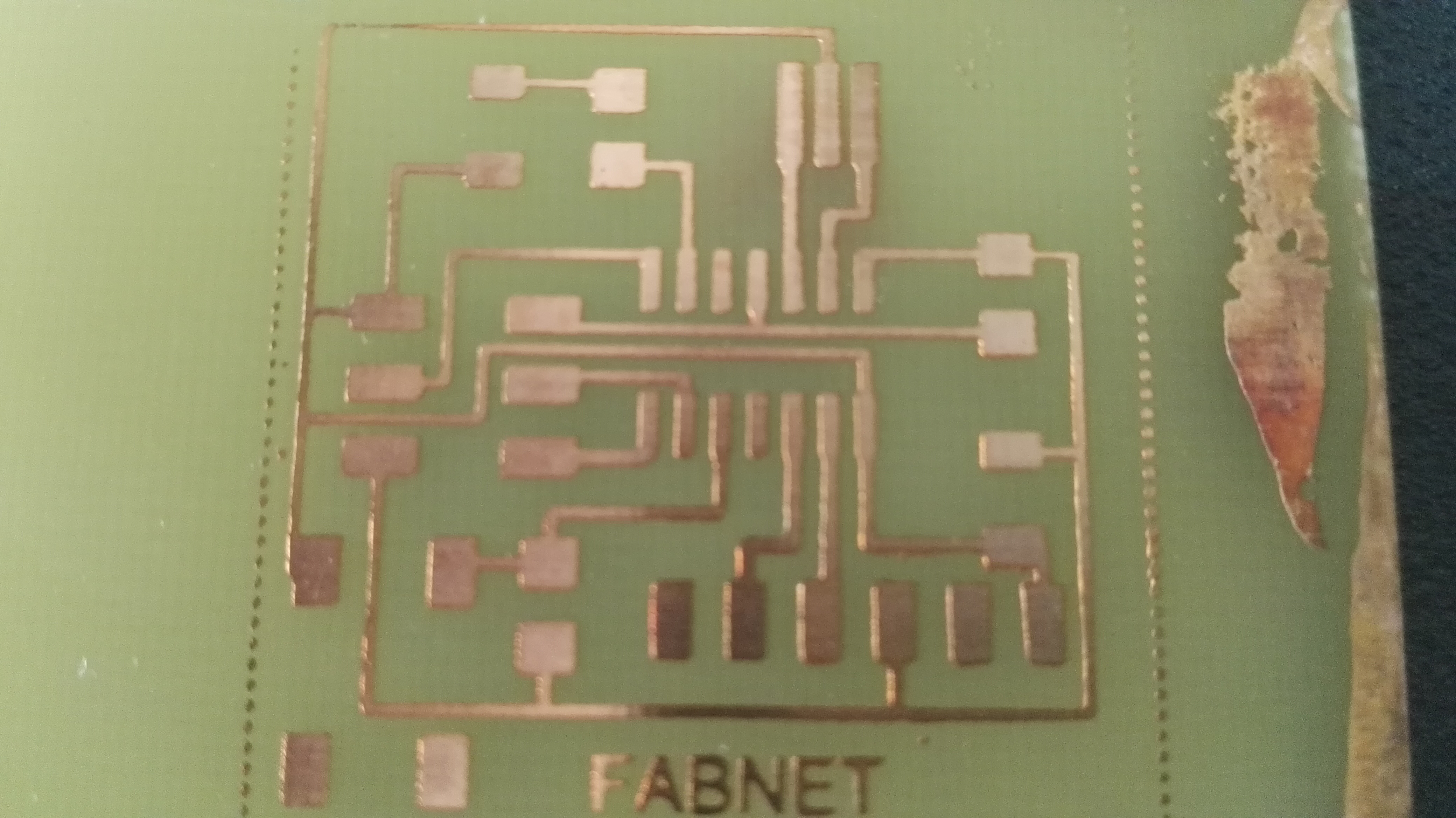
When finished, remove the workpiece from the machine
- Wipe away the dust ao wash the board clean taking care of the fine particles not to prick your fingurers
- Check for any errors. Incase of any unwanted connections, use a gullotin cutter to separate them in according to the design
- Clean the board with water and soap and be keen not to touch the surface now
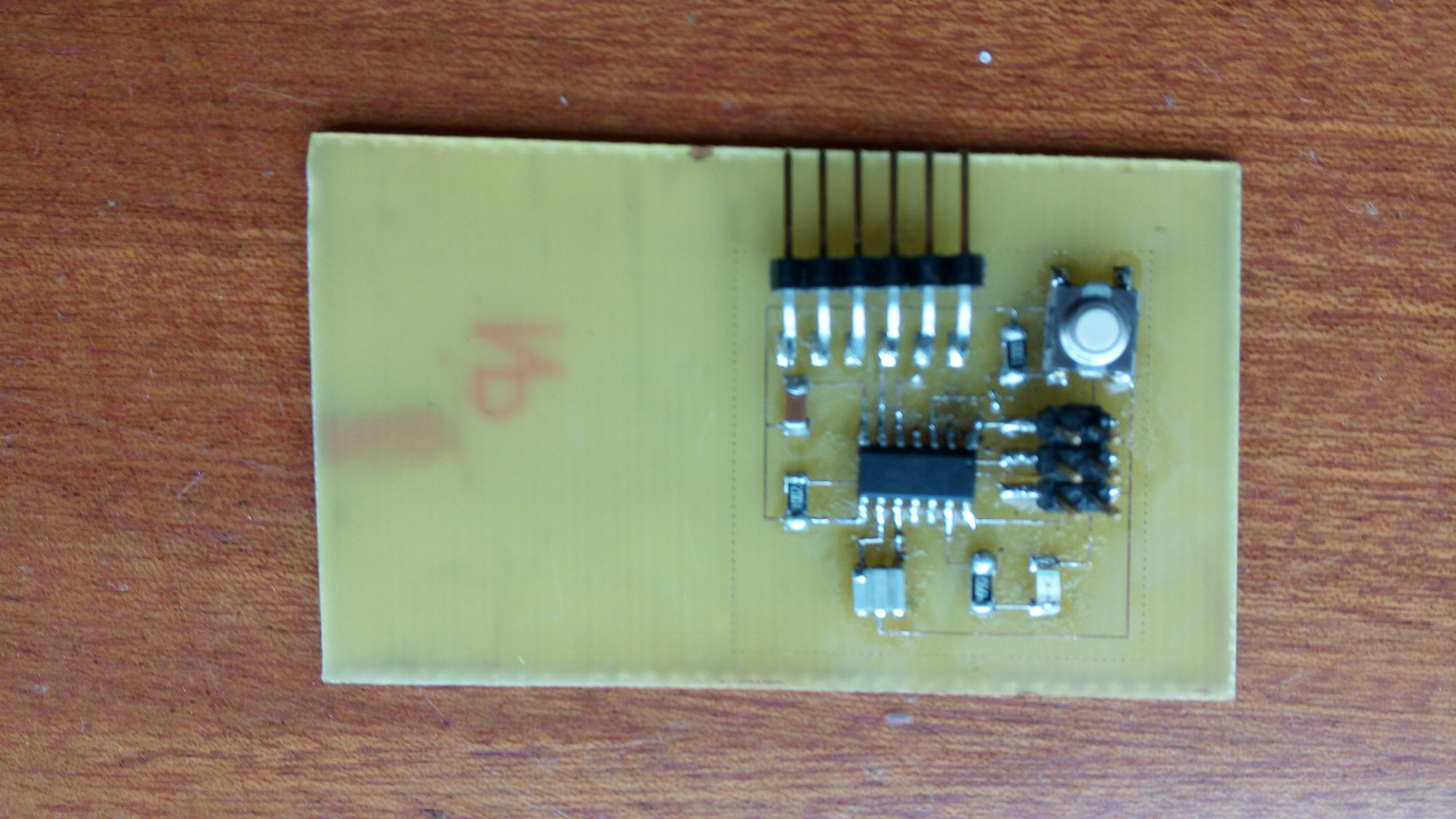
Anyway for some reasons again, I used the Etching method and equally, the board looked so neat with clear tracks
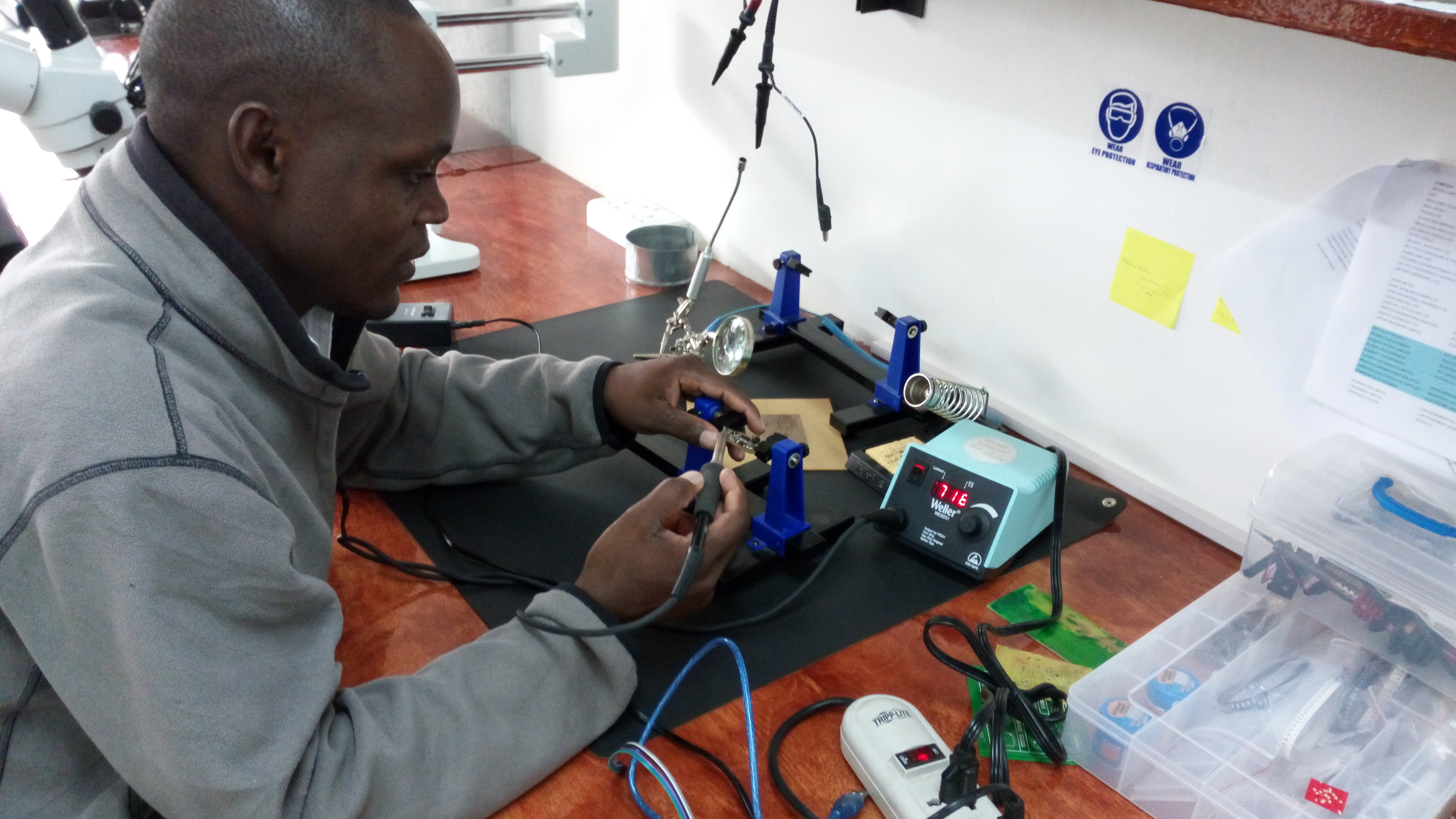
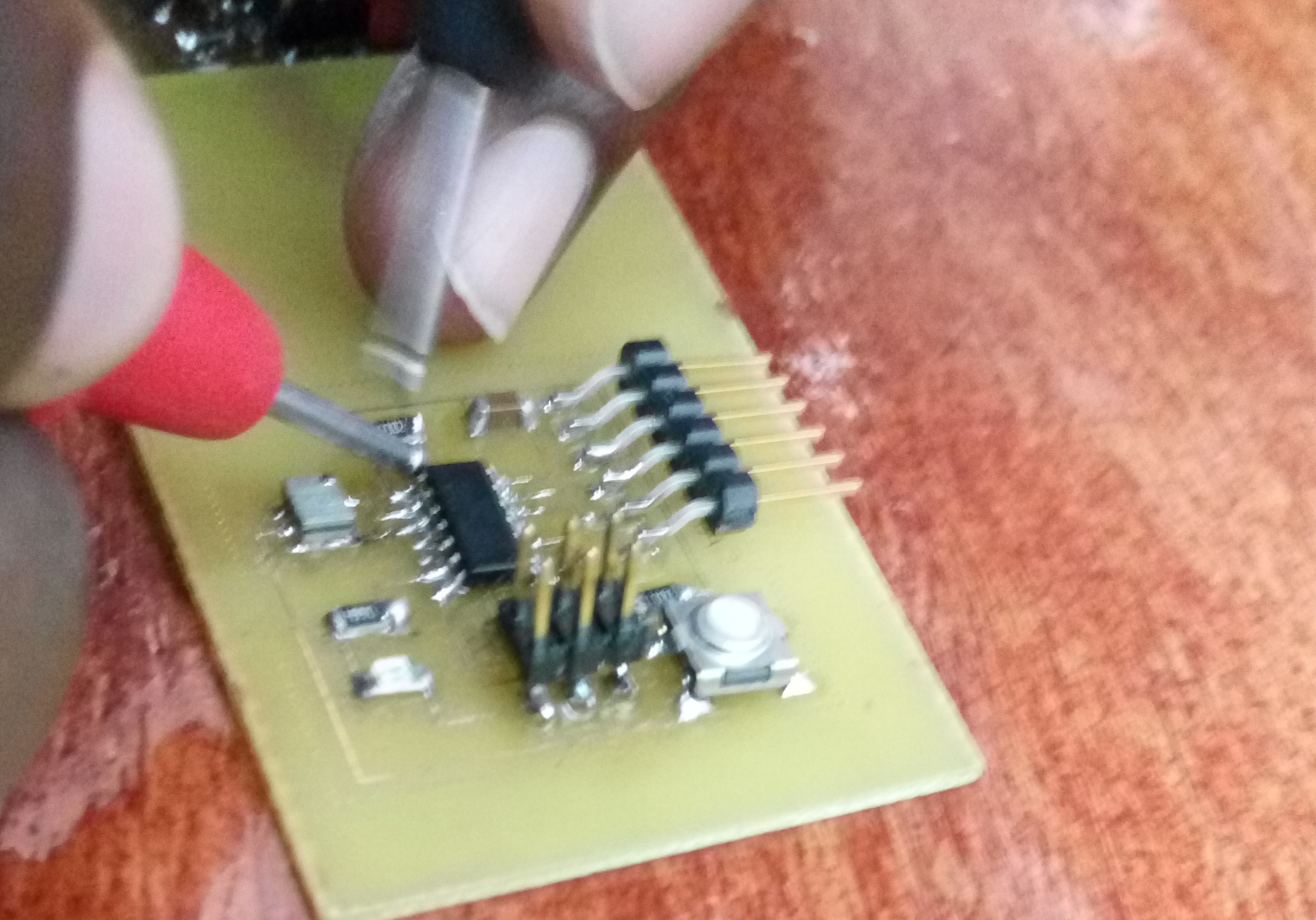
Soldering
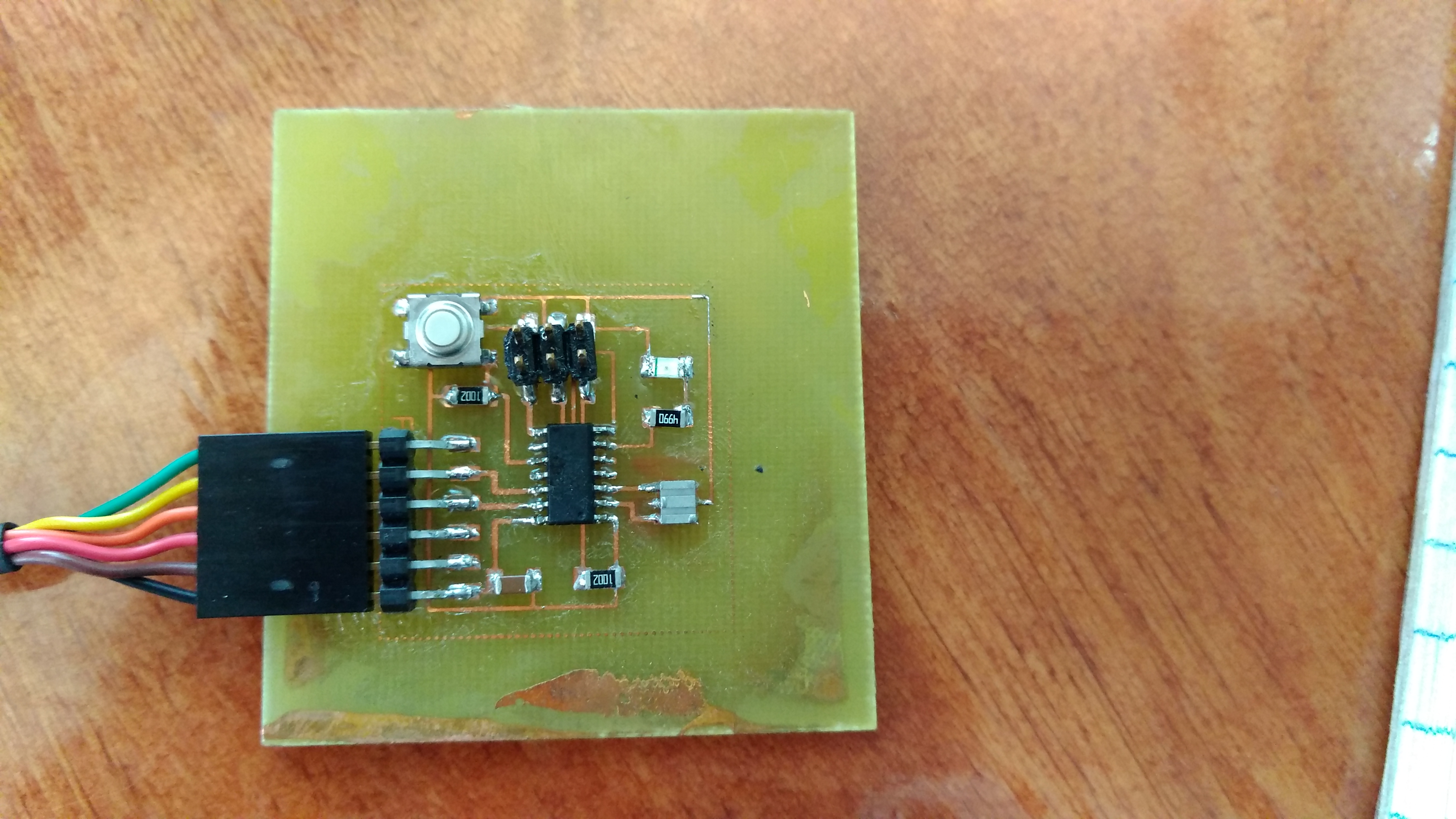
Solder all the components in accordance to the plan. Be keen to the orientation of your MCU
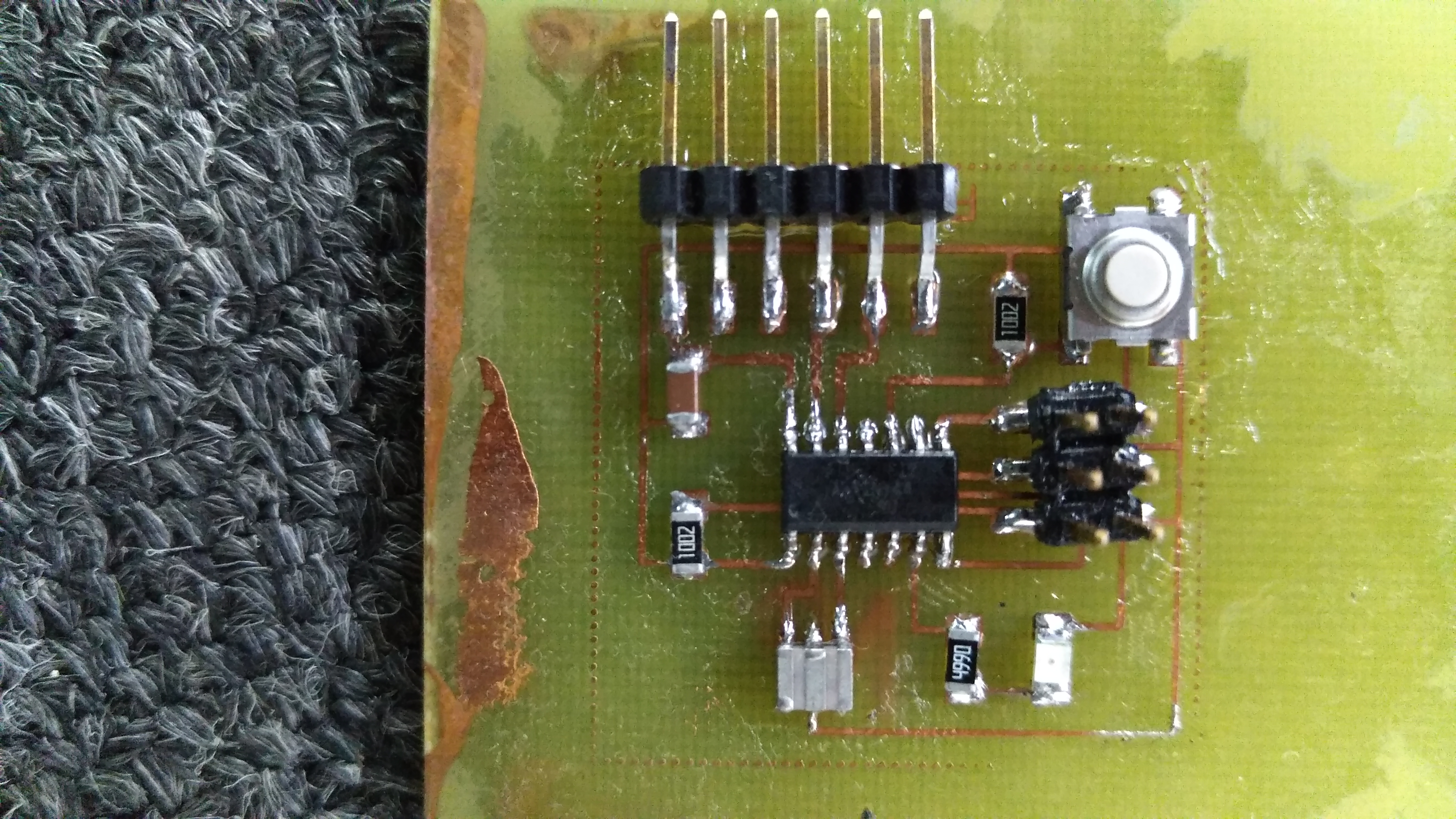
Again just like in week4 Assignment,I soldered the below listed down comonents starting with the MIcrocontroller
- • ATtiny 44A Microcontroller
- • 3.3v Zener Diode
- • LED
- • Omron Press button
- • Resistor
- • Resonator
- • Capacitor
- • Six Pin Connectors
This board did not have so many components and so soldering process was not complicated. After soldering the Microcontroller, I then soldered others including resonator, diodes pins, capacitor, LED and Press button. It was completed well.
Using multimetre, I subjected the board to continuity test after clearing soldering. Here, everything went well so fast
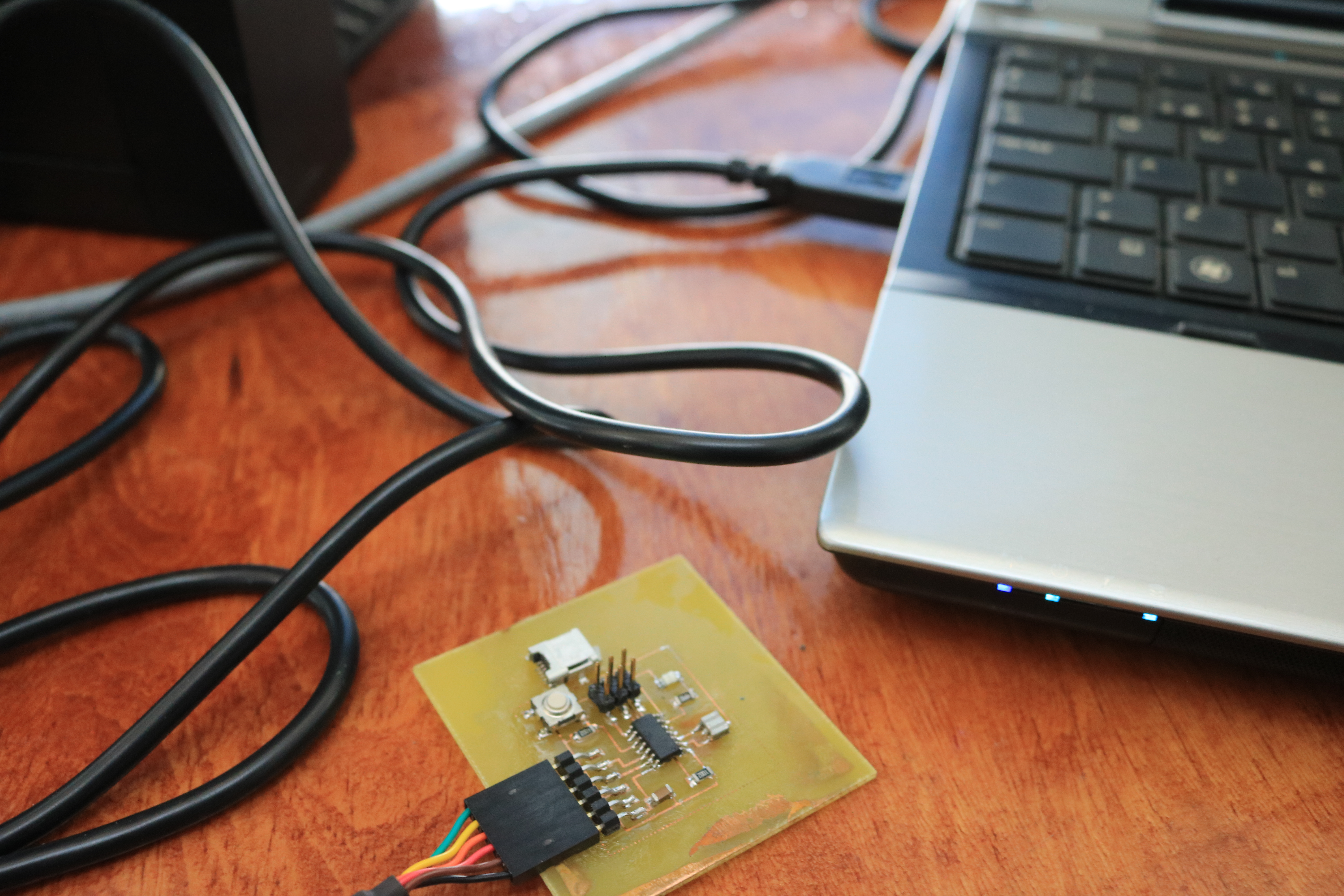
After the test, I decided to connect it t the computer to see if at all it can be detected by the computer.