Project Development
For developping that project, I learn to do the progress very little step by very little step. Because I wanted to do a project very complex, I knew that I couldn't do everything I wanted all by myself. So I started very easy then I define the next little step and improve the project every times I had something that worked, and improving it again and again until the deadline. Here are the step that I followed : 1-Read the input of a resistor Very first step. I tried to plug the resistors from the VCC to the analog input put it didn't work. So I checked about how does a potentiometer work to get inspired. I learn about the voltage divider principle that I will use anytimes in that project. Sparkfun have very good tutorials about basics knowledge in electronics. 2-Convert the input into resistors value. Because Arduino input convert the voltage into a value between 0 and 1023, I had to do an equation that convert that value into a resistors value knowing the input voltage (5V) and the first resistors from the voltage divider. It was probably not really necessary but usefull to check if the system was working fine during the development. 3-Communicate from arduino to grasshopper I heard about the firefly pluggin that allows grasshopper (a parametric pluggin of rhino) to use the serial communication, making easy to generate 3D with arduino input. I had to change the firmata of my board and do a couple of setup to make it work, then I did the very first succesfull test of tangible interface, the easiest possible.
Tangible cube using resistors from hugo moissinac on Vimeo.
4-Define a real concept Then it was time to really define how will it work, what will do what, which parts will I need, what should I learn, etc ... I first thought of doing a 3D multiplexing of resistors, some kind of reverse (input instead of output) of my LED cube. It seems possible but very complex in the connections and too high level for me so I try to simplify as much as possible. The concept that I kept is explain in 16 - Applications and implications 5-Do a model of all possibilities, check viability of the concept Knowing that I will just use vertical mesure of resistors plugged one on top of the others, I needed to know how much pieces could I use and what kind of resistors are appropriate for this application. I made a code where I choose the value of resistors and the number of pieces I want, then it tell me the arduino input so I could know if it is accurate enough. Processing Sketch 6-Use processing instead of grasshopper, read a resistor value Playing with processing for those tests, I discovered it was possible to do 3d with it. Because I knew some java already but no grasshopper, it seems to me that it was a good option. As well processing is open-source which is a good reason to use it. So I tried again to read a resistors value in processing. 7-Read multiple value in multiple analog input (horizontal) I made a few mistake on that one because I was confused about if the VCC should be common or if the ground should be common. Finally I have 4 digital output that send 5 Volts and 4 analog input that read the values, and one common ground. png file made with photoshop.
8-Read multiple value in one analog input (vertical)
With that task I really started to mix arduino and processing code. Arduino was just sending the value to processing, and processing was checking if the value was (more than a little bit) different from the previous one. If it was, it add the value in an array. Then, in another array, it copy all the value of the first one and substract the previous-last value with the last one and store the result as the last value. Again with the previous-previous last and the previous-last, etc...
9-Read multiple value in horizontal and vertical directions
Here I had to mix both horizontal and vertical, so I had to define a protocol of communication. In arduino, I send the value separate by a ";" and I was going to the next line in each new lectures of value. In processing I was recognizing the ";" and the "\n" so I can use the values.
arduino code and processing code
10-Do a 3D model with processing
Not that easy. In processing the object are always draw in the 0,0,0 coordinate of the matrix, so the way to move an object is to move the matrix, draw the object and move the matrix back. As well after struggling a bit with the camera, I find a very well made library for 3d visualizaion wich is called "peasycam" wich allows to move in the model the same way we do in a 3D software.
11-Generate a (simple) 3D model from arduino input
First try to put everything together and verify if it is working.
arduino code and processing code
png file made with photoshop.
8-Read multiple value in one analog input (vertical)
With that task I really started to mix arduino and processing code. Arduino was just sending the value to processing, and processing was checking if the value was (more than a little bit) different from the previous one. If it was, it add the value in an array. Then, in another array, it copy all the value of the first one and substract the previous-last value with the last one and store the result as the last value. Again with the previous-previous last and the previous-last, etc...
9-Read multiple value in horizontal and vertical directions
Here I had to mix both horizontal and vertical, so I had to define a protocol of communication. In arduino, I send the value separate by a ";" and I was going to the next line in each new lectures of value. In processing I was recognizing the ";" and the "\n" so I can use the values.
arduino code and processing code
10-Do a 3D model with processing
Not that easy. In processing the object are always draw in the 0,0,0 coordinate of the matrix, so the way to move an object is to move the matrix, draw the object and move the matrix back. As well after struggling a bit with the camera, I find a very well made library for 3d visualizaion wich is called "peasycam" wich allows to move in the model the same way we do in a 3D software.
11-Generate a (simple) 3D model from arduino input
First try to put everything together and verify if it is working.
arduino code and processing code
test cube from hugo moissinac on Vimeo.
12-Search for good and cheap connectors Because working in series was easier, I needed to find connectors that automatically close the circuit when nothing is plugged in so the construction kit is easier to play with (don't need to add and remove an extra piece that close the circuit each time a part is added). Those connectors are common in audio connections to avoid strange noise with static electricity (larsen?). I choose to use the RCA single switch connectors because they were as well pretty strong so they add mechanical properties (good for a construction kit).PJRAN1X1U04X 13-Design the construction kit Having those connectors, I could start to design the construction kit in a size that allows to put the connectors and resitors inside. I choose a 1/5 scale (based on the scale 1 I had imagine). I designed a lot of pieces but finally I didn't use all of them. 14-Play with tolerance for 3D printing I improve the 3D model by printing a test, try, modify, play with the settings, print again ... I needed to add a curvature to avoid 90° angle in the void, and I needed to add some tolerance in my files to allows the part to clip one in the other, and for the connectors to enter in the parts but don't go out. Files are too heavy to put all of them but here is an examplle of one of the pieces. 15-Composite of wood and electronics
To stay in a "10$ project", I used trash wood and made a composit with those and the electronics.Files 1 and files 2 to use with PJRAN1X1U04X
16-Assembly of everything
15-Composite of wood and electronics
To stay in a "10$ project", I used trash wood and made a composit with those and the electronics.Files 1 and files 2 to use with PJRAN1X1U04X
16-Assembly of everything
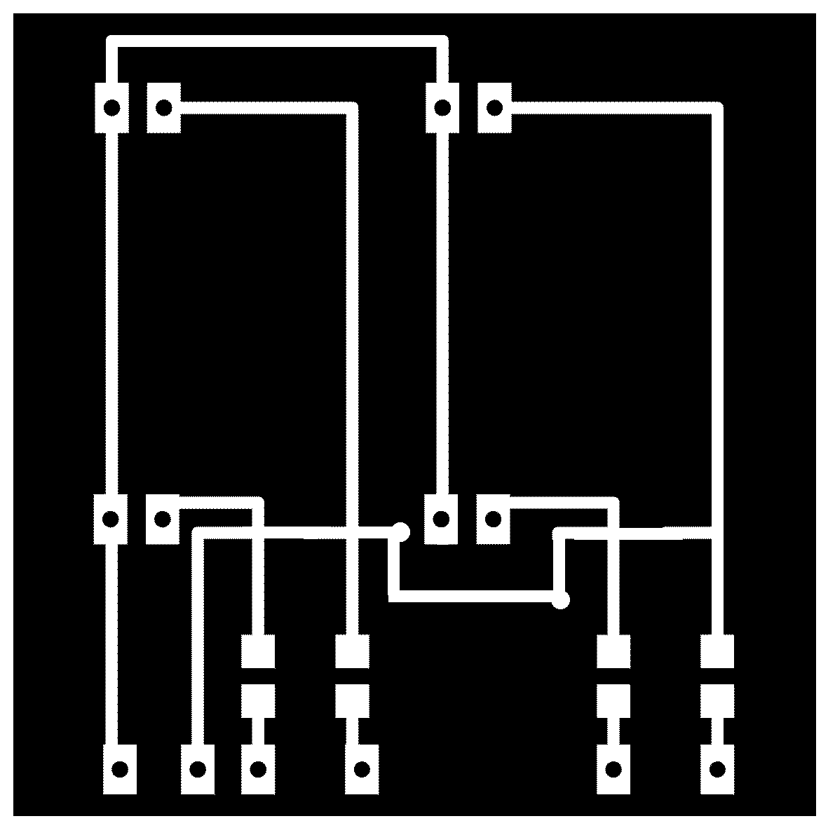
 17-Do an all-integrated circuit (fail)
These is the board were everything is integrated (micro-processor, multiplexer, voltage divider circuit for 9 input, ...)
17-Do an all-integrated circuit (fail)
These is the board were everything is integrated (micro-processor, multiplexer, voltage divider circuit for 9 input, ...)
 It should work but it don't ! The traces are so thin that they always get damage. It could probably work with an other process (laser?, smaller drilling tool ?) so here are the eagle files
18-Do a shield for my 'cosmino' (fail)
I tried to simplify it by doing a shield for my board that was already working.
It should work but it don't ! The traces are so thin that they always get damage. It could probably work with an other process (laser?, smaller drilling tool ?) so here are the eagle files
18-Do a shield for my 'cosmino' (fail)
I tried to simplify it by doing a shield for my board that was already working.
 Fail again because the SMD chip for the multiplexer I used is very very small.
19-Change the SMD multiplexer for a bigger one and design it in eagle, do the shield again
I found the same chip in an other package on digikey. It was bigger so easier to sold, but it didn't exist in any libraries. So I had to design a new parts in eagle and add it in my own library. eagle files
Fail again because the SMD chip for the multiplexer I used is very very small.
19-Change the SMD multiplexer for a bigger one and design it in eagle, do the shield again
I found the same chip in an other package on digikey. It was bigger so easier to sold, but it didn't exist in any libraries. So I had to design a new parts in eagle and add it in my own library. eagle files
 Electronic & digital fabrication, done ! Let's start with the interface.
20-Generate a 3D model of the board and the parts
I decided to create my geometry directly in processing because importing a obj files made with rhino was sometimes working and sometimes it cause a crash to my graphic cards ... I did only cylinder (wich was not that easy !) because they were close enough to the physical model so the magic was working.
Electronic & digital fabrication, done ! Let's start with the interface.
20-Generate a 3D model of the board and the parts
I decided to create my geometry directly in processing because importing a obj files made with rhino was sometimes working and sometimes it cause a crash to my graphic cards ... I did only cylinder (wich was not that easy !) because they were close enough to the physical model so the magic was working.
tangik from hugo moissinac on Vimeo 21-Improve the code I create a small interface, create a reset function and some other usefull stuff. But the hardest part was to recognize if 4 joints for an horizontal part are at the same level, so the software generate the horizontal part despite it don't have resistors inside. All my code was propper because if I wanted to use 16, 32 or more input and more pieces I just needed to change 2 value in the setup and the rest was following. But for that one I couldn't manage to find a clever way (and miss time) so I just write one by one all the possibilities in the code. Still lot to do, but already something ! Check the final presentation. Final bill (for 18 pieces) : Part number following when necessary -27 RCA single switch female connectors PJRAN1X1U04X: 13$ -1 double sided copper board: 10$ (really ?!) -40 Resistors : 1$ -18 RCA male connectors : 3$ -100? single connectors : 2$ -Wires (1 meters ?) : 1$ -Analog multiplexer : 2$ -PLA for 3D printing : 2$ ? -Very small amount of epoxy : 0.1$ -Trash wood : 0$ TOTAL : 34$ ... And a cosmino (fabkit) and a computer to run the interface ... But that's more prerequisites than part of the project !