2016
Embedded programming Mar 16. 2016
This week we started to program our microcontroller board that was made two weeks ago. First task was to study the datasheet of ATtiny44A. ATtiny44A is a low-power CMOS 8-bit microcontroller based on the AVR enhanced RISC architecture. By executing powerful instructions in a single clock cycle, the ATtiny44A achieves throughputs approaching 1 MIPS per MHz.
Other things found in the datasheet are:
- Architectural overview as well as detailed description of different elements of the device.
- ALU, memories, clock system
- Pin configuration and description.
- Different modes of operations (power management)
- Resets and interrupts
- IO ports and operations
- Counters and timers
- AD converters
- Debug system
- Programming
- Electrical characteristics
- Performance characteristics
- Simple code examples that briefly show how to use various parts of the device.
- Summary of the instructions set
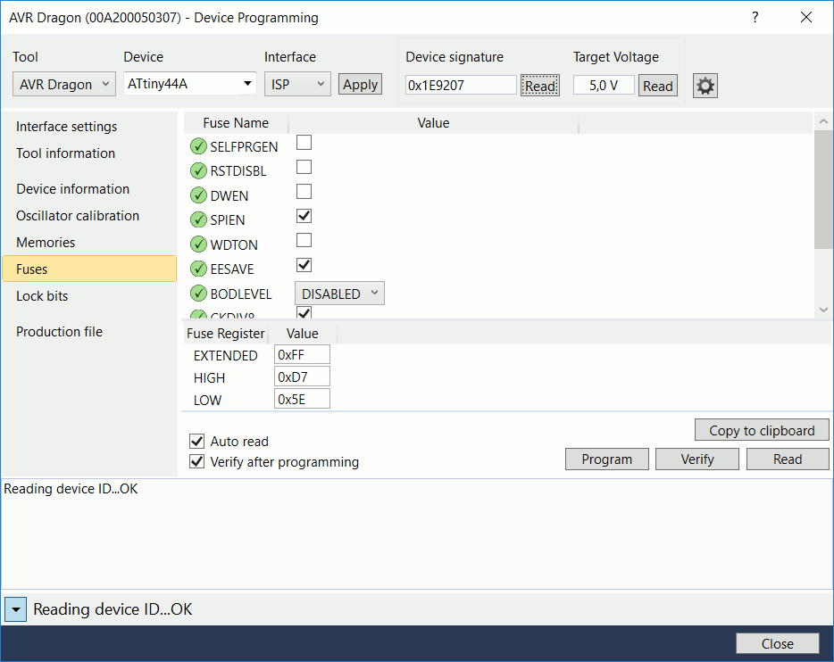
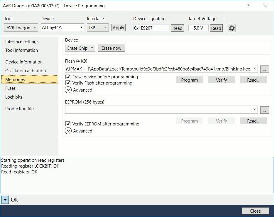
Fist problem that I faced when I started to program was that my FabProgrammer was not recognized by my laptop. First, I thought that it was my operating system Windows 10. Therefore I started the programming with AVR Dragon which integrated well with Atmel Strudio 7. I programmed the Hello FTDI.44 example and programming was successful. Programming the fuses was also possible as shown below. You need to select Tools and Device programming. Once the device programming window opens, define the interface settings; select the programmer and the chip (ATtiny44A) and hit Apply. After that, you are able to read device signature and target voltage. If Atmel studio reports that the device cannot enter into programming mode, check the reset line voltages during the programming. I had short circuit and the programmer could not control the chip.

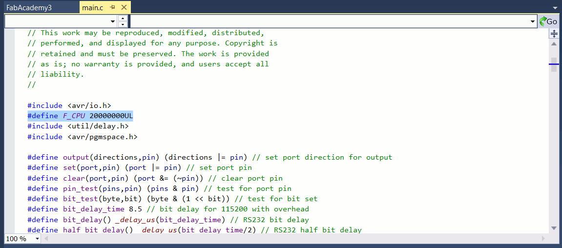
In order to program the serial Hello world, we needed to add the used clock freq into the code. shown below.
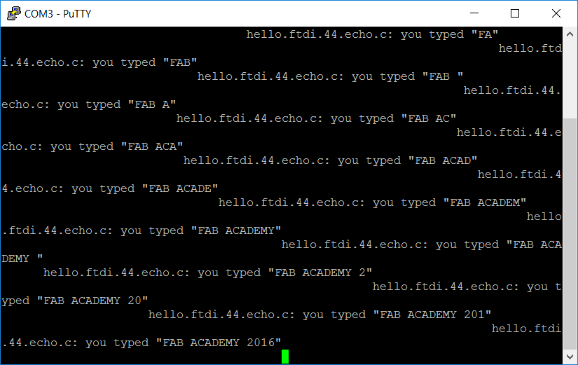
Correct baudrate for echoing the terminal text is 115200. First, I used 9600 and the characters did not come through correctly even though some activity was present.
Here is the correct connection of cables..
Next, I started to debug my ISP programmer and no fault was found. Suddenly the computer recognized it both in Linux and Windows10 and the driver was also successfully installed from Adafruit to Windows 10. I was able to program the target board with my ISP programmer but next day the programmer was dead again and no matter what I tried, I was not able to revive the programmer. I need to build a new one when a suitable time is found. At least I was able to verify the functionality under Windows 10.
I also tested Atmel ICE programmer which works similar to AVR Dragon as ISP programmer. Here couple of example codes of turning led on and off with different time delays. I found the code here and here.
#include <avr/io.h>
#include <util/delay.h>
int main (void)
{
// set PB2 to be output
DDRB = 0b00000100;
while (1) {
// short flash
PORTB = 0b00000100; // set PB2 high
_delay_ms(200);
PORTB = 0b00000000;// set PB2 low
_delay_ms(200);
// long flash
PORTB = 0b00000100;// set PB2 high
_delay_ms(2000);
PORTB = 0b00000000;// set PB2 low
_delay_ms(2000);
}
return 1;
}
int main(void)
{
DDRB = 0b00000100;//Makes 2nd pin of PORTB as Output
DDRA = 0b01111111; //Makes 7th pin of PORTA as Input
while(1) //infinite loop
{
if((PINA & (1<<PA7))==0) //If switch is pressed (Normally active)
{
PORTB |= (1<<PB2); //Turns ON LED
_delay_ms(1000); //1 second delay
PORTB &= ~(1<<PB2); //Turns OFF LED
}
}
}
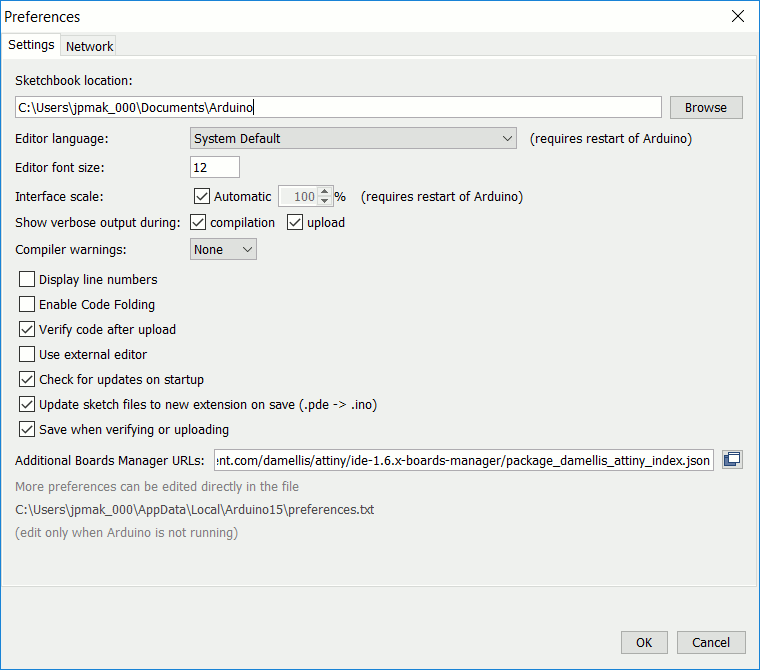
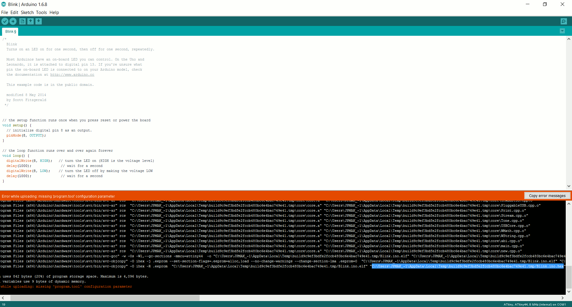
I also tested Arduino IDE but was not able to get AVRDragon nor Atmel ICE to work as a programmer straight from Arduino IDE. I followed Charles Fracchia’s site but no luck. I found a workaround from Instructables that uses Arduino IDE generated hex files and uses Atmel Studio to flash it to ATtiny. What you need to do is to turn on showing verbose output in Arduino IDE which reveals the location of the generated hex code. This can be flashed into the chip with Atmel Studio.
You can edit Arduico preferences.txt file to change the location of the hex file.
I tested the led blink example sketch and changed the pin according to my board. I was not able to set the clock frequency correctly. The led blinking was slower than anticipated. For this, we can easily change the clock rate in boards.txt (add a new entry) if you want to program with a hardware programmer. For AVR328 running at 20MHz, we can add the following to the boards.txt:
pro328_20.name=Arduino pro 328 20mhz
pro328_20.upload.protocol=stk500
pro328_20.upload.maximum_size=30720
pro328_20.upload.speed=56000
pro328_20.bootloader.low_fuses=0xFF
pro328_20.bootloader.high_fuses=0xDA
pro328_20.bootloader.extended_fuses=0×05
pro328_20.bootloader.tool=avrdude
pro328_20.bootloader.path=atmega
pro328_20.bootloader.file=ATmegaBOOT_168_atmega328_20.hex
pro328_20.bootloader.unlock_bits=0x3F
pro328_20.bootloader.lock_bits=0x0F
pro328_20.build.mcu=atmega328p
pro328_20.build.f_cpu=20000000L
pro328_20.build.core=arduino
pro328_20.build.variant=arduino:standard
pro328_20.upload.tool=avrdude
The file resides in C:\Program Files (x86)\Arduino\hardware\arduino\avr
There are also possibility to download ATtiny support for Arduino which has the possibility for ATtiny44a 20 MHz. You can Google “Programming an ATtinyw/ Arduino 1.6” to find instructions to do this.
I took the Example file Blink from Arduine IDE and changed the pin 13 to pin 8 that corresponds to the location of the led on my board.
Files: See the code above