2016
Electronics Production Feb 17 2016
This week, the task was to make an in-circuit programmer.
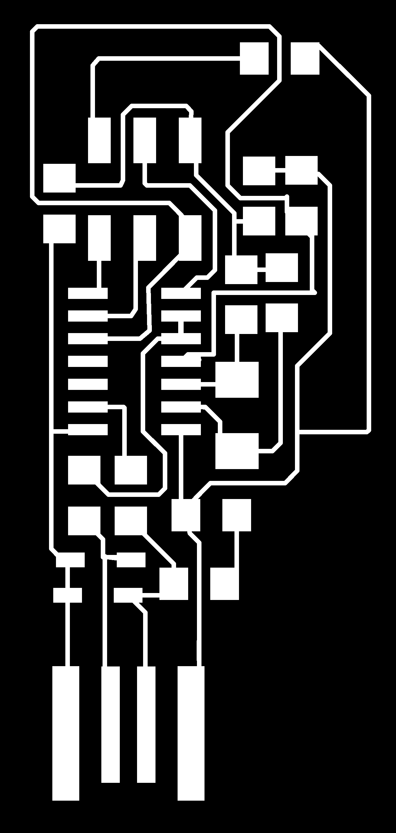
We decided to do Valentin’s version of the programmer.


We did a joint work with Dorina and Antti and first experimented first with Roland MonoFab. We only had FR4 PCB material in stock. First we tested with outline routing with 1/64 bit that our stock was flat and all the copper was routed away with the selected routing depth. Once the depth was verified, routing of the traces was performed. The quality ot the routing was not good as seen in the picture. We even changed the bit to brand new one and the result was the same. It might be that FR4 was the reason and FR1 would result good traces. The traces can be cleaned with some sanding.
We changed to LPKF V-shape bit that has been used extensively by our proto shop. The profile for the cut is shown here.

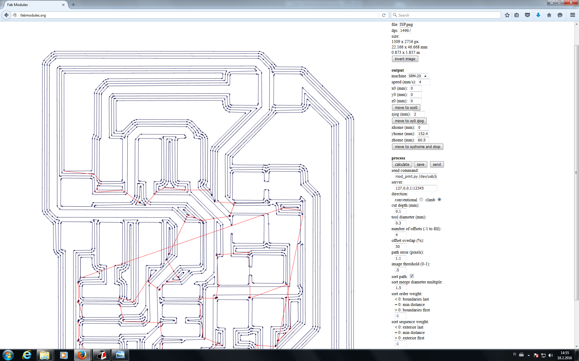
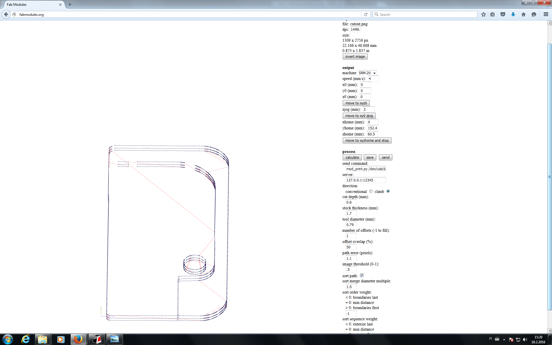
Bellow is the Fabmodules.org settings for this bit that worked nicely. The cutout settings are also shown. The cutout was done with 1/32” endmill.


The result of the cut is absolutely beautiful. Now nasty burr whatsoever. Next it was time to deploy the components to the board. The only problem would be non-flat bed of the milling machine.
I started wtih 0 ohm resistor from the breakaway portion of the board. First soldering one pad and then placing the component to the board and heating the solder together with the component to make an initial contact. Then soldering the other end.
Everything went fine until I started to cut corners and started to put solder to all the pads of a single component. It is very difficult to level the component when there are more than one pad covered with solder. This is especially true with the microcontroller. Next microscope picture shows how one leg of the microcontroller is hanging with no galvanic connection to PCB. There were actually couple of such soldering mistakes that prevented programming of the board. The soldering tip was a bit thick for such work but with de-soldering braid, I was able to fix the problematic connections. Also, it was very important to clean the soldering tip with a sponge between the components. How these faults were noticed, was when it was about time to program the programmer (see down).
Programming
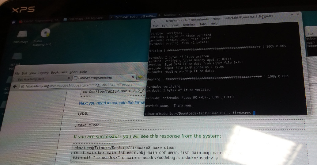
For the programming I decided to follow Linux approach even though I usually use Windows. Therefore I decided to use USB bootable Xubuntu distribution and used PenriveLinux to make such USB stick. After that it was simple to follow instructions from Fab Academy tutorials.
As a programmer, I used Jani Ylioja’s Fab ISP programmer done during Fab Academy 2015. These are the command needed for programming the programmer
Installation of the Linux environment:
sudo apt-get install flex byacc bison gcc libusb-dev avrdude
sudo apt-get install gcc-avr
sudo apt-get install avr-libc
pico Makefile (edit the file to uncomment the line with usbtiny)
make clean
make hex
make fuse (this is the place where non-functioning board is identified, there are errors if the board is not working properly.)
make program
As a result, we have a working ISP programmer to be used in two weeks from now.

Here is the ribbon cable that I also made.
Files: None produced