2016
Computer-conrolled Cutting Feb 10 2016
This week, the task was to design, make, and document a parametric press-fit construction kit and use vinyl cutter to cut something in order to get familiar with the cutter.
Experiment 1
First thing I did was so called Plus-Plus toy to test how to do laser cutting and how accurately I can do the pieces with using only Inkscape and cloning function presented in the lectures.
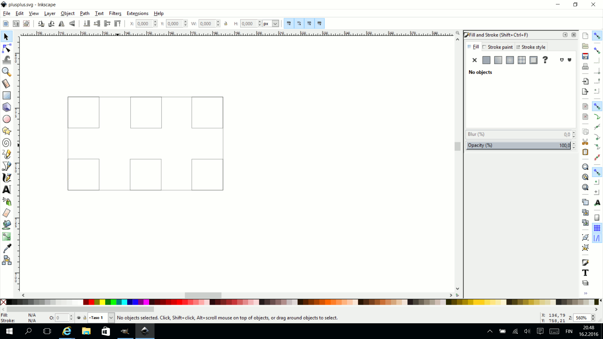
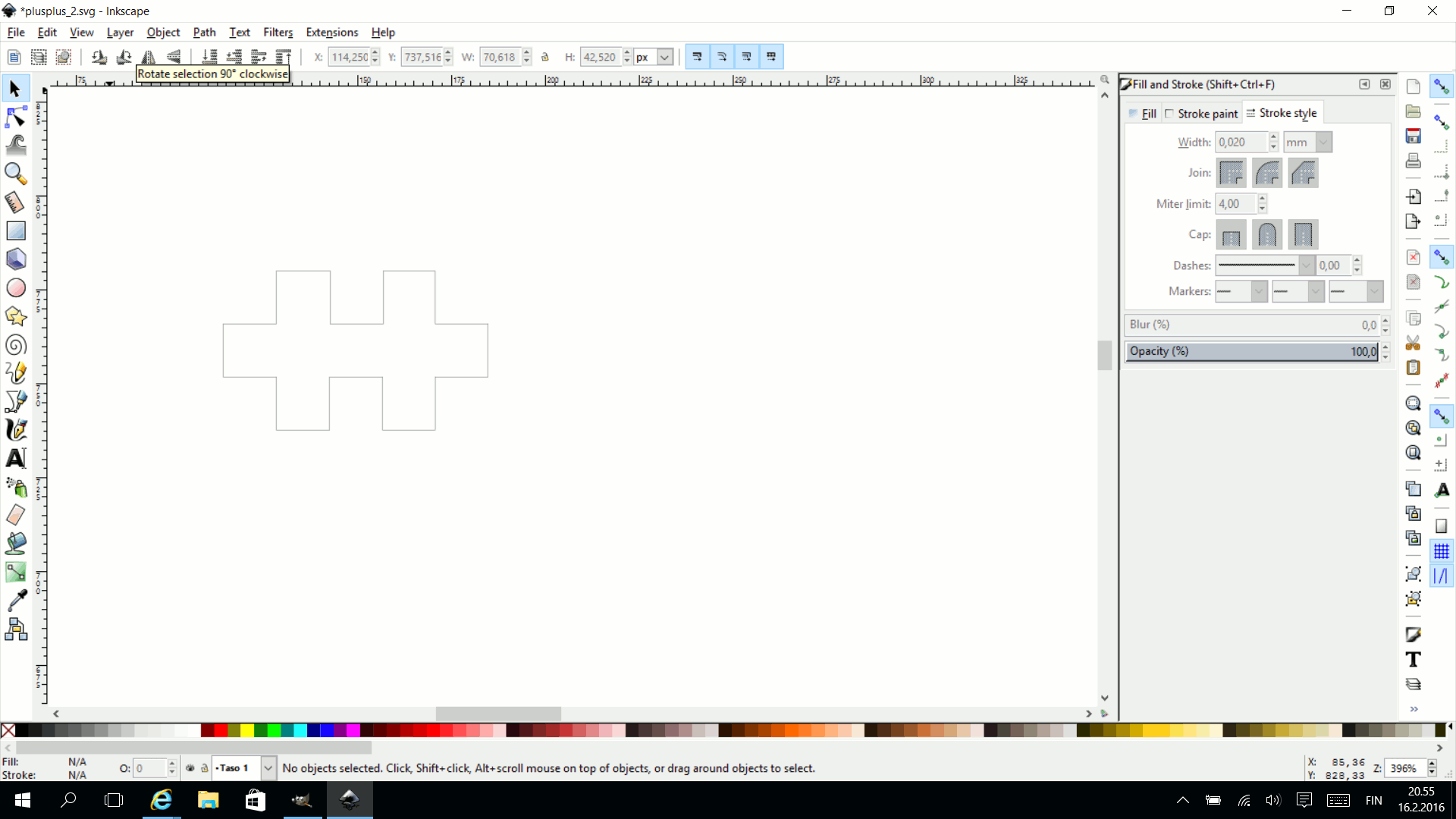
I constructed an Inkscape model from a measured Plus-Plus piece, First, I draw a 20mm x 12mm rectangle and placed six cloned (Alt-D) 4x4mm squares as shown bellow. Then, I performed Path-Difference command for all the squares individually by selecting the rectangle and one square at a time by holding shift key when doing the selection. The Difference command needs to start fro the origin of the cloning. Also, if you need to change the size of the square, you need to have the original file. Inkscape does not hold history as e.g. Solidworks or Inventor does. The next image shows the outcome of this operation.


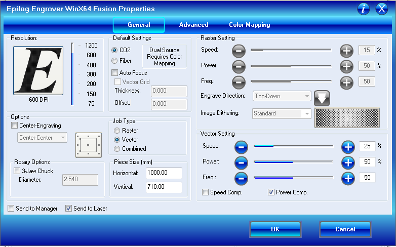
In order to use this model as an instruction for lase cutter, we need to save it as a pdf file. Laser driver recognizes a line width 0.02mm as cutting trace. Since there is no raster image in this image, the laser cutter is only cutting. We used 4mm transparent acrylic for our sample piece.
Result:
Laser cutter is CO2 Epilog Laser Fusion 75W. I used the manufacturer provided driver. Initial measured dimensions of the Plus-Plus piece produces slack joints. Therefore I modified the cut dimensions 0.1mm smaller which produced a nice tight fit, The attachment might be to tight for child to play but connection is strong. The blue piece is the original mode
Laser cutter setup:
You need two setup the coordinate XYZ for the laser depending on the material thickness and location of the laser cutting / engraving.
- Focus: Select the Focus with up down arrows and place the focusing tool hanging to the moving lens assembly. Rise the laser bed with joystick controller so that the focusing tool is just touching the surface of the processed material. Zero the focus by pressing the control stick downwards (not direction down).
- Set XY coordinate zero buy selecting Jog with up down arrows. Move lens head with the joystick and once in desired place, zero by pressing the joystick downward. Upper left corner of the document is the the zero point in XY by default. There are other options as well.
- Once these are done you need to make pdf out of your e.g. Inkscape design and print using Epilog printer driver (below)
- You can see the manufacturer recommendations for speed and power settings for different materials and we have also saved some settings behind the Advanced tab.

Experiment 2
The second example was a laser cut cardboard table. I used Solidworks to make the design. The legs are depicted in the figure bellow.

The main feature used in the Solidworks was the Pattern tool in circular and curve driven modes.
Here is the drawing procedure for table top and additional shelves:
Sketch a circle
Extrude 4mm
Sketch Center Rectangle
User Smart Dimensions to make it correct size
Make Extruded Cut of the rectangle
While the extruded slot is selected, use Circular pattern to multiply the slot evenly spaced along the circle edge.
Save the part.
Similar procedure is used for legs but now with Curve driven option.
In order to make the Solidworks models usable for Laser cutter (pdf file), I used the following steps using Solidworks and Inkscape:
Open New drawing in Solidowrks and select a preferred part as drawing.
You can delete Sheet Format.
Check the scale of the drawing. Right click and properties.
Save the drawing as DFX file. I also tried Adobe Illustrator file but was not successful to make the import to Inkscape. This might work but I was in a hurry and had no time to debug.
Import the DFX file to Inkscape using the scale that is used in the DXF file.
Set the line width to 0.02mm for lase cutting and save the file in PDF format.
Average thickness of the cardboard used was 4.8mm. The following setup was used in Epilog. The settings were bit light and we ran the program twice to make sure that the parts were properly detached.
The final product loks like this:
The lowest plate was too big making first of all the installation difficult and second, the parts were not perfectly seated. If more dense material is to be used, this needs to be fixed. The reason for non-precisely made plate was that I could not figure out how to use measure tool in Solidworks. In my opinion, Inventor or Autocad has more intuitive tool for measuring spaces between elements.
Vinyl Cutting
I tested vinyl cutting from Inkscape. One difficulty was finding the origin. Sometimes the cutting started around 80 cm from the edge of the vinyl roll. This was due to not setting the length of the page equal to the page the machine thinks it has. Roland driver has a feature that can ask what machine thinks about the length of the vinyl piece. You should either put the inkscape page size equal to these values or put the values from Inkscape as page size to Roland vinyl cutter preferences. Another thing to remember is to put length longer than width. If it is the other way around, the print might come vertical.
Steps for vinyl cutting:
- Place the vinyl sheet according to the manual depending on the width of the roll or sheet.
- With up and down arrows on the user panel of the cutter select EDGE and press EDGE button. The machine finds the “lower” edge of the sheet.
- Open Inkscape and make drawing and text and print. Lower left corner is the origin.
- Make sure that you do not get the paper size from the machine. Enter the sheet size from Inkscape to the printer driver paper size.
- Draw a box around your design to make it easier to separate from a big sheet of vinyl. You can even make double frame box.
- You can use transfer adhesive sheet to transfer separate letters and parts of letters to the final destination of the sticker. Below, I made it letter by letter with tweezers.