2016
Input Devices Apr 13. 2016
This week we made input device that measured something. I started to build a LSM303C based accelerometer and orientation measurement device. LSM303CTR is a 6 degrees of freedom (6DOF) inertial measurement unit (IMU) in a single package. It houses a 3-axis accelerometer, and a 3-axis magnetometer. The range of each sensor is configurable: the accelerometer’s scale can be set to ±2g, ±4g, ±6g, or ±8g, and the magnetometer has full-scale range of ±16 gauss. The LSM303CTR supports I2C and SPI. I chose to use I2C because there were code available for that. Another way would have been to use SPI ports found in ATtiny45 There are also examples found for Arduino. I’m hoping to get the code by Neil edited for the LSM303CTR.
First challenge is to produce a PCB that can hold the LSM303CTR chip which is in very tiny land grid array package (LGA). DRC rules in Eagle has to be set to around 10 mil and we have router bit that cuts around 22 mils. It is going to be interesting to see how much copper will be left on the pads for the component after the milling process.
I found a good tutorial of the LSM303CTR in DigiKey website given by Sparkfun. The Eagle model is also available and can be found from Adafruit as Adaftuit_digitalIC.lbr
I also decided to make two boards; one for the sensor and one for the ATtiny45 microcontroller. Below are the schematic and traces designs for the boards,


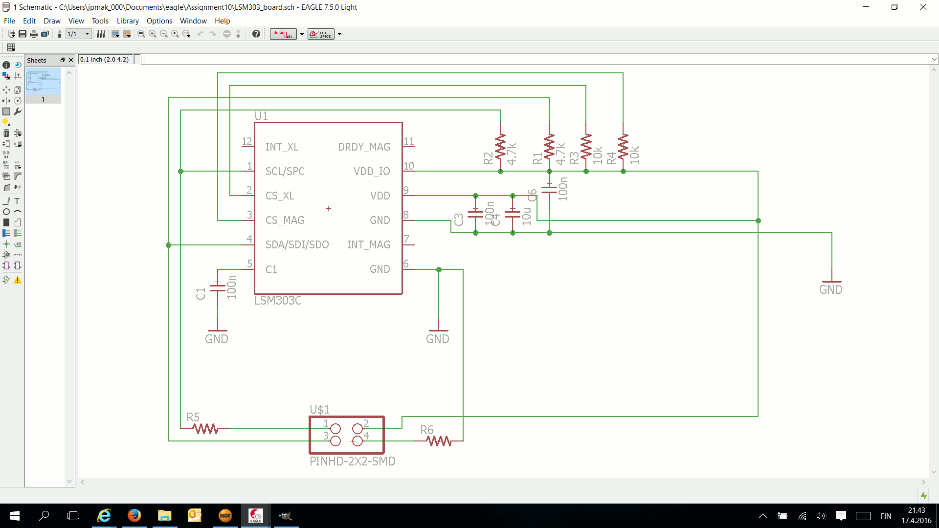
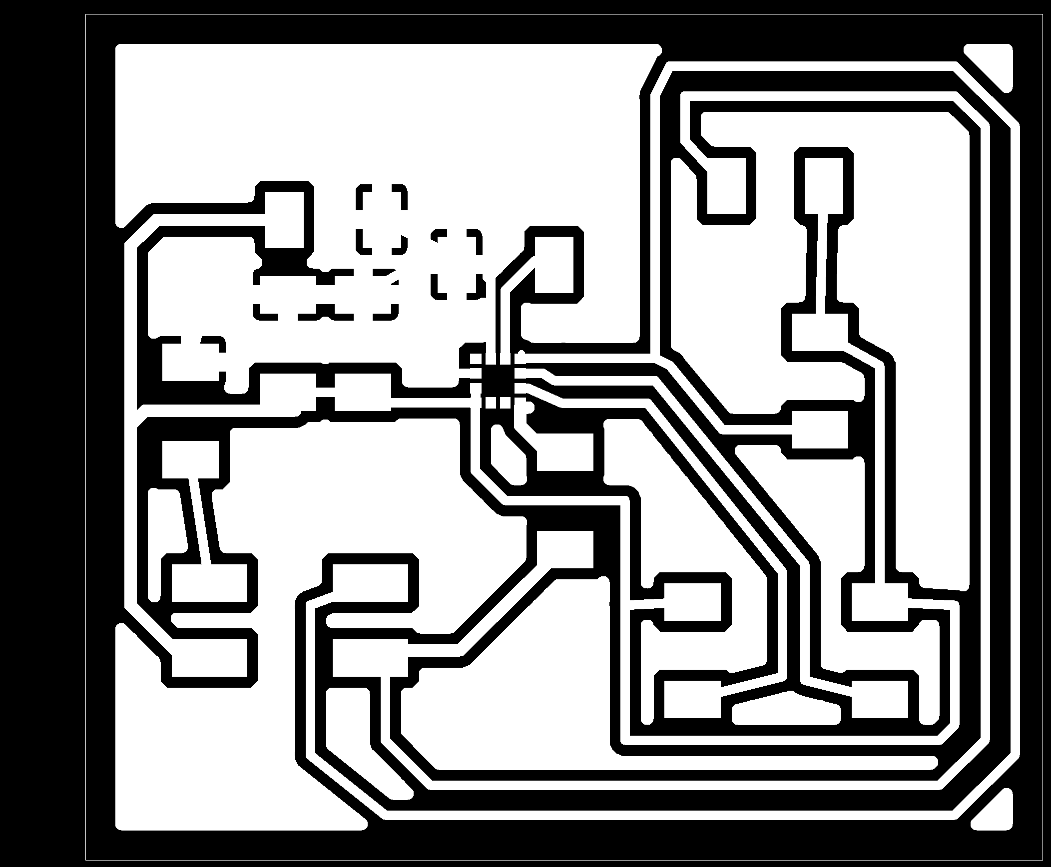
As expected, the footprint of the sensor was too small for our milling process with 0.3 mm bit. It would require 0.13 mm router bit to have fabmodules to make toolpaths that would isolate the pads of the sensor. I tried our 0.3 mm V bit but it left only very thin pads which were too tricky to spread paste onto. That is why I needed to ditch the idea of using the LSM303CTR for the time being. I will get back to it when I have extra time.
Next, I designed a board for Hall sensor as well as light transistor and the schematics and PCB milling files for these are shown below. I used the same structure as found in the Hello files but separating the sensor onto a different board.
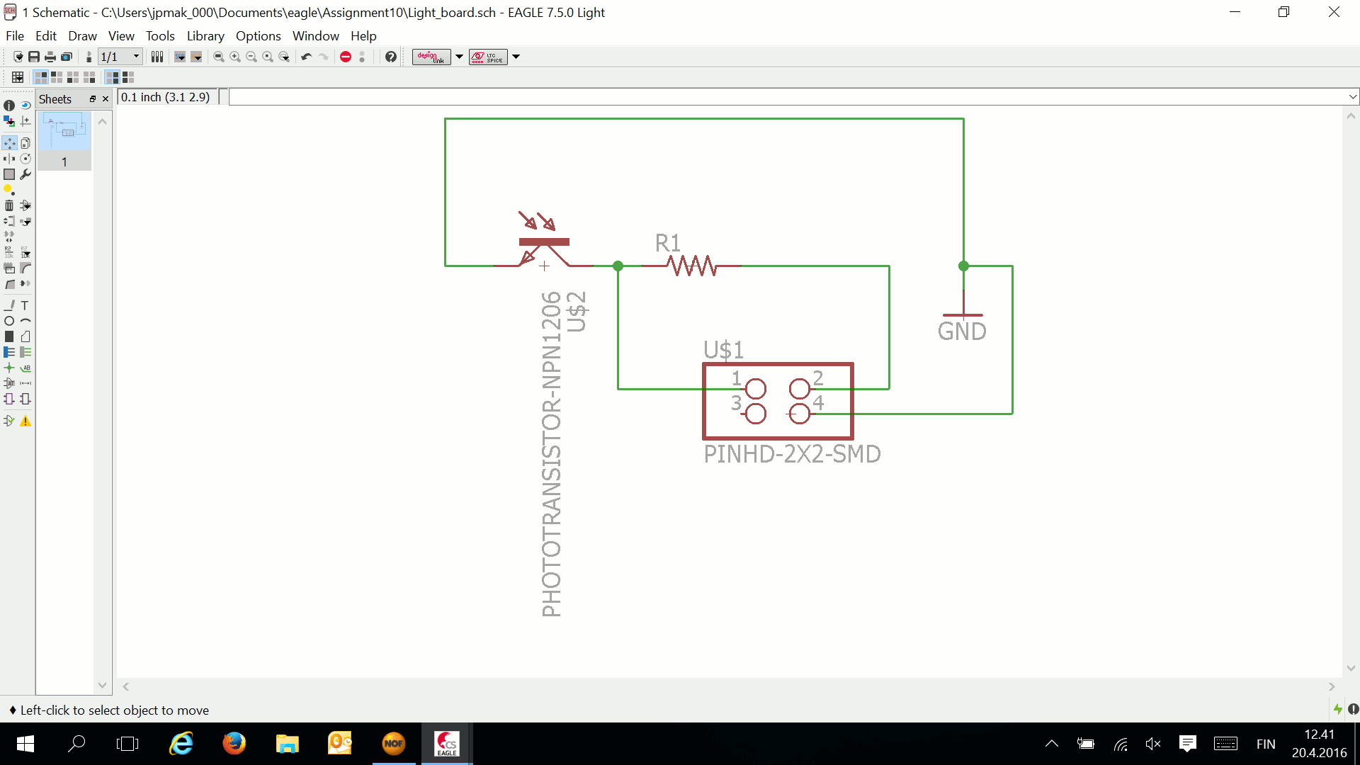
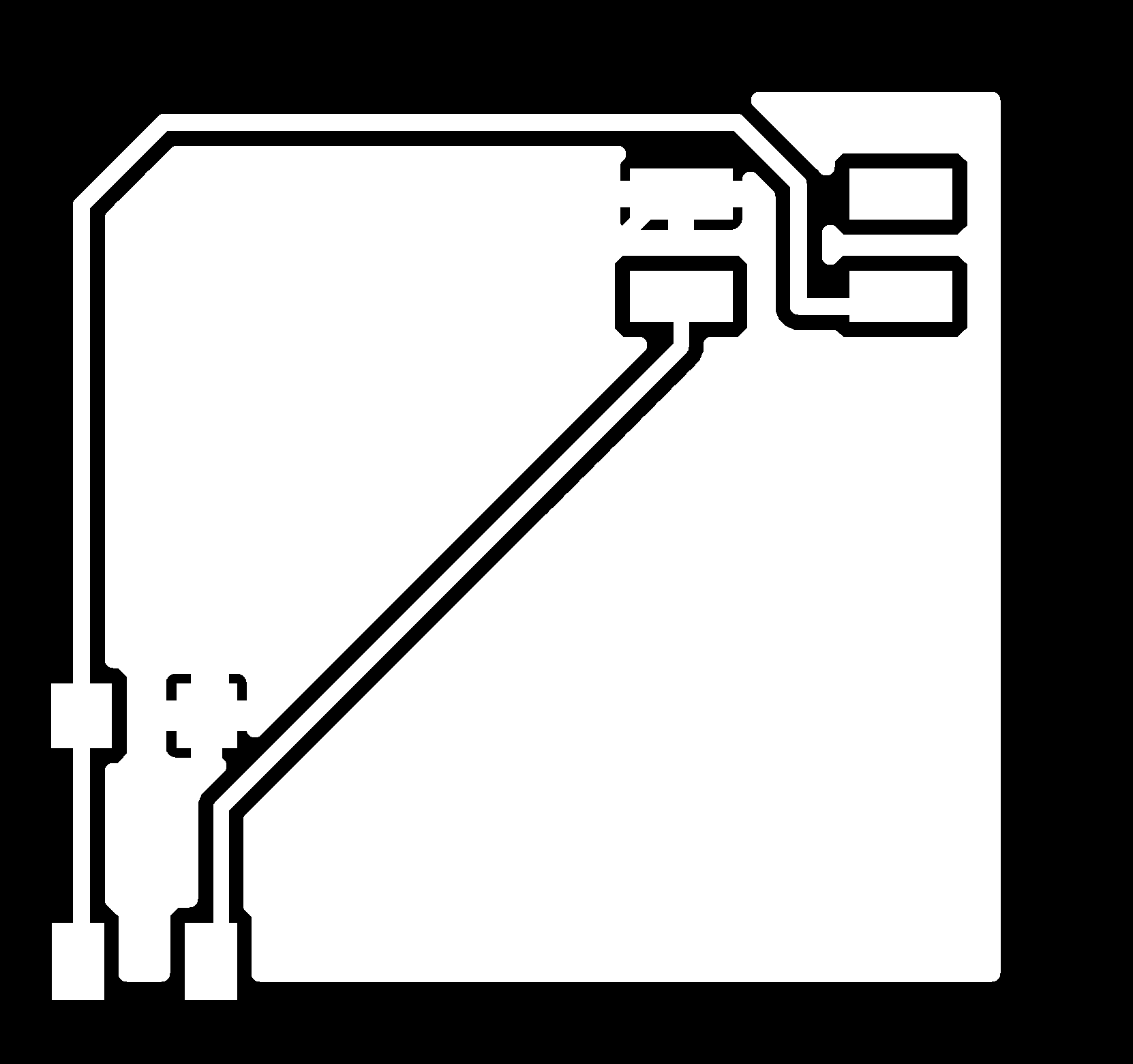


The connections between the sensor board and the microcontroller motherboard is shown here. I used 10 wire ribbon cable but only 4 wires connected.
Light sensor connected
Hall sensor connected
Next I copied the microcontroller C code as well as python codes by Neil for these two sensors form the Fab Academy site. I used Atmel Studio 7 and AVR dragon to program the ATTiny45 microcontroller.Default fuses were ok since default internal clock 8 MHz was used. Only thing that you need to ad was F_CPU=8000000 either as definition in the C code or into Atmel Studio Project Preferences-Toolchain-Symbols section. I used the later one and no changes to the code was required. See the usage of Atmel studio on Assignment 8.
I switched to Linux for testing the functionality of the sensors. I used the python script and ran it with command
sudo python hello.mag.45.py /dev/ttyUSB0
If there is packages missing, you can install them with command
sudo apt-get install <missing package>
I needed to install python-tk and python-numpy might also be needed.
Here are some captures of the results:
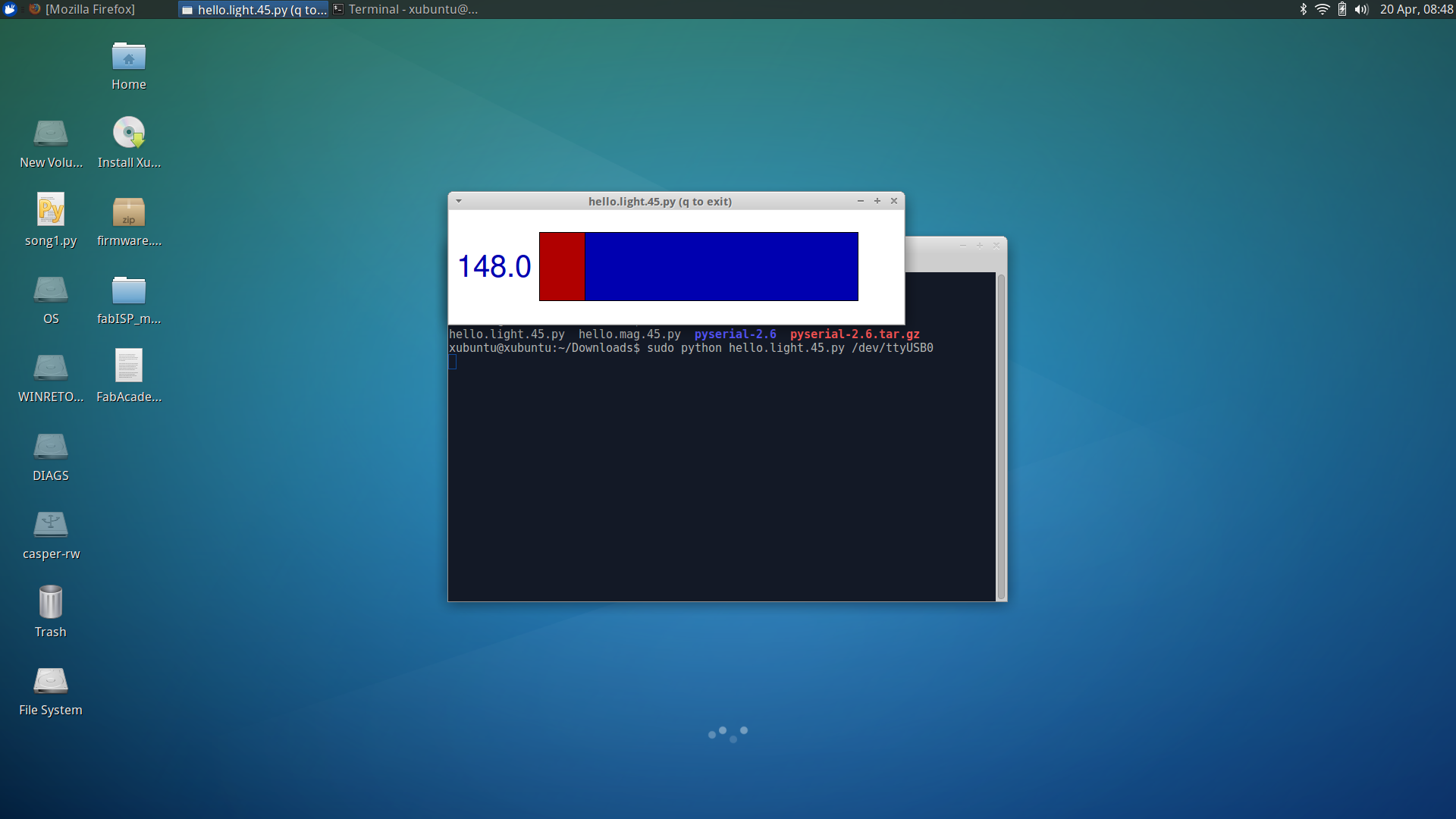
Light
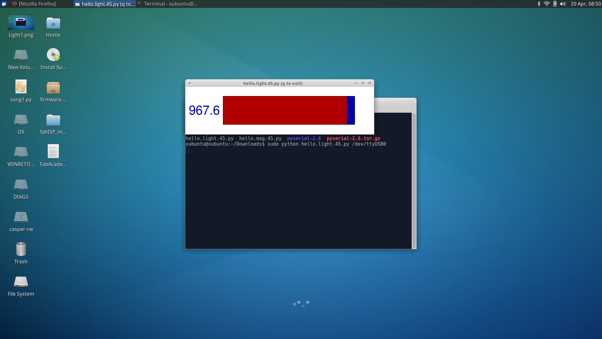
Dark

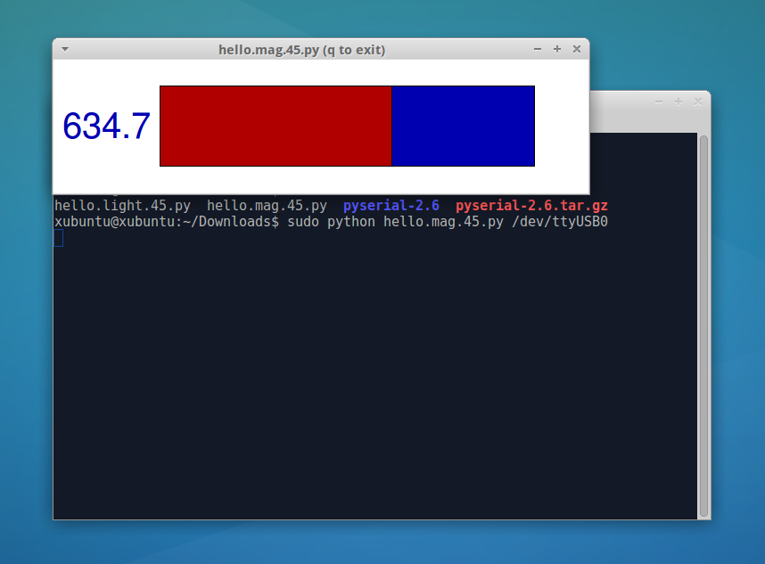
No magnet near by
Magnet touching sensor