Electronic production
Milling, testing and programming of a PCB
Quick reminder of this week assigment :
Electronics Production :
Learning outcomes:
Have you:
----------------------------------------------------------------------------------------------------------------------------------
What I have done?
This week was full of surprises.. When I have first read the program, things were crystal clear :Pretty simple isn't it?
Sadly, things were not that simple.
Part 1 : Select a design
This part was quite easy, after looking on internet and asking few questions to Thomas, i found one!
Tuto
It's an complete tutorial, including the programmation part.
Part 2 : Milling the design on a PCB
Things went downhill from here...
Our group in Bruxelles experiments some issues with the order of both the milling machine and the components.
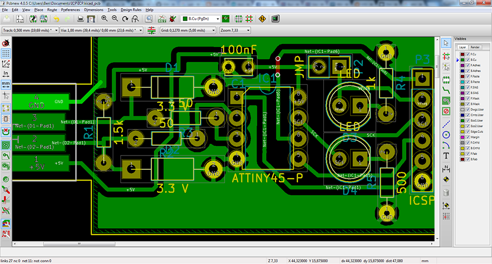
Thanks the help of a friend who was in the lab, I have played a little with Kicad, a Cross Platform and Open Source Electronics Design Automation Suite.Kicad and designed a variation of the reference circuit. You will find all the files in the source section
We found a workaround to access a machine but it was not as efficient as having the machine around us. We have lost a lot of times because of that
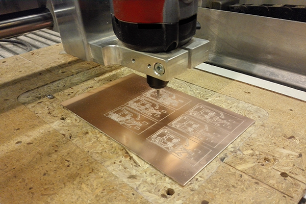
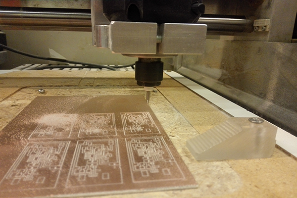
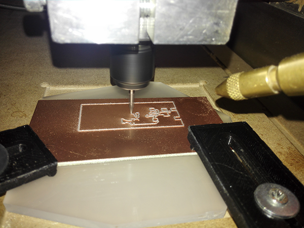
You can see our first tests in the pictures below :
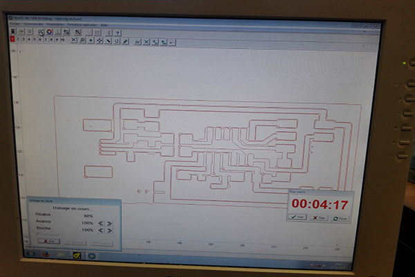
I have discovered then that the design was not the correct one, it was meant to use smaller components and was not the one from the tutorial. So wrong designs + wrong components = lots of issues.... The components were not made to be solder by humans (the pins were under the chip) and the design was utterly complicated (quartz not needed....)
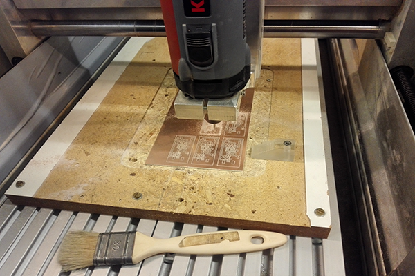
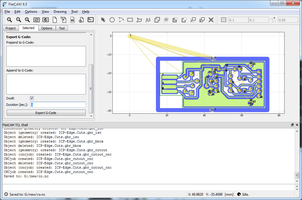
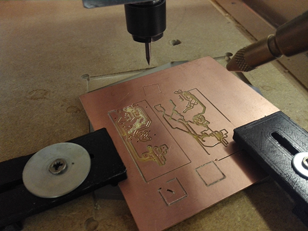
Today, (the 21) we finally managed to use our own CNC and engrave our pcb with the correct design, not without a lot of trial and error. We manage to do that thanks to FlatcamFlatcam , a software who can produce G-code (used by the CNC) from a gerber file (produced by software like kicad or eagle).
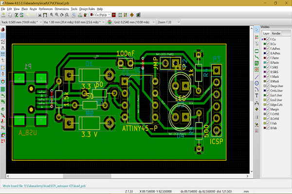

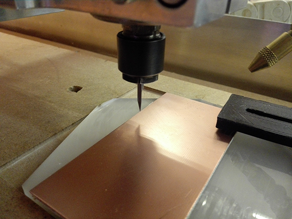
The main challenges were to get the correct mills (The design was made with 0.2mm in mind and we can't achieve better than 0.4mm trace. So back to flatcam and Kicad to enlarge it!) and achieve something that we can solder. The milling of the holes was problematic because of the mill again (it remove to much copper from the pcb). We were using a mill of 0.2, a flat mill 0.8 and the pcb was FR-01.
You can see in the pictures the different steps and evolution.

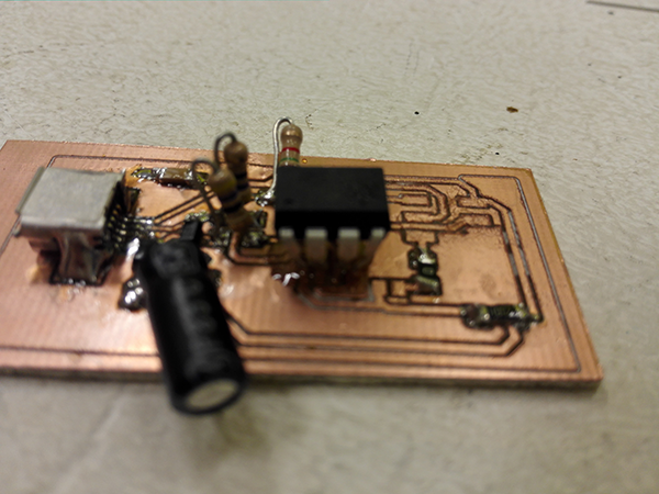
We are finishing right now the first successful (crossing fingers here) PCB and we will test it during the week in order to finish the testing and programming part
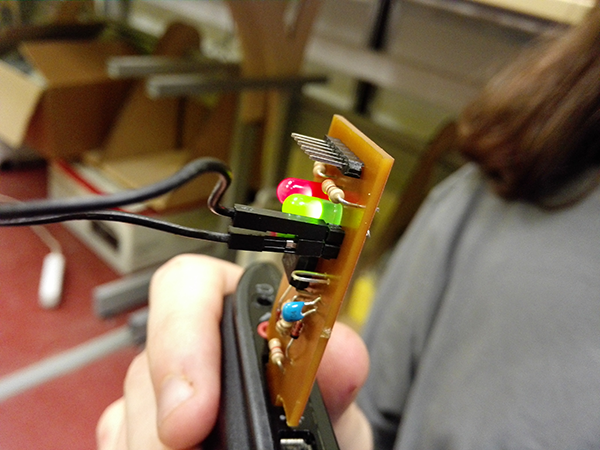
It's working but the board is not clean enough and we have sometimes short-circuits. We will retry with the correct mill asap.
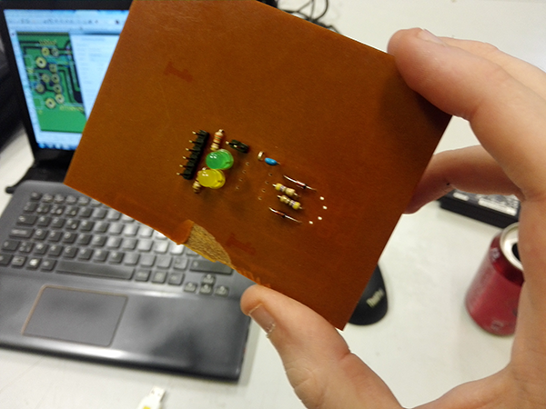
3) Test and program the board UPDATED
Once the second board complete and finished, it was time to programm it. I have follow the tuto
The installation of Atmel GNU, GNU make and avrdude were really easy, mostly point and click and a simple update of my windows path as described in the tuto
My first issues begin with the zadig drivers (2.3 versions) :
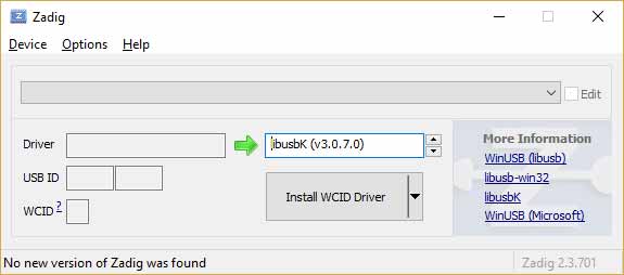
That was only the beginning of my misadventures : I was getting all the error messages from the tuto and more...
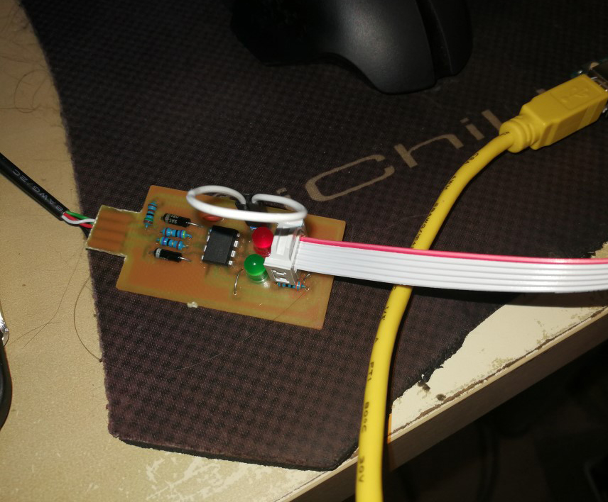
I have finally tried the combo arduino uno + fabISP with the pin 10 on the reset of my tinyisp but it wasn't the complete solution : the makefile was not correct
I have modified the "programmer?=" with Arduino and modified the command by adding the parameters (COM port and 9600 as baud rate) with the help of a friend.
# Generic AVR Makefile - Adapted for FabTinyStar
# Brian Mayton <bmayton@media.mit.edu>
#
# 'make' builds the .hex file.
# 'make flash' uses the programmer to load it onto the target chip.
# 'make fuses' programs the fuse bits on the target chip.
# 'make rstdisbl' blows the reset fuse.
# 'make clean' removes all autogenerated files.

# OBJECTS should list all of the object files for the program (e.g. for each
# .c file, list a corresponding .o file here.)  APPLICATION just specifies the
# name of the hex/elf files, and can be whatever you want.
OBJECTS = main.o usbdrv/usbdrv.o usbdrv/oddebug.o usbdrv/usbdrvasm.o
APPLICATION = fts_firmware

# Set up which MCU you're using, and what programmer, and the clock speed
# here.
MCU = attiny85
PROGRAMMER ?= arduino
F_CPU = 16500000UL

# Fuse bit settings
EFUSE=0xFF
HFUSE=0xDD
LFUSE=0xE1

# Fuse bit settings with reset pin disabled
HFUSE_RSTDISBL=0x5D

# Edit these if you want to use different compilers
CC = avr-gcc
OBJCOPY = avr-objcopy
SIZE = avr-size
AVRDUDE = avrdude

# Compiler and linker flags
CFLAGS=-mmcu=$(MCU) -Wall -DF_CPU=$(F_CPU) -I. -funsigned-char \
	-funsigned-bitfields -fpack-struct -fshort-enums -Os -Iusbdrv
LDFLAGS=-mmcu=$(MCU)

all: $(APPLICATION).hex

clean:
	rm -f usbdrv/*.o
	rm -f *.hex *.elf *.o

%.hex: %.elf
	$(OBJCOPY) -j .text -j .data -O ihex $< $@

$(APPLICATION).elf: $(OBJECTS)
	$(CC) $(LDFLAGS) -o $@ $^
	$(SIZE) -C --mcu=$(MCU) $@

%.o: %.c
	$(CC) $(CFLAGS) -c $< -o $@

%.o: %.S
	$(CC) -x assembler-with-cpp $(CFLAGS) -c $< -o $@

flash: all
	$(AVRDUDE) -p $(MCU) -c $(PROGRAMMER) -P COM8 -b 9600 -e \
		-U flash:w:$(APPLICATION).hex

fuses:
	$(AVRDUDE) -p $(MCU) -c $(PROGRAMMER) -P COM8 -b 9600 \
		-U lfuse:w:$(LFUSE):m -U hfuse:w:$(HFUSE):m \
		-U efuse:w:$(EFUSE):m

rstdisbl:
	$(AVRDUDE) -p $(MCU) -c $(PROGRAMMER) -P COM8 -b 9600 \
		-U lfuse:w:$(LFUSE):m -U hfuse:w:$(HFUSE_RSTDISBL):m \
		-U efuse:w:$(EFUSE):m

.PHONY: all clean install fuses
After this, I've typed in the command line "make flash" to send the firmware into the ATtiny. Then I ran "make fuses" to configure the clock of the ATtiny.
Finnaly, I've tested that the FabIsp is recognized by Windows.
After the confirmation that it's working, I've ran "make rstdisbl" (after this the ATtiny reset Pin is disabled).
The poor FabIsp died at the end of the final assignment, probably the USB connector but it served me well for almost 10 lessons and my final project.
Summary :
It's finaly done but it was really complicated :) Preparation is key and we were lacking in this department
For the assignment itself, it's not complicated if you stick to the right tutorial and understand each steps
The key is to select the right components and schematic and test every steps + check tuto's and ask for advice
sources
first kicad filesecond version
- Date: February 2017