
WEEK 3 – COMPUTER-CONTROLLED CUTTING
Weekly assignment
This week's assignment consisted of two different tasks:
Cut something on the vinylcutter
Design, make, and document a parametric press-fit construction kit accounting for the laser cutter kerf
Laser Cutting: parametric press-fit construction kit
Design process
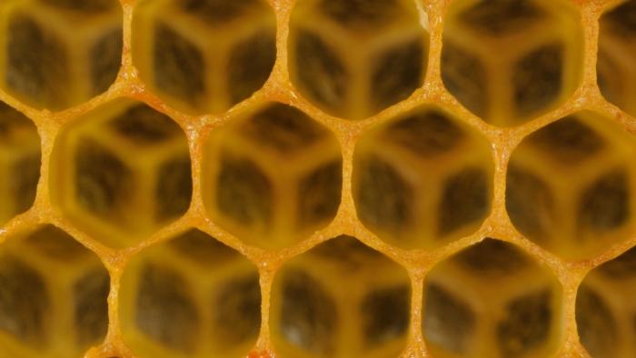
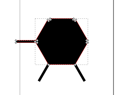
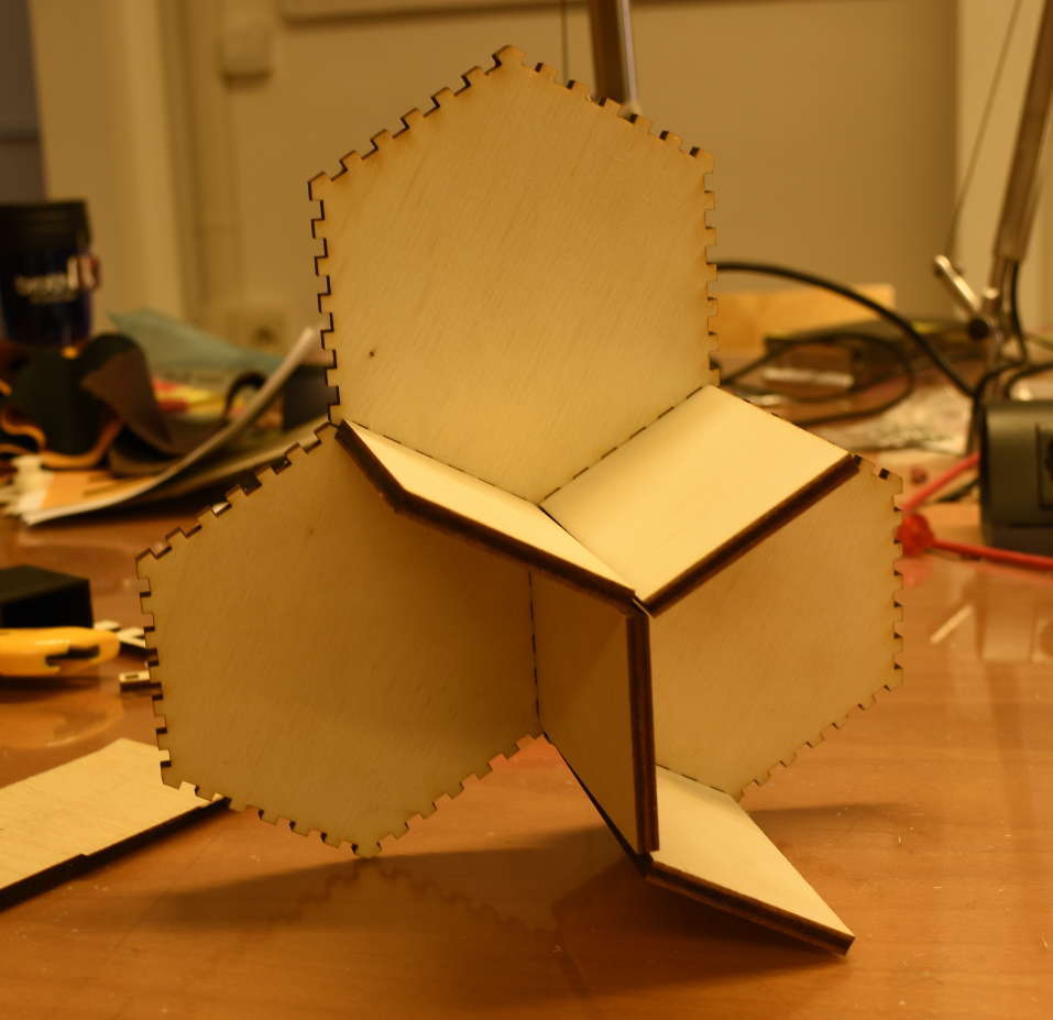
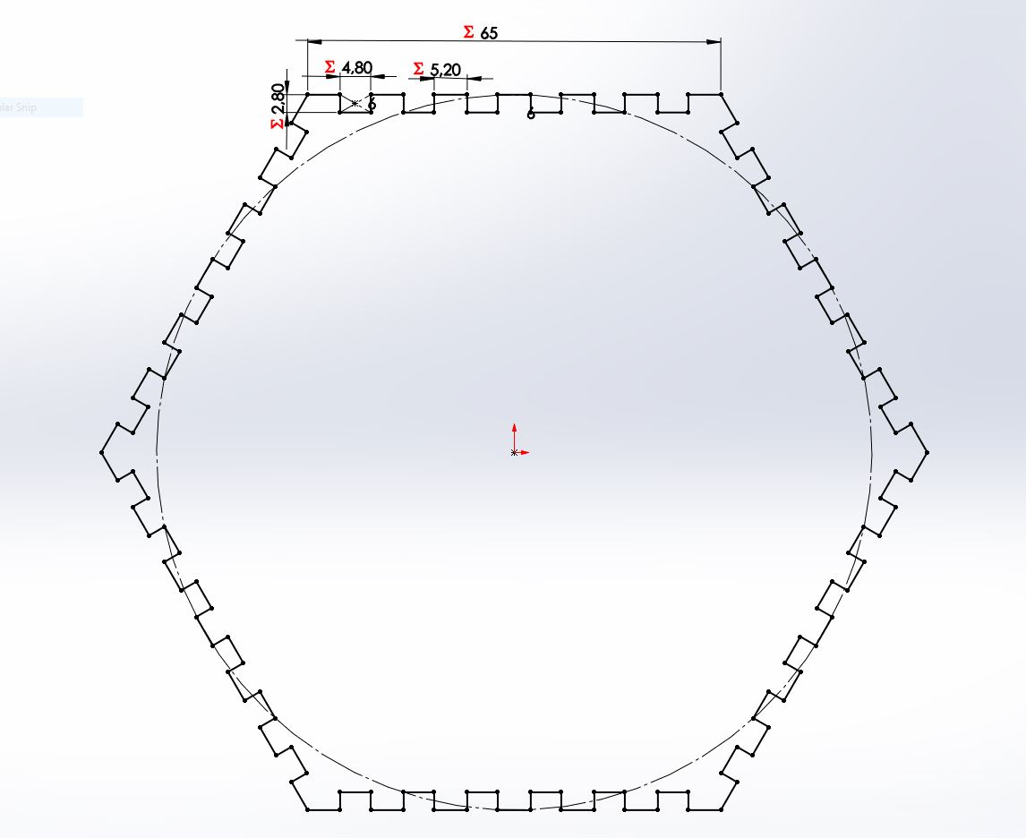
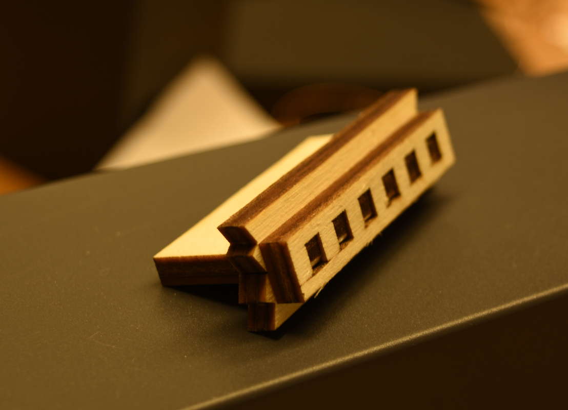
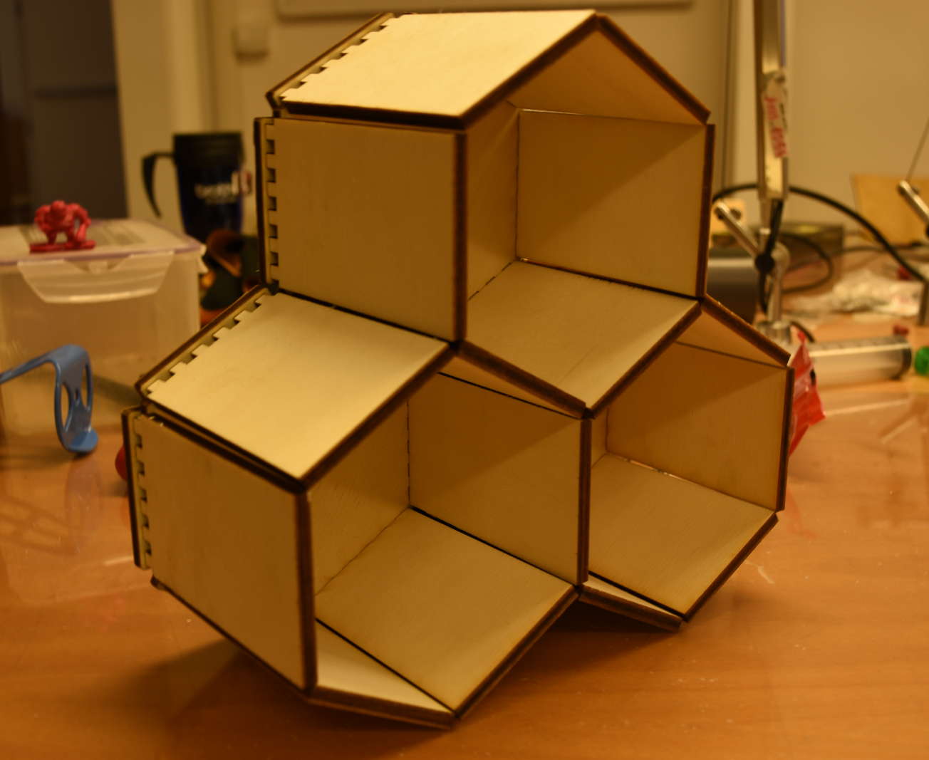
For this week’s assignment I decided to realise a series of combinable slots for storing things. The design is inspired by a honeycomb!
In my first design project, the rectangular boards which define the cells should stay fitted to each other, creating something like a through hole, just like in the natural world.
To make boards in this way I would have neded a diagonal cut through the Z axis, due to cells shape that is not squared but hexagonal.
It was not possible to achieve that because the machine we have in our lab, a Trotec Speedy 400 flexx, works only in X and Y axis.
So I changed the design including a hexagonal slab of wood in which fit boards leaving a small space between them.

To join more slots together I could use the same board for two slabs.
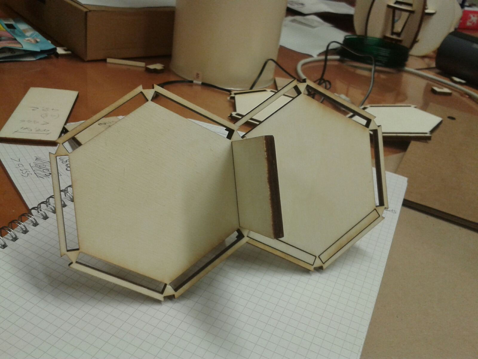
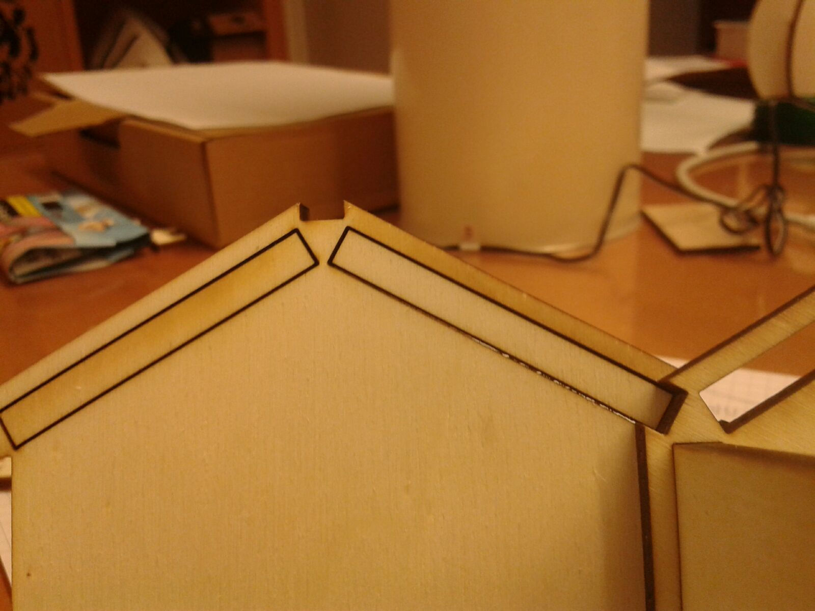
But in this way there was some of the hexagon's corner that partially crossed the near fissure. To solve this problem I created other cuts on the corners to let the boards pass through two slabs.
That’s it! Now my honeycomb is combinable in any number of pieces I want.
2D modeling process
To model my press-fit kit I used Inkscape. I started using this software last week and I decided to go on with it in order to train more my skills, I think it is a very useful tool.
On GitHub I found a smart tutorial to learn how to use Inkscape parametric.
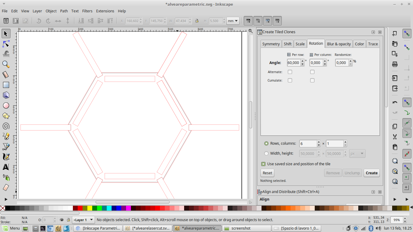
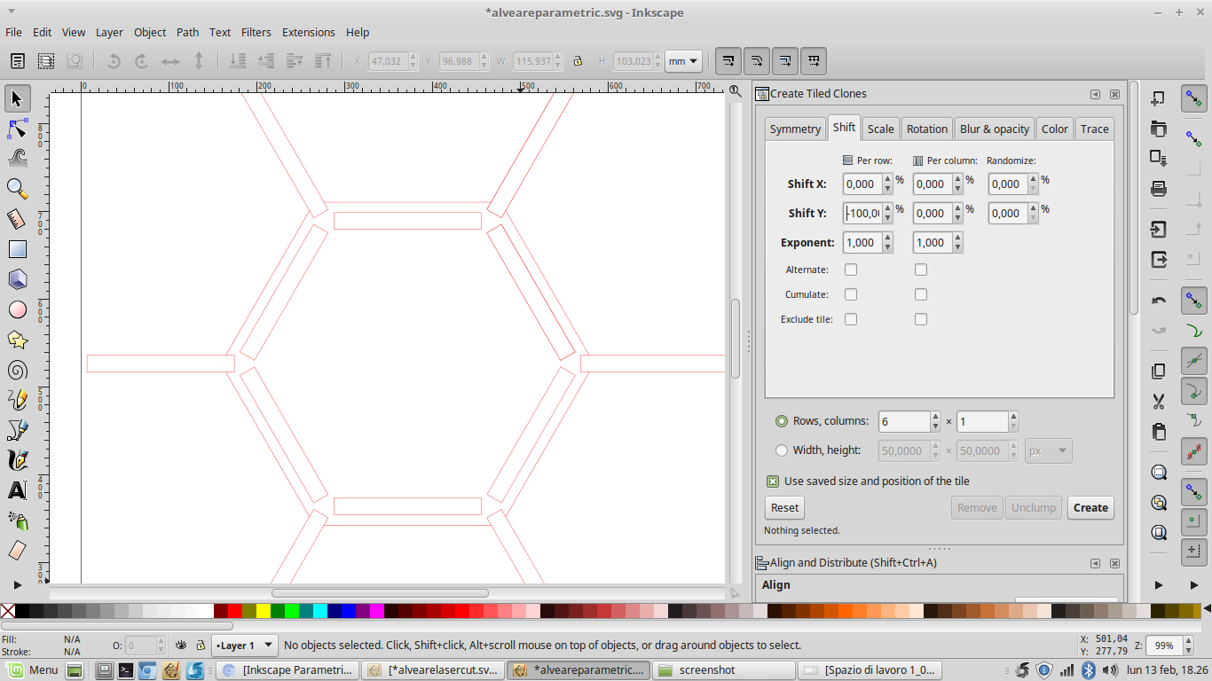
It works with XML editor, but in this moment I prefer to use the graphic interface. I found it a bit hard for my current level. So I tried to use clones, more precisely “tiled clones”.
This tool in Inkscape allows you to create multiple clones of an object to whom you can modify size, position, rotation, etc. just by modifying the original one.
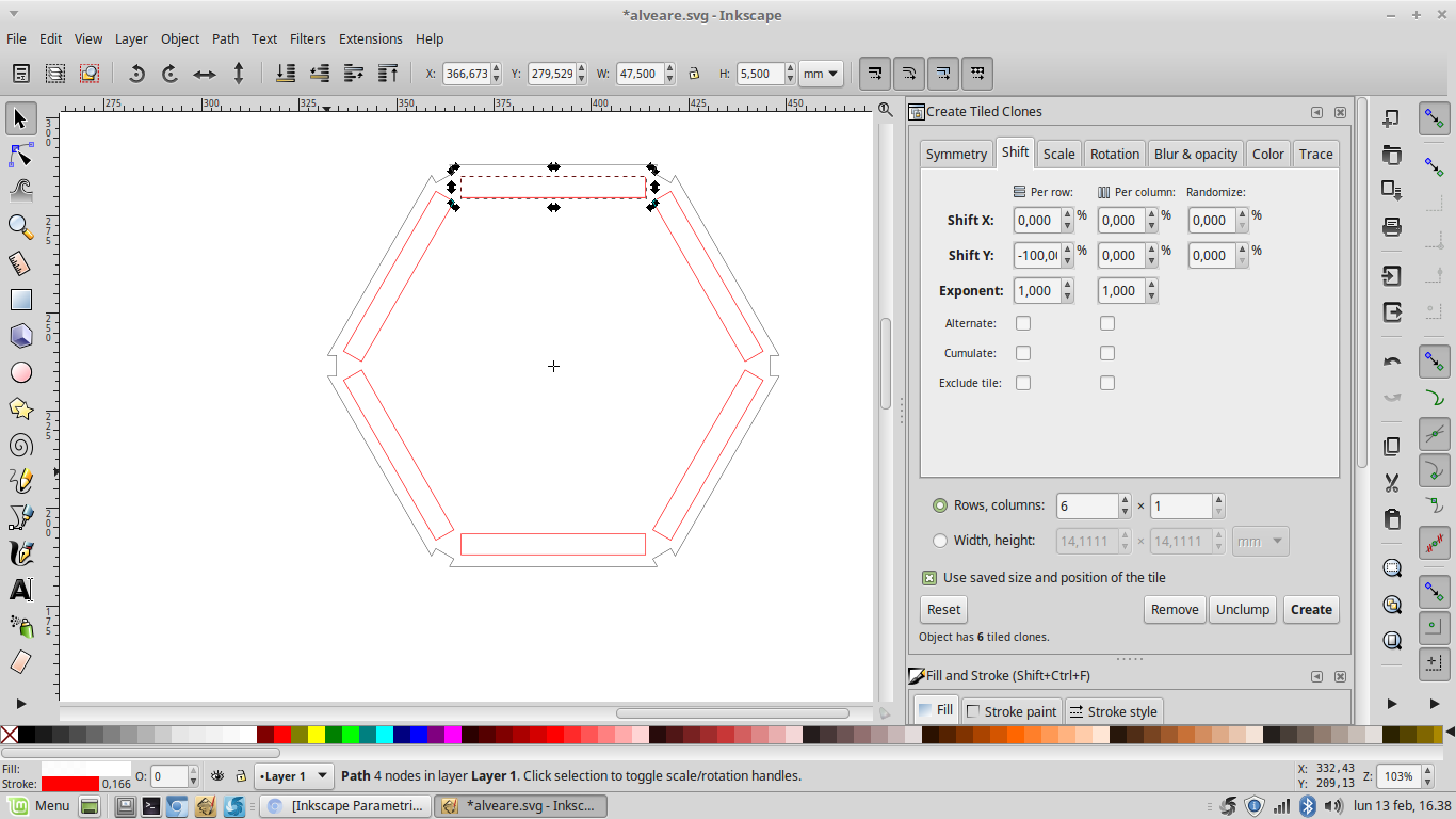
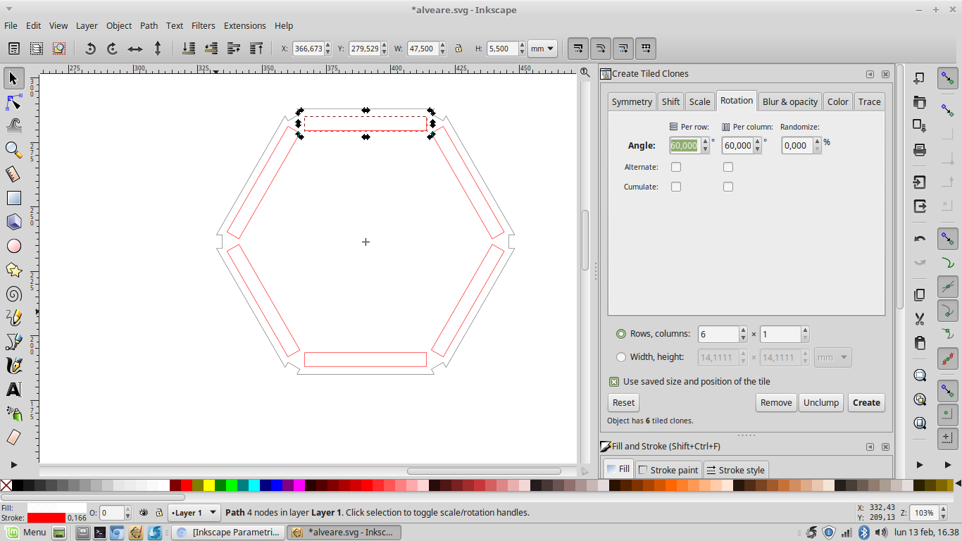
In this way I easily positioned all my fissures where I needed and I could also modify their width and height.
I used the same method to position other rectangles on the hexagon corners.
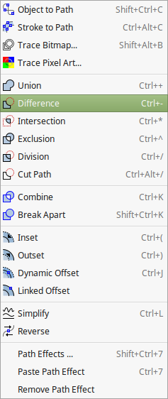
Moreover in order to create little squared cuts I converted all my objects path and then I made the "difference" between them.
So when I had to change my fissure size I only had to modify one object. This has been very useful when I had to adjust cuts according to the laser cutter kerf.
Laser cutting process
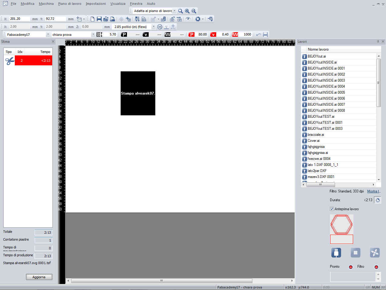
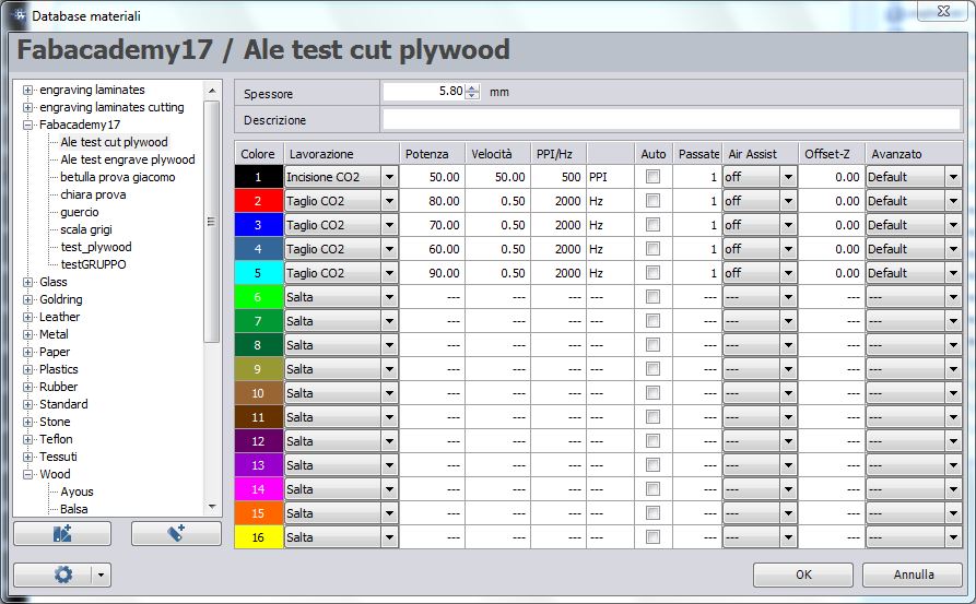
The software I used to manage the laser cutter job is JobControl
It has a very easily understood interface, that let you set cutting and engraving parameters, like power, speed, Hz (for cutting) or PPI (for engraving), number of passes, and also let you create material database in wich you can save those settings
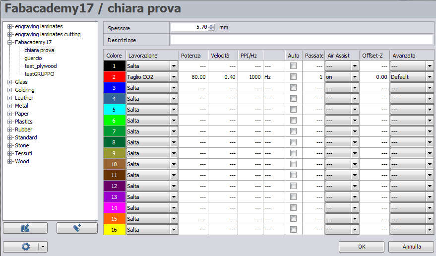
Once the 2D model is made you only have to print it selecting the Trotec as the printer
Here you have to specify the size of you project canvas (it's recommended to add some millimeter to the actual size)
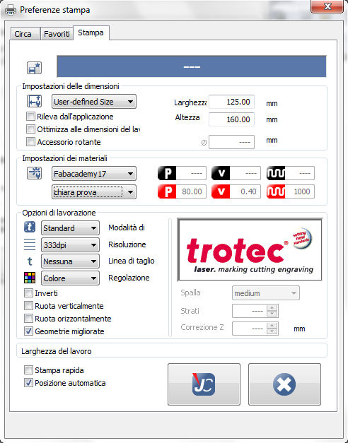
I built my model with a poplar plywood panel thick 5.7mm, and I set power at 80W and speed at 0.4%. Using this setting with that material I obtained a kerf of 0.14 mm.
I knew that this method is not properly what is meant to be parametric. Next days I want to try some other software for 2D parametric design.
You can see our group work to test kerf here
Update
During the following days I had the opportunity to make some additional test with the laser cutter
I made other tests concerning kerf and related cut settings, and I've found my personal settings for 5.8mm plywood at 80W and 0.5% speed giving a kerf of 0.05mm
I also wanted to study deeper the laser engraving, so I made some test setting different power and speed to get lighter and heavier engravings
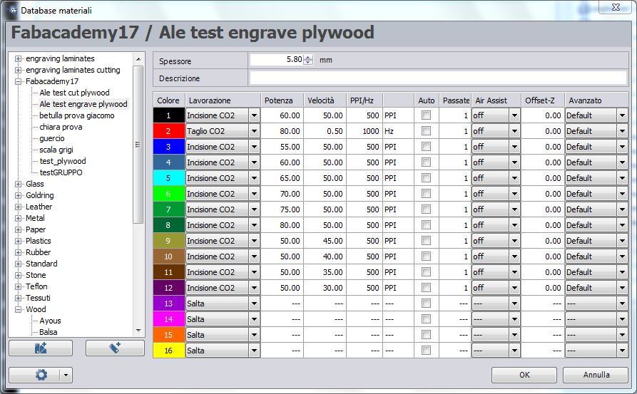
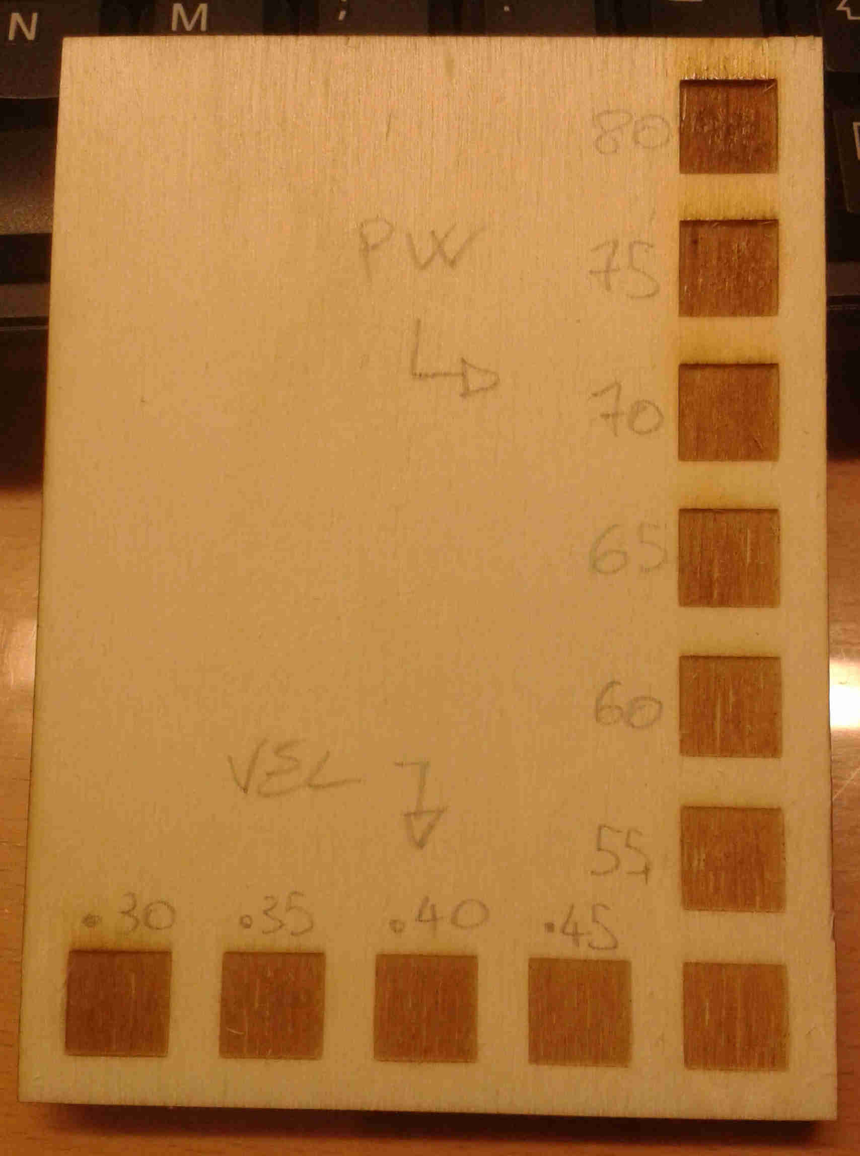
For this test I kept constant one of the variables and changed the other one step by step. The starting setting was 50W for the power and 0.5% for the speed
Leather
Then I tried to laser cut some other material. I started with a piece of dual layer leather thick 3mm
The settings I've found working well are: power at 90W; speed at 0.65%; 1000Hz; 2 passes
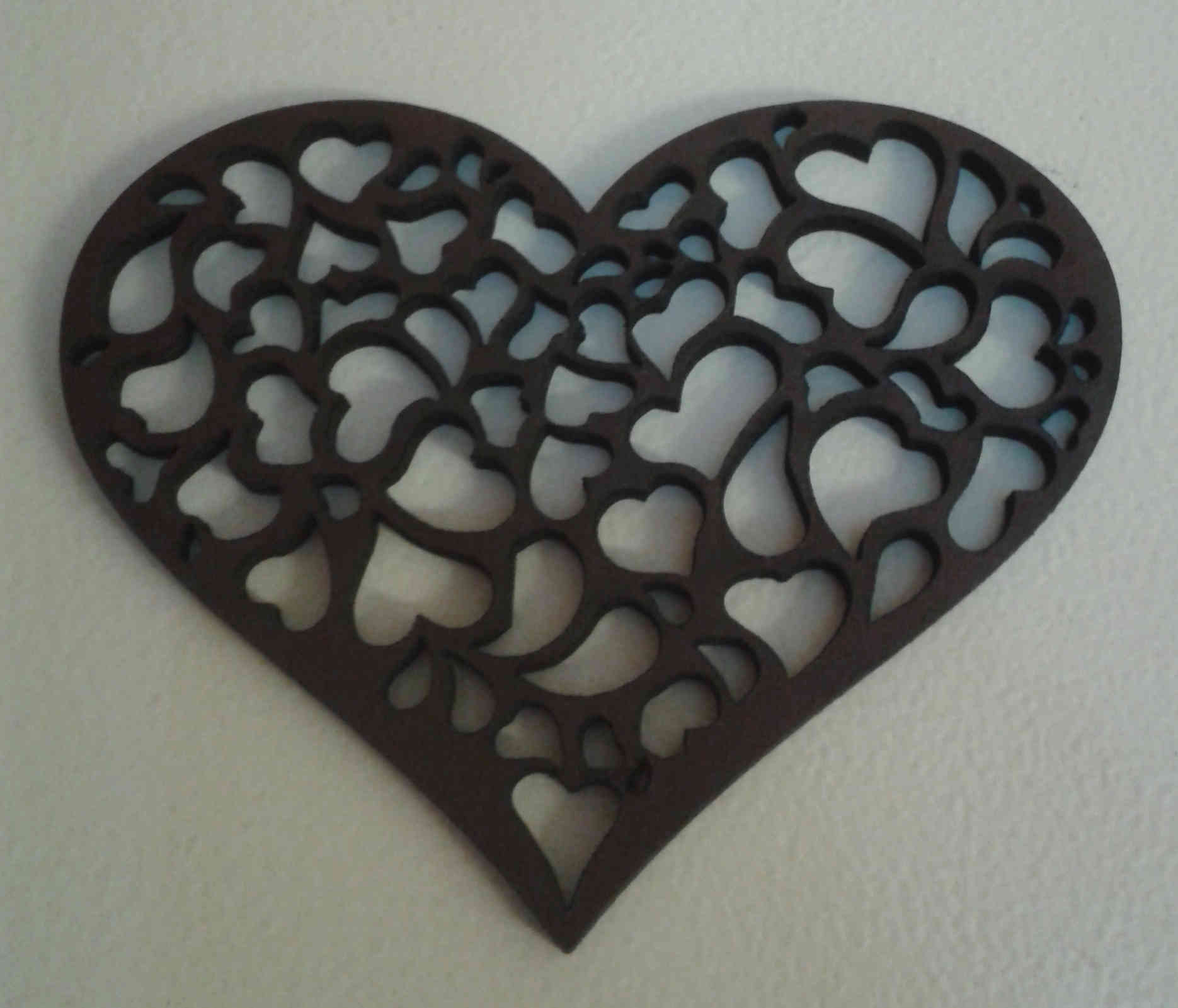
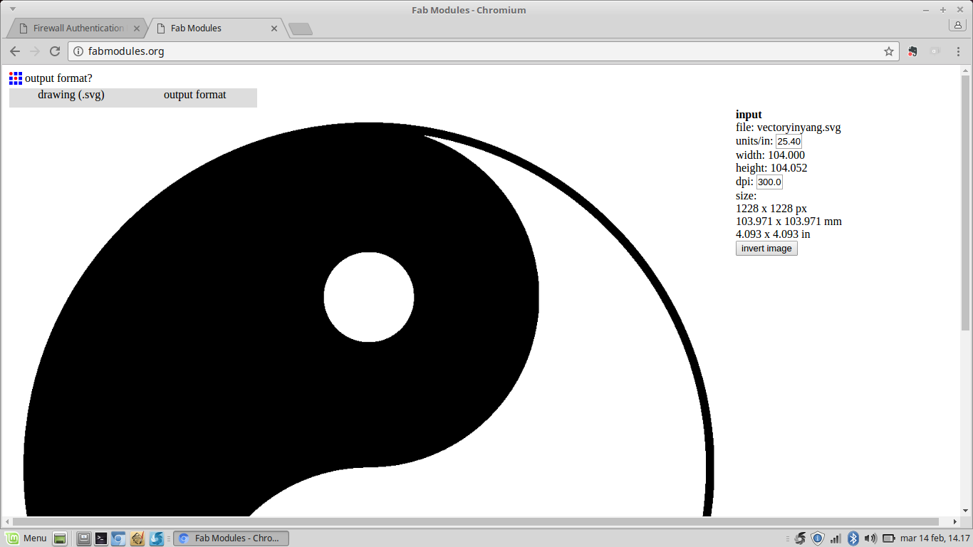
Once I've found those settings I couldn't help cutting something. So I downloaded the picture below (the black one) and I drew the outline. Of course I changed the color of the inner path to be cutted too (white fill and red stroke)
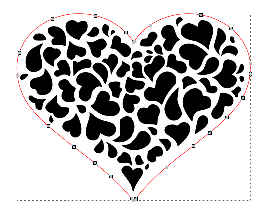
That's the outcome...
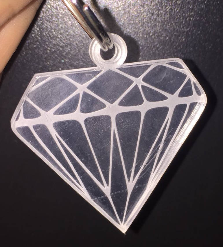
Plexiglass
I also cutted and engraved 3mm transparent plexiglass

For the cutting I set power at 100W and speed at 0.3% and 5000Hz. For the engrave 80W and 0.45%
Update 2
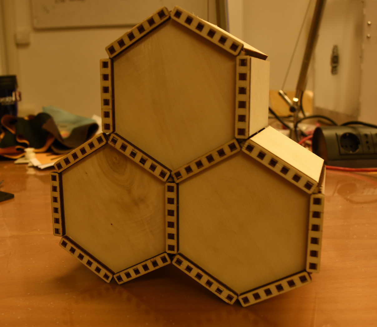
Parametric press-fit kit
Since my first parametric press-fit kit was not enough, I wanted to make another one
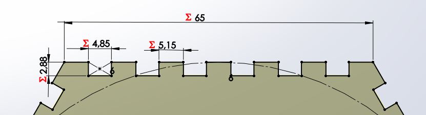
The main concept, the honeycomb, is the same of the previous time, but I changed the design to use finger joints
This model is made by three components: hexagonal central frame, lateral boards and back joint holder, which give structure and keep all pieces together
Design process
This time I modeled it in Solidworks, since this software allow parametric design using equations
So first I've searched some tutorial on the internet about it and I've found this short video on youtube and the related page on Solidworks web site
Then I started to design
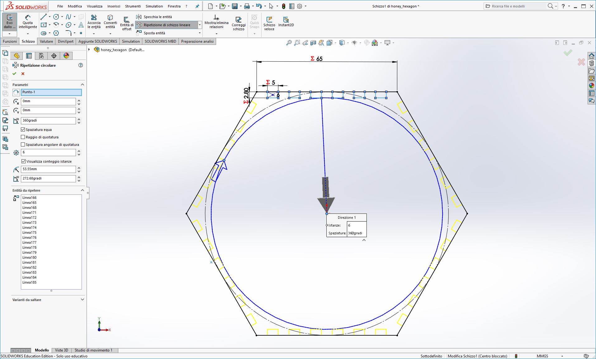
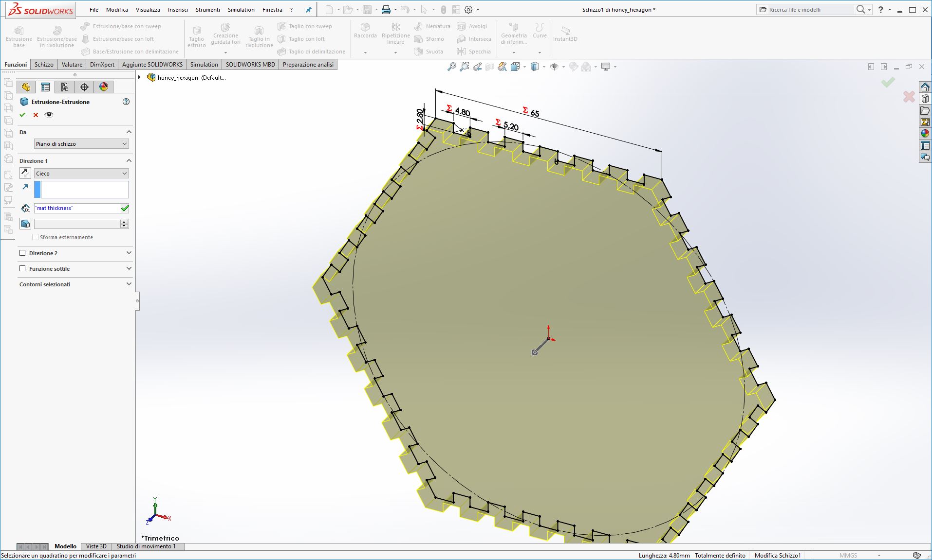
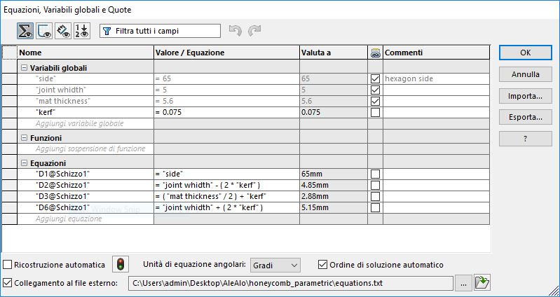
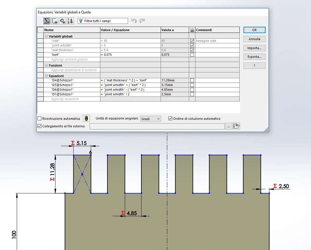
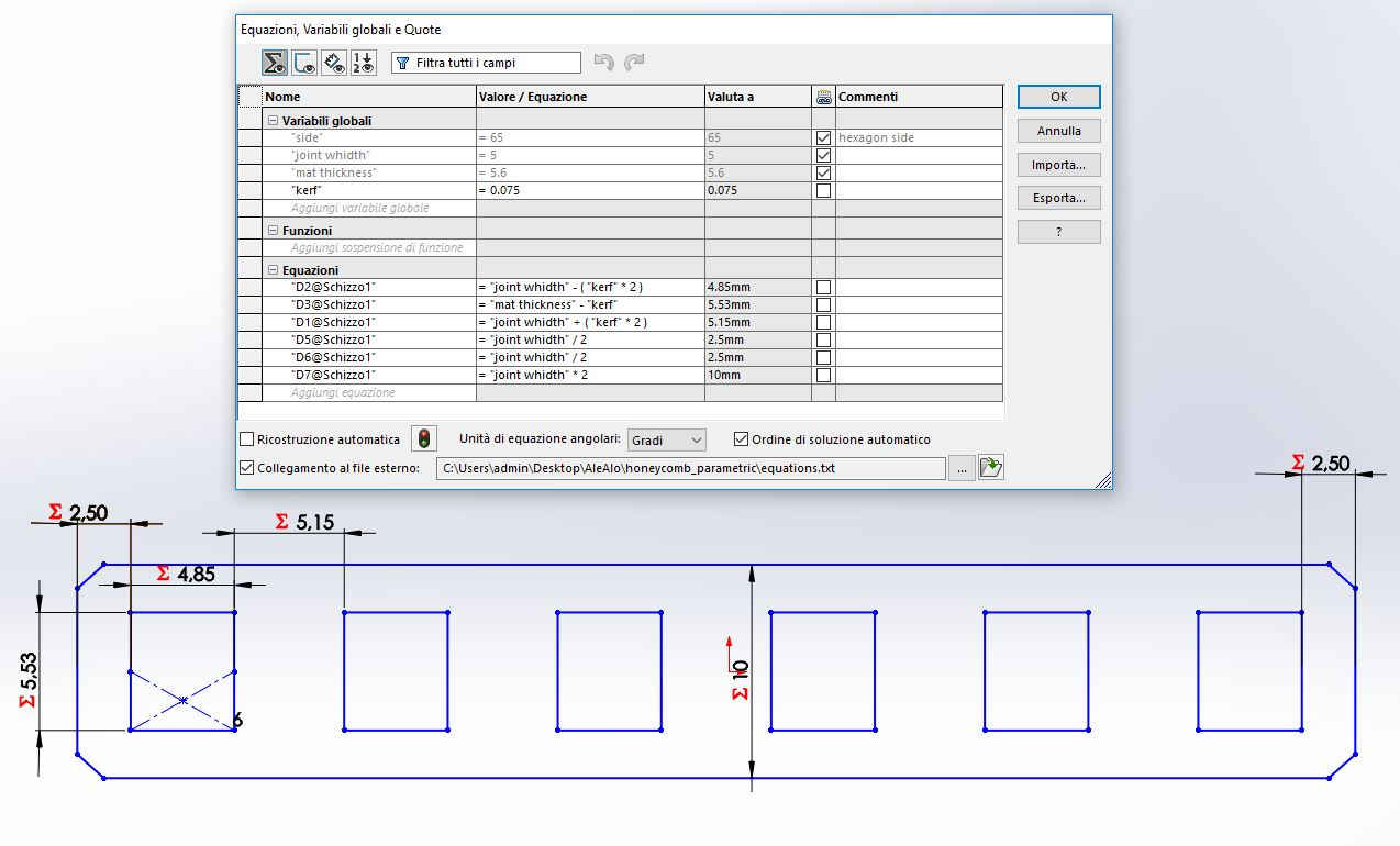
After I've defined variables and equations in the first part of the model (the hexagon) I could export them in a .txt file and import the file in the other parts of the model. In this way you haven't to write them again in all your files
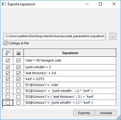
As you can see I only exported the variables values, which were common in all the parts, but not the equations. In this way I could edit relations (equations) between variables according to the new design part
Laser cutting test
Once the design was made I moved to the laser cutter. But since I had to use a new board (thick 5.6mm) I had to calculate again the kerf
So I made some test...
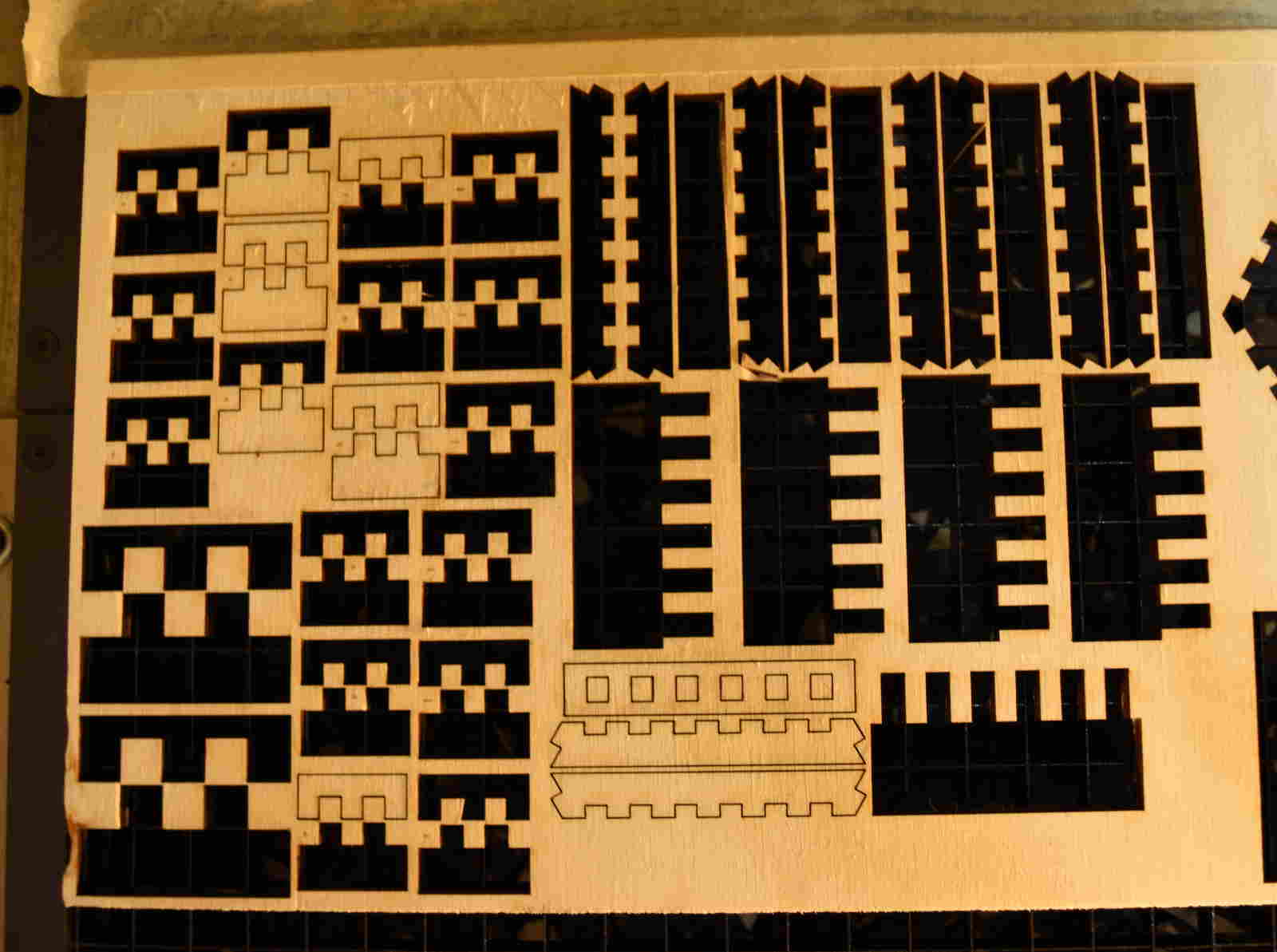
And I've found a kerf of 0.075mm setting power at 80W and speed at 0.6%
Assembling the model
Vinyl Cutting
For this part of the week's assignment I cutted some stickers using different kind of vinyl we have in our lab
I made the model with Inkscape, and prepared the file using both Fab Modules and CutStudio, the Roland’s software.
Fab Modules
Fab Modules provide a set of software tools to run any Fab Lab machine.
This time I used them to create the file .camm which was readable by the Roland GS-24
To practice managing those new things I downloaded an image from the internet, got the .svg with Inkscape and cutted a sticker of it
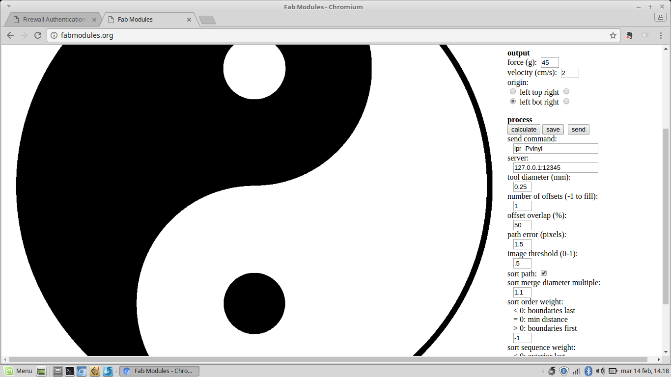
I set the image size and the machine parameters, force at 45g and speed at 2cm/s
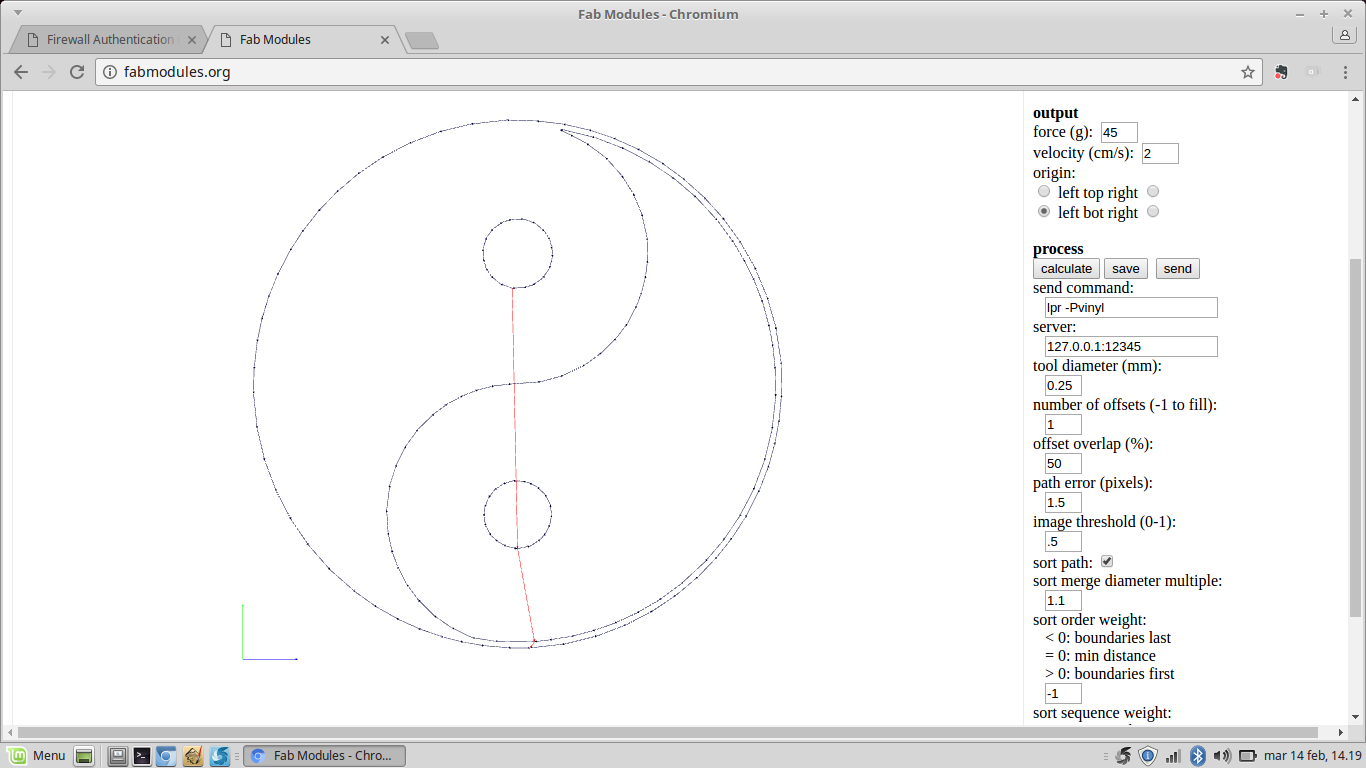
Then I've calculated the file and the software showed the path of the image (in blue) and the path the blade would be going to follow (in red).
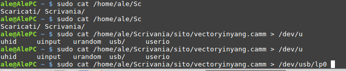
Once I saved the file I was ready to send it to the machine by connecting it to my computer via USB. I only had to find the path typing a "dmesg" command in the terminal.

So I sent my file .camm to the cutter.
Now I tried to modify a bit the image to personalize it
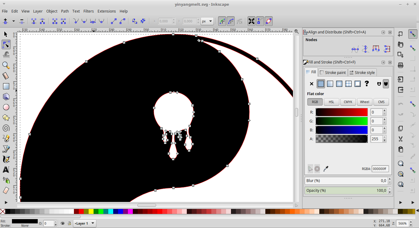

Since our cutter is not able to print I attached a small piece of red vinyl on the back side of the sticker
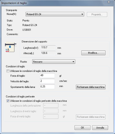
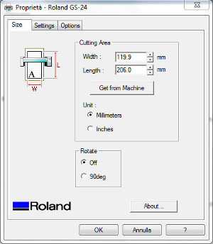
Cut Studio
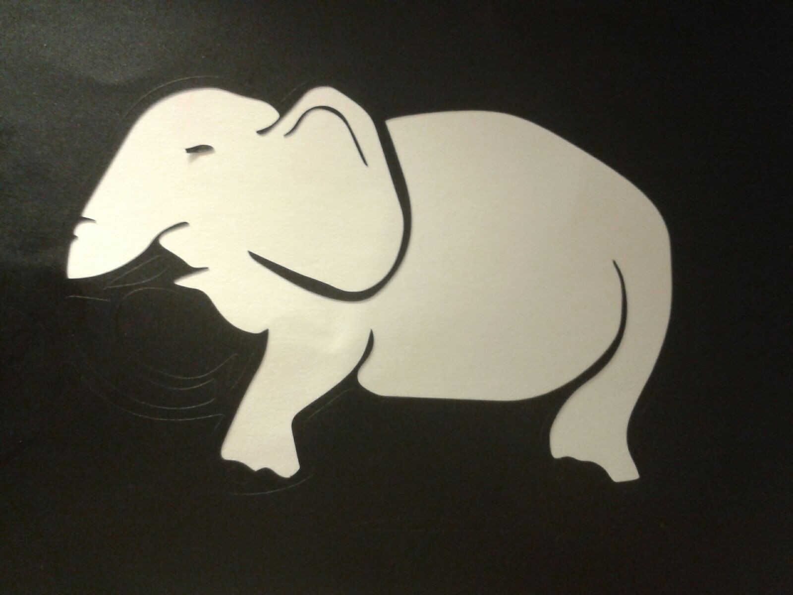
I also cutted another sticker using CutStudio.
I imported a png at 1000dpi resolution and I scaled it according to the cutting plane size
You can do this in two ways: putting a piece of vinyl in the Roland cutter and selecting “piece” using the machine's keypad, and it automatically calculate the surface’s size, alternatively from CutStudio you can "get from machine".
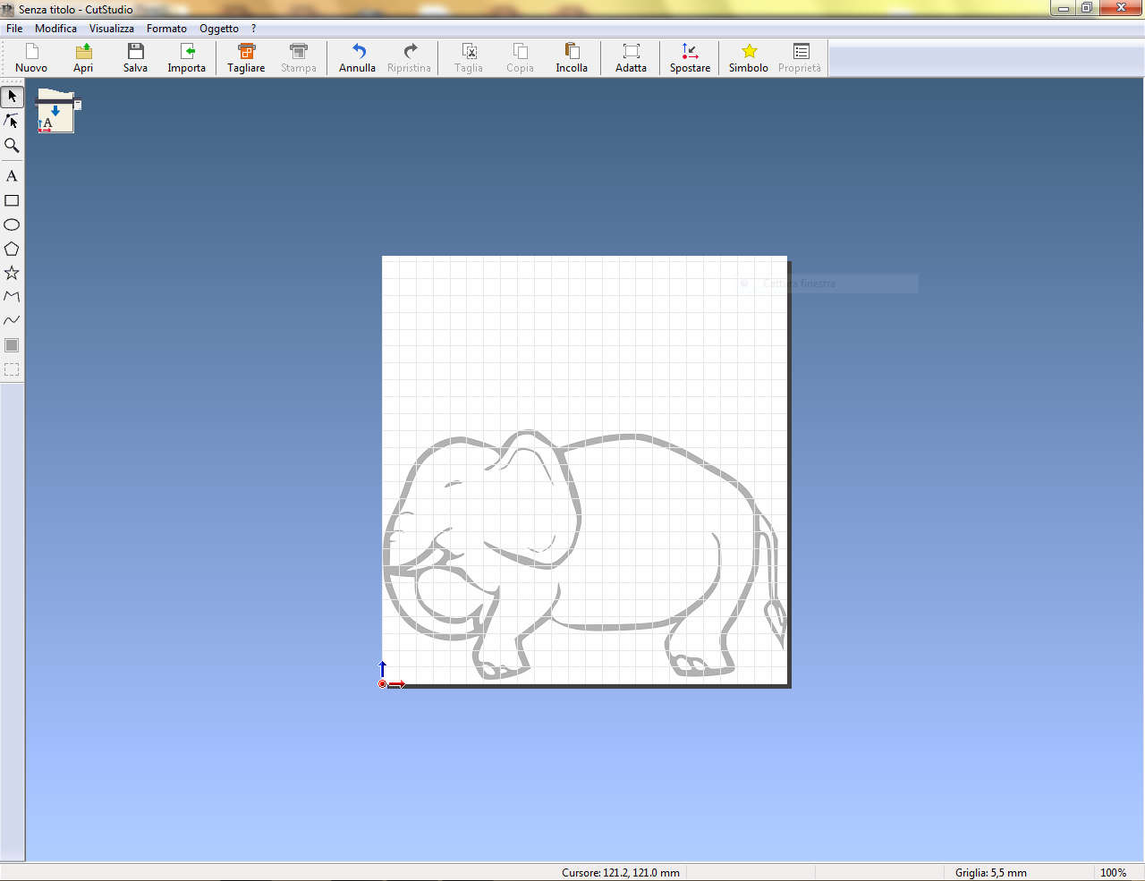
And this is the cutted sticker

To download original files click here