
WEEK 7 – COMPUTER-CONTROLLED MACHINING
Weekly assignment
This week's assignment was to make something big by designing and milling it with a CNC machine.
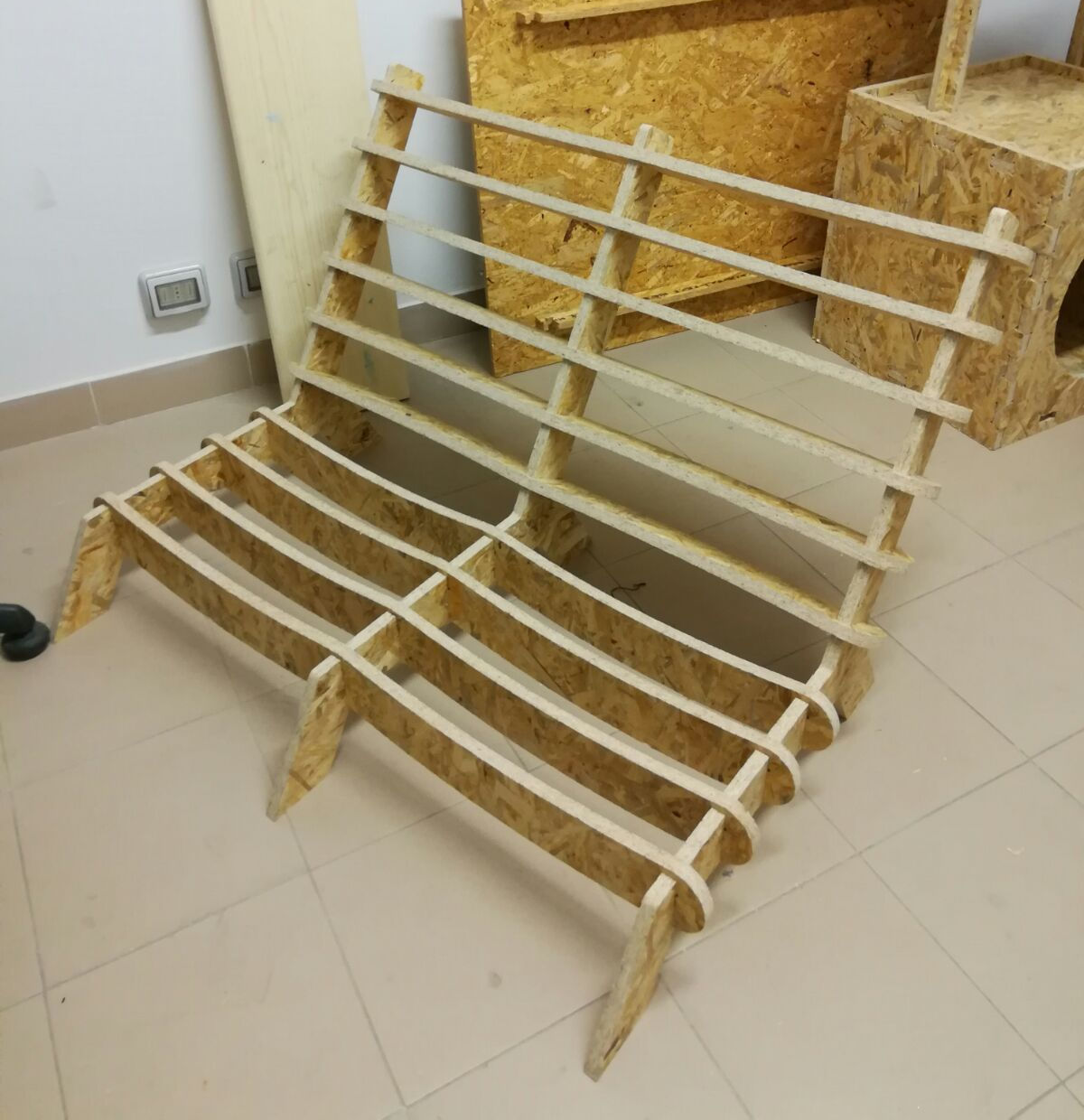
My project is a press fit two-seated deckchair.
Design process
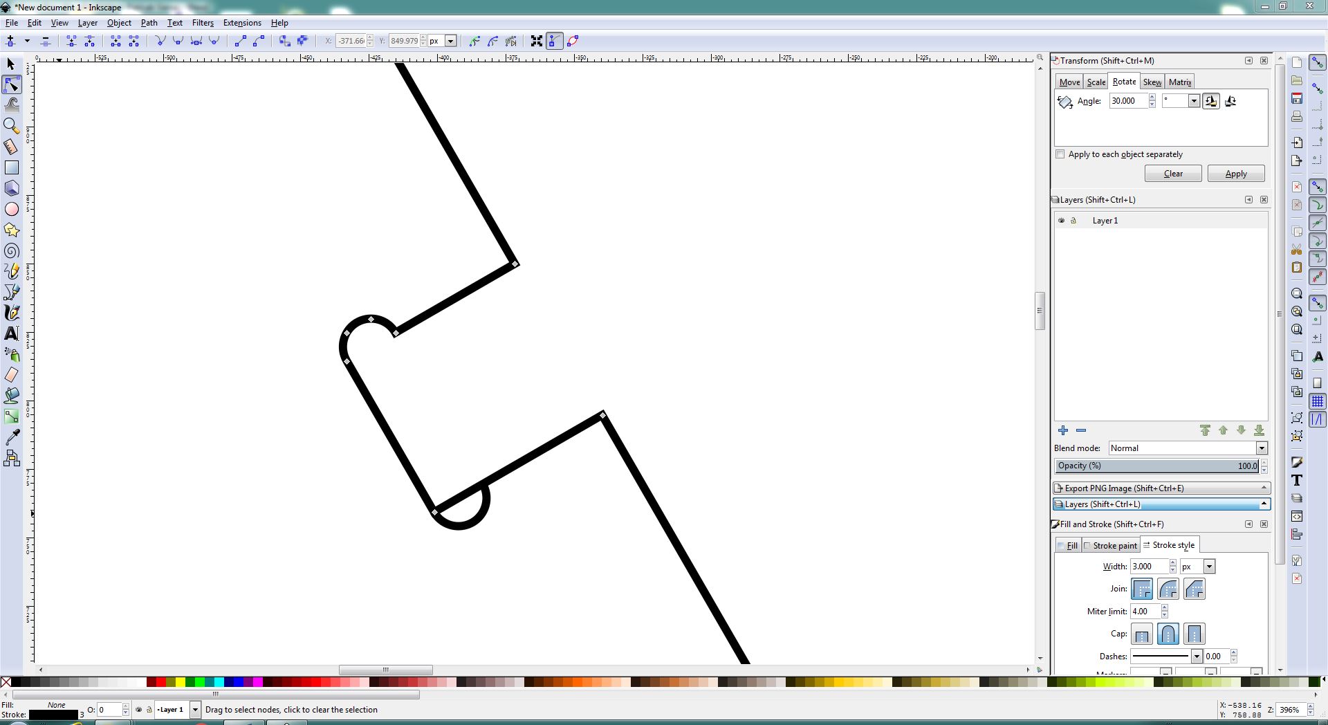
To realize the model I started from the 3D design. We have a trhee-axis milling machine that can only do two dimensional cuts, so I didn't need necessary a 3D model, I could use even 2D software like Inkscape or Illustrator.
But I first wanted to have a preview of the assembled object, then I decided to start from Solidworks.
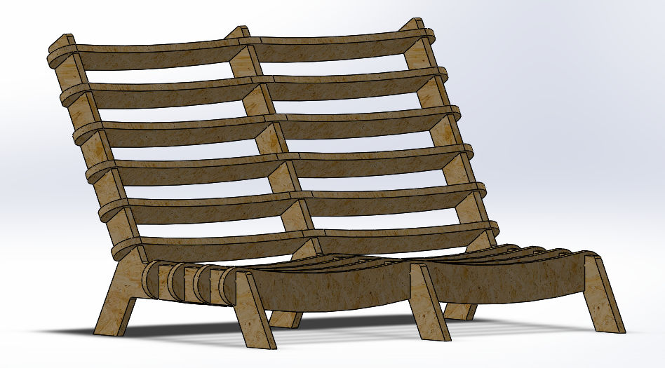
My model is composed by two different shapes each one is repeated more times to create the final model.
To make it I modeled two part file (frame and bridges) in Solidworks and after I made the assembly of those parts (weblinks refer to 3D files).
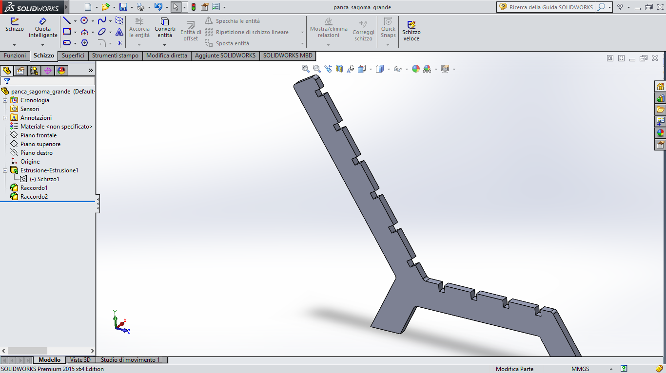
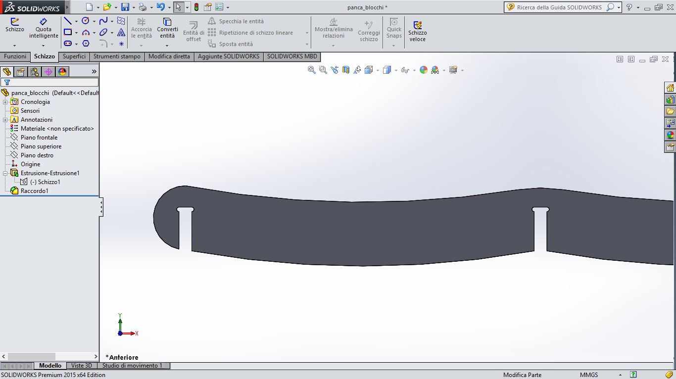
I started by drawing the frames, considering size and bending angle of the seatback, the chair seat and legs.
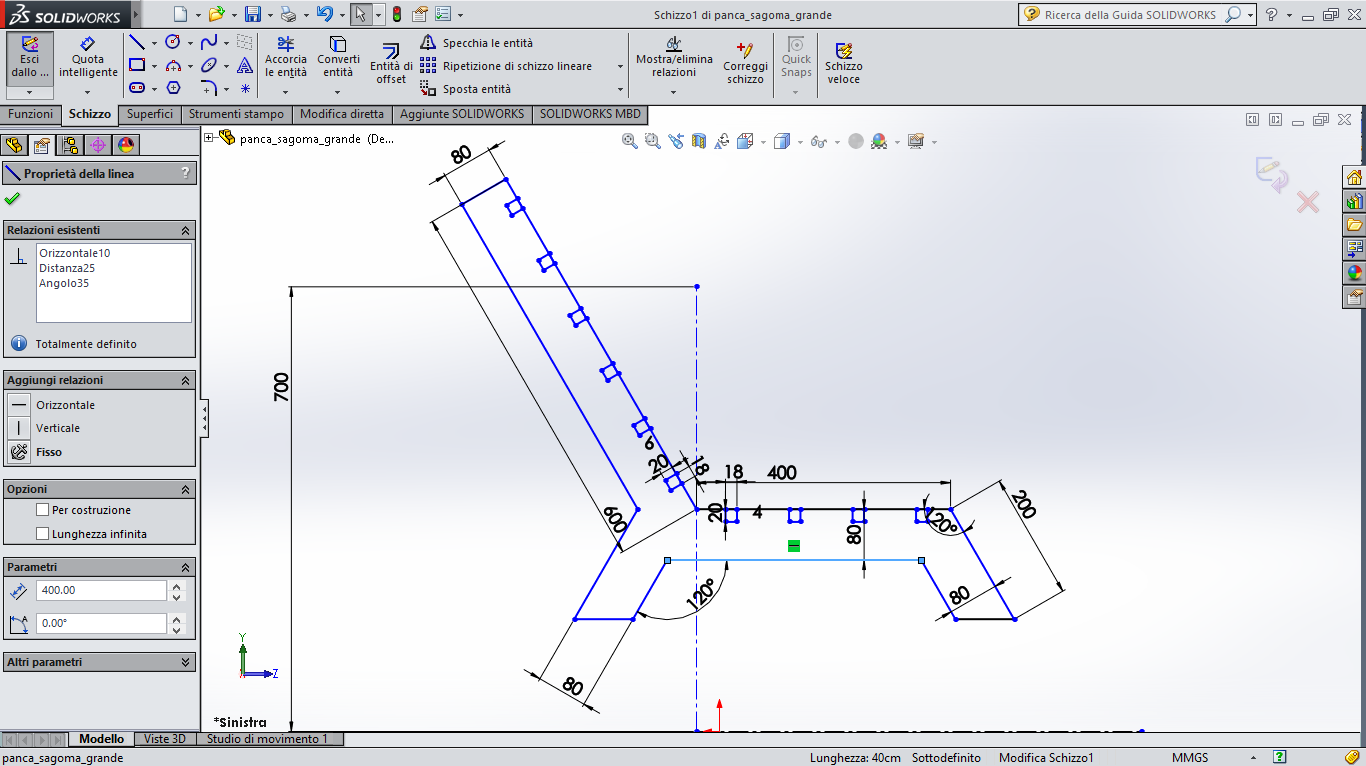
Then I extruded the shape (the amount is the board thickness) and added chamfers.
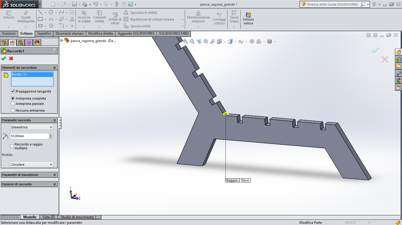
In this file I added all the joint fissures in a second time in order to give more stability to the chair, but I forgot to add t-bones.
This gave me additional work later, because I had to add t-bones manually, while I was ready to mill...
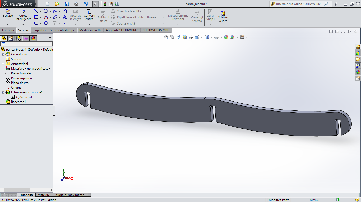
So I created another part file and drawn the bridge shape.
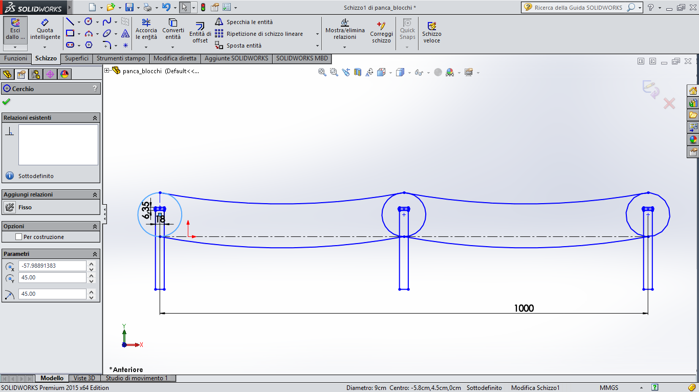
This time I didn't forget to insert t-bones...
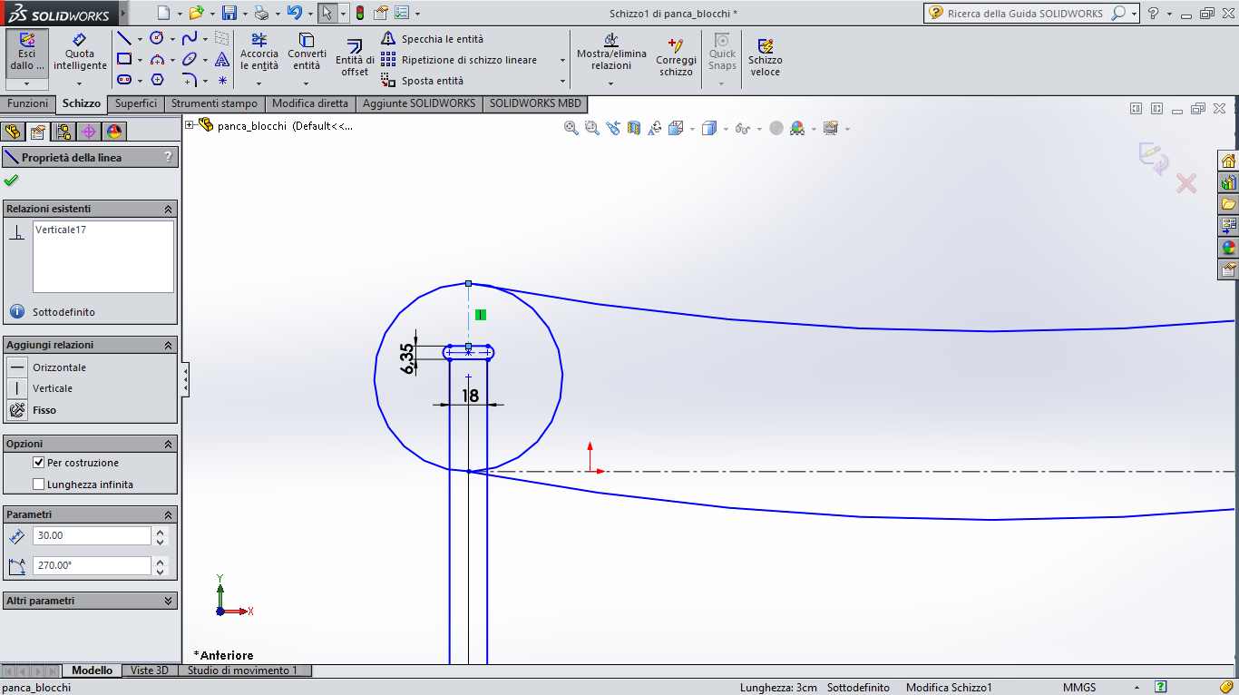
I knew I was going to use a 1/4 inch tip, so I setted the t-bones at the same diameter of the end mill (6,35mm).
T-bones are foundamental to have a squared cut, because the tip has a rounded shape and the cut would be rounded as well even if the path had a 90 degrees edge.
To export a DXF file I could use with the cnc router I used an option in Solidworks that let to export path of single faces of a 3D model.
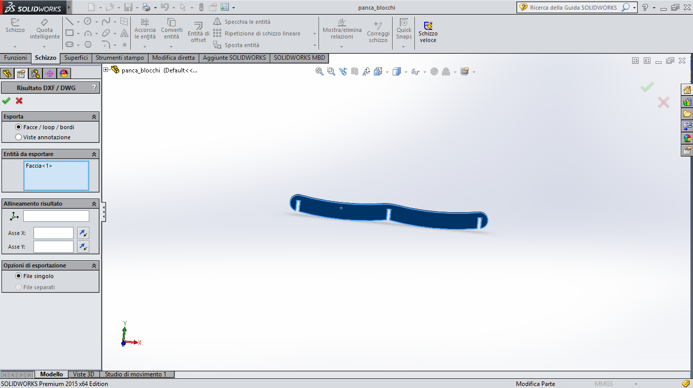
Deck Chair by allarollonz on Sketchfab
Milling process
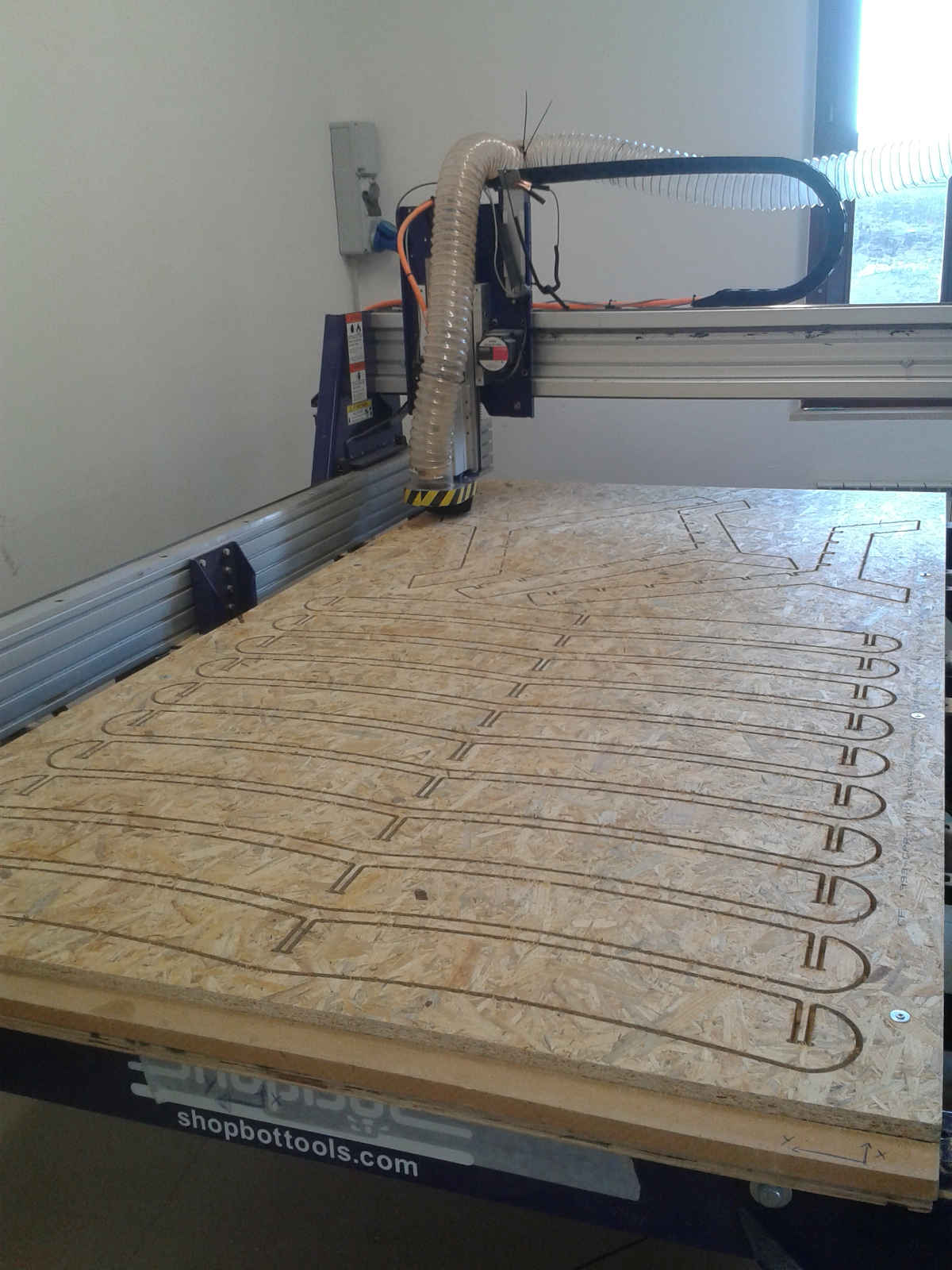
Now I could move to the machine...
In our Lab we have a ShopBot PRS alpha 96 wich has a bed of 240X120cm.
To make my model I used a particle board.
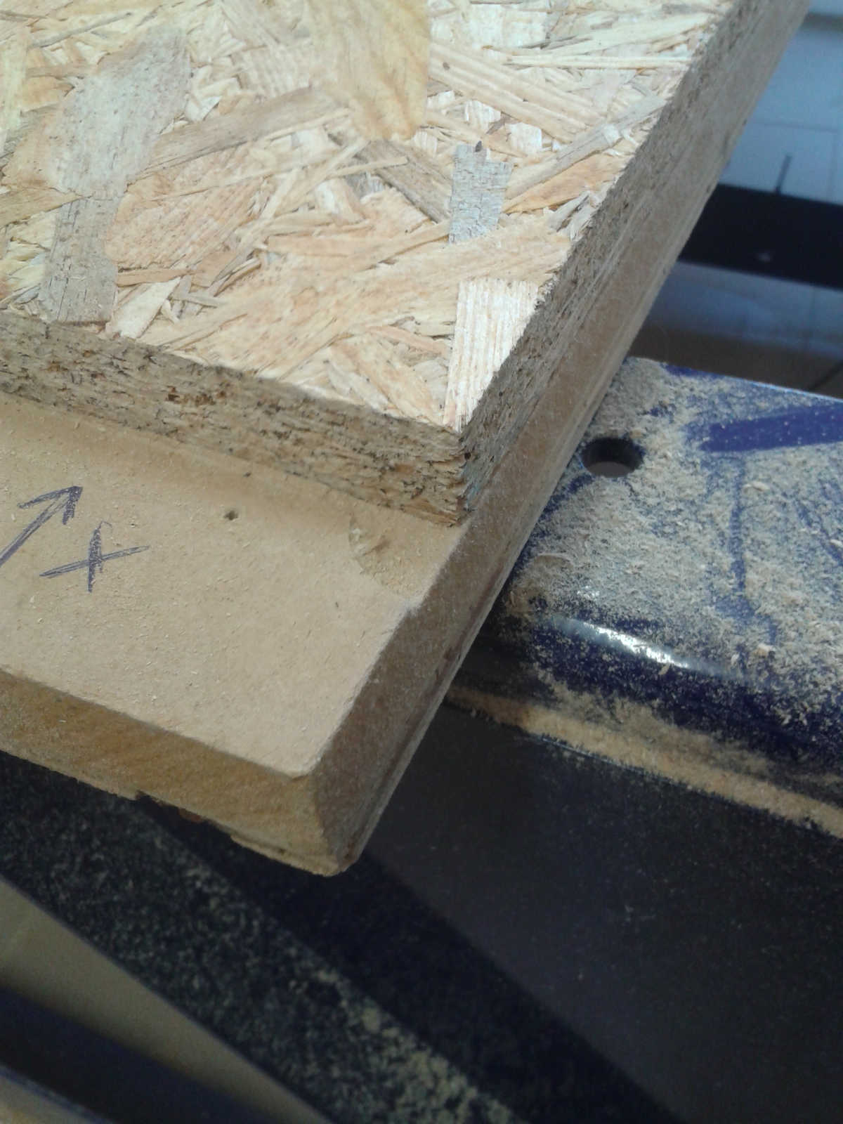
So once aligned the board to the machine bed I set the router position, first X and Y axis.
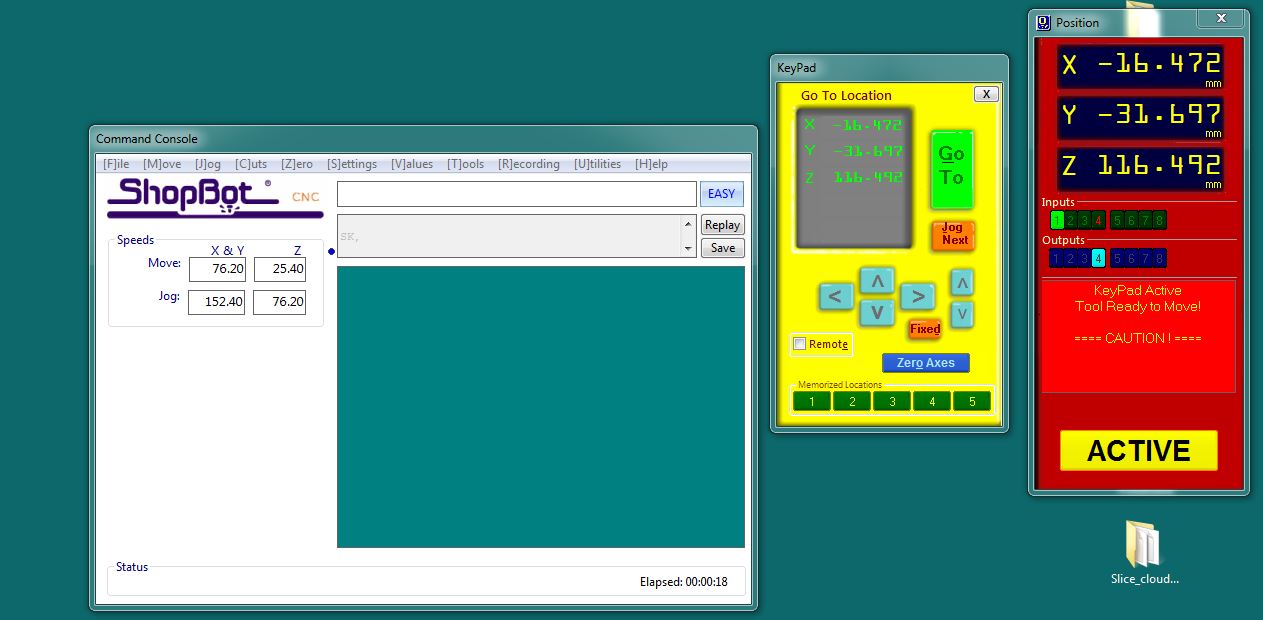
From the ShopBot command console I defined the origin point by clicking on "zero" menu and selecting "zero 2 axis"
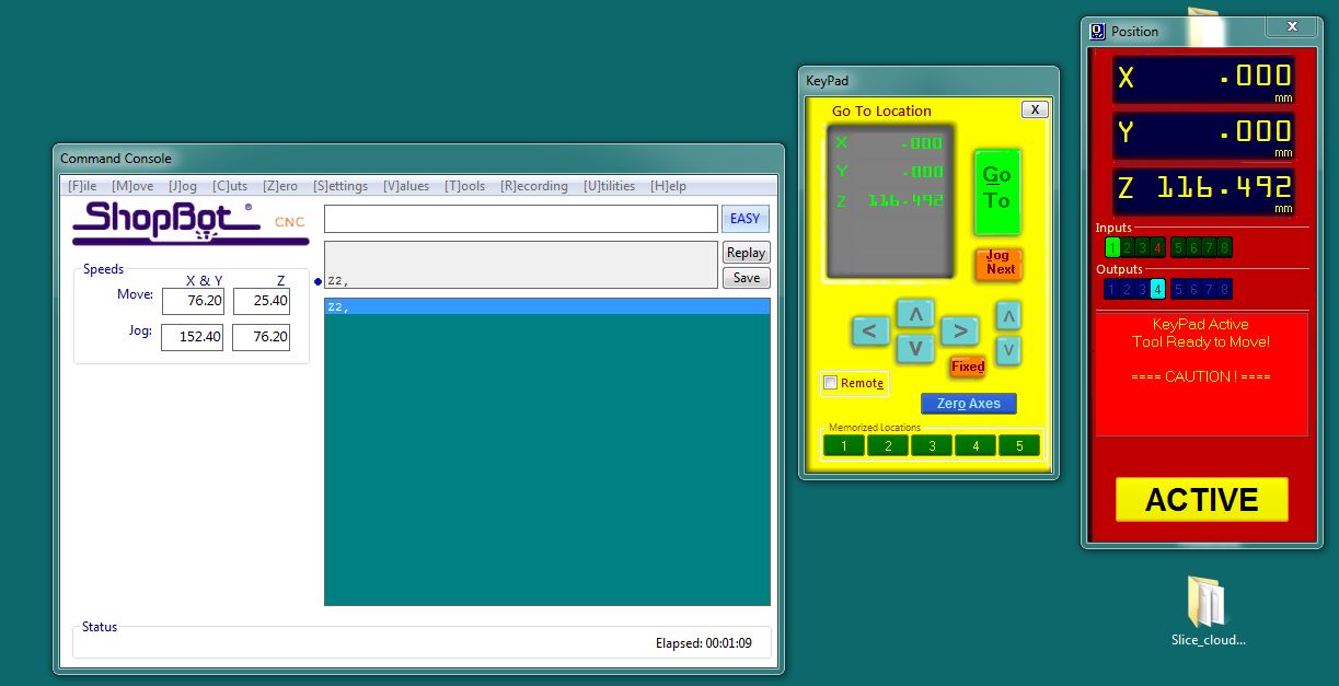
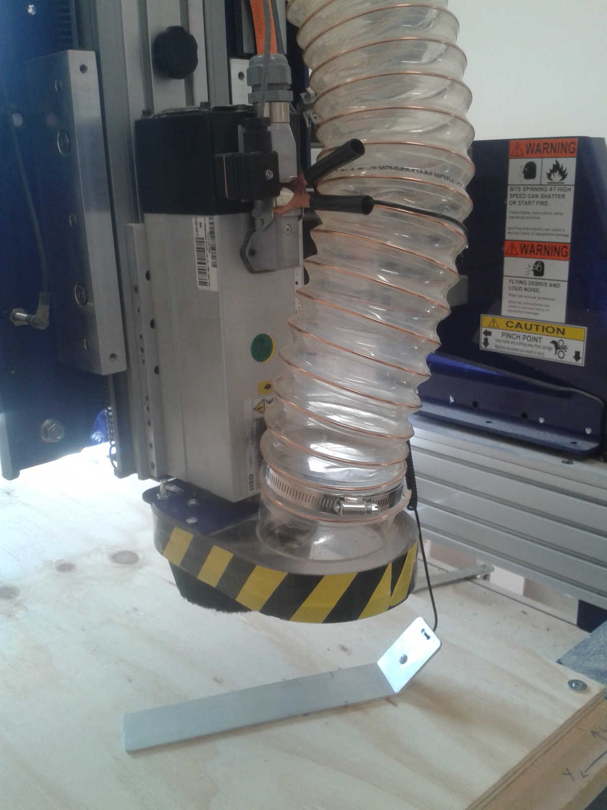
To set the Z axis the procedure is a bit different, because the machine does it by itself touching a metal plate that needs only to be connected to the machine through the clip you can see in the picture below.
Now from the "cuts" menu I selected "C2-Zero z axis/Zero plate" to start the procedure.
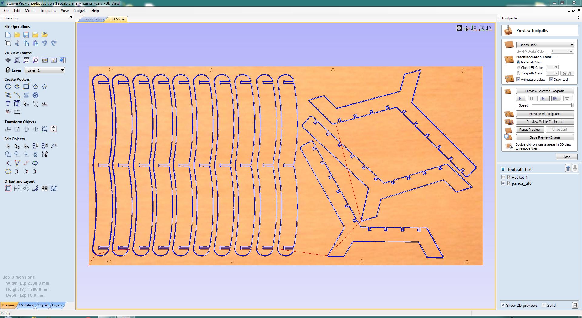
To set the cutting parameters I used VCarvePro ShopBot Edition.
I first create a path for some pocket in which after I inserted screw to anchor the board to the machine.
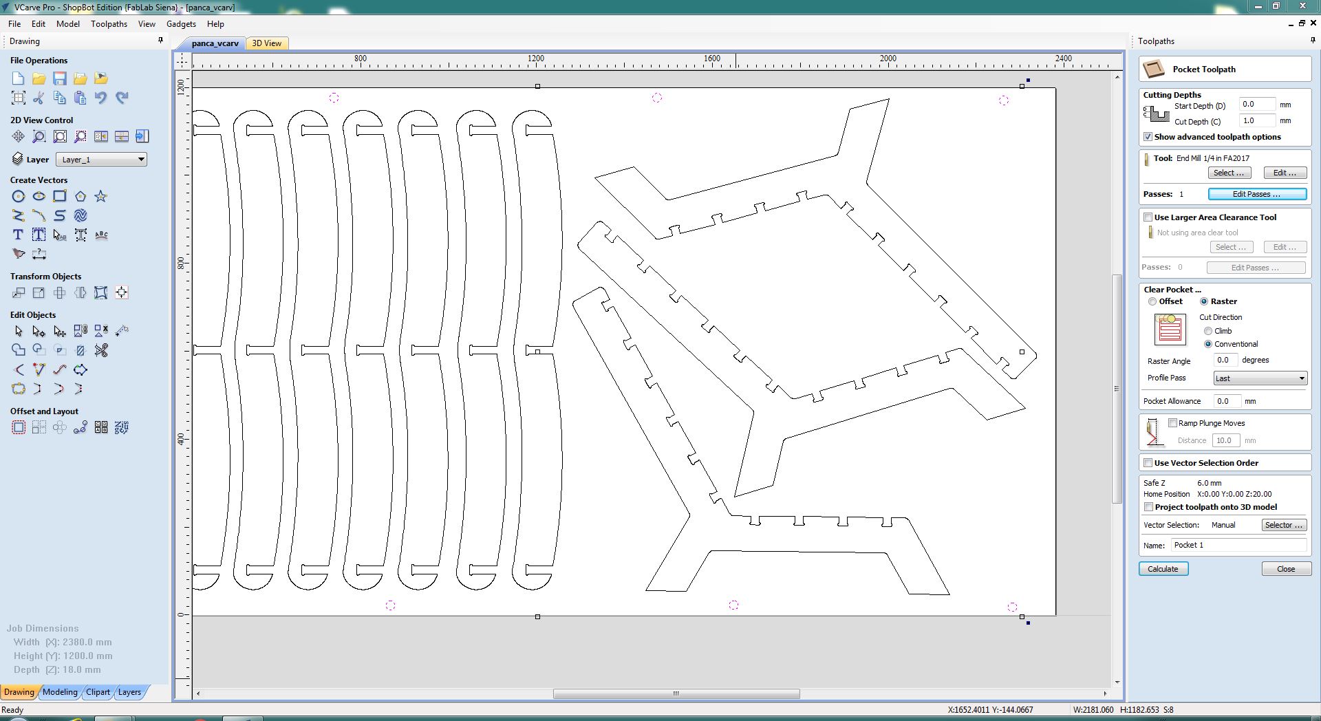
In the picture the cut depth is set at 1mm, but I changed this parameter to 2mm to see the sign better.
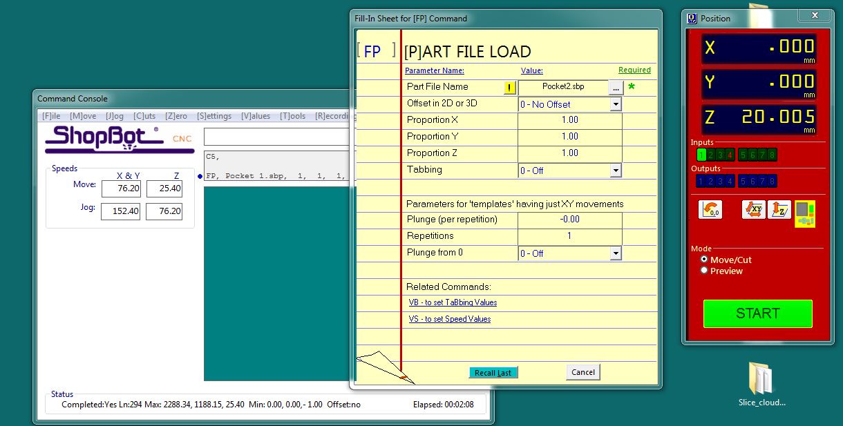
I did this to be sure that my cutting paths didn't run above the screw, it would be very dangerous!
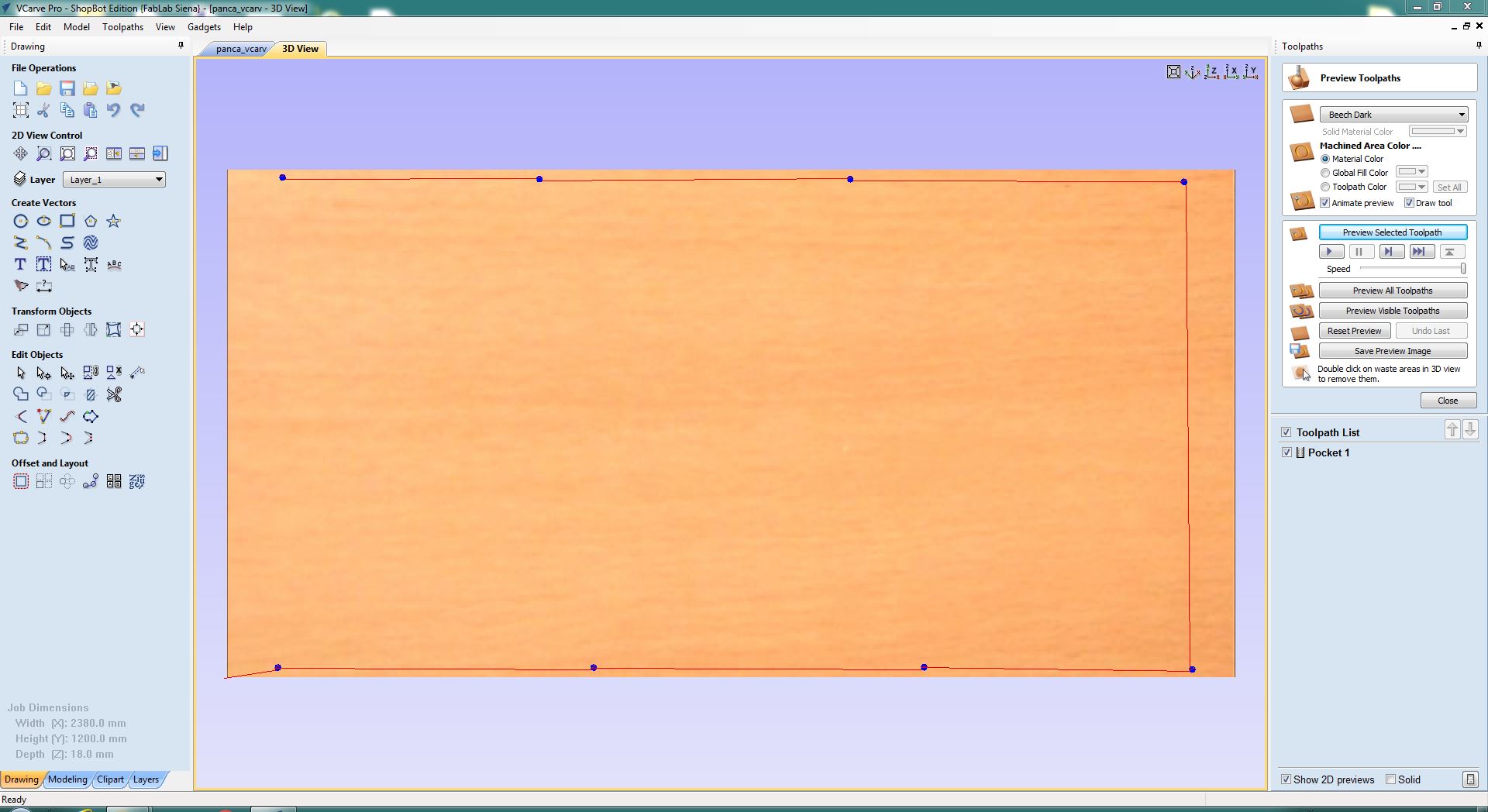
Now I imported my file in VCarve and placed shapes on the cutting area.
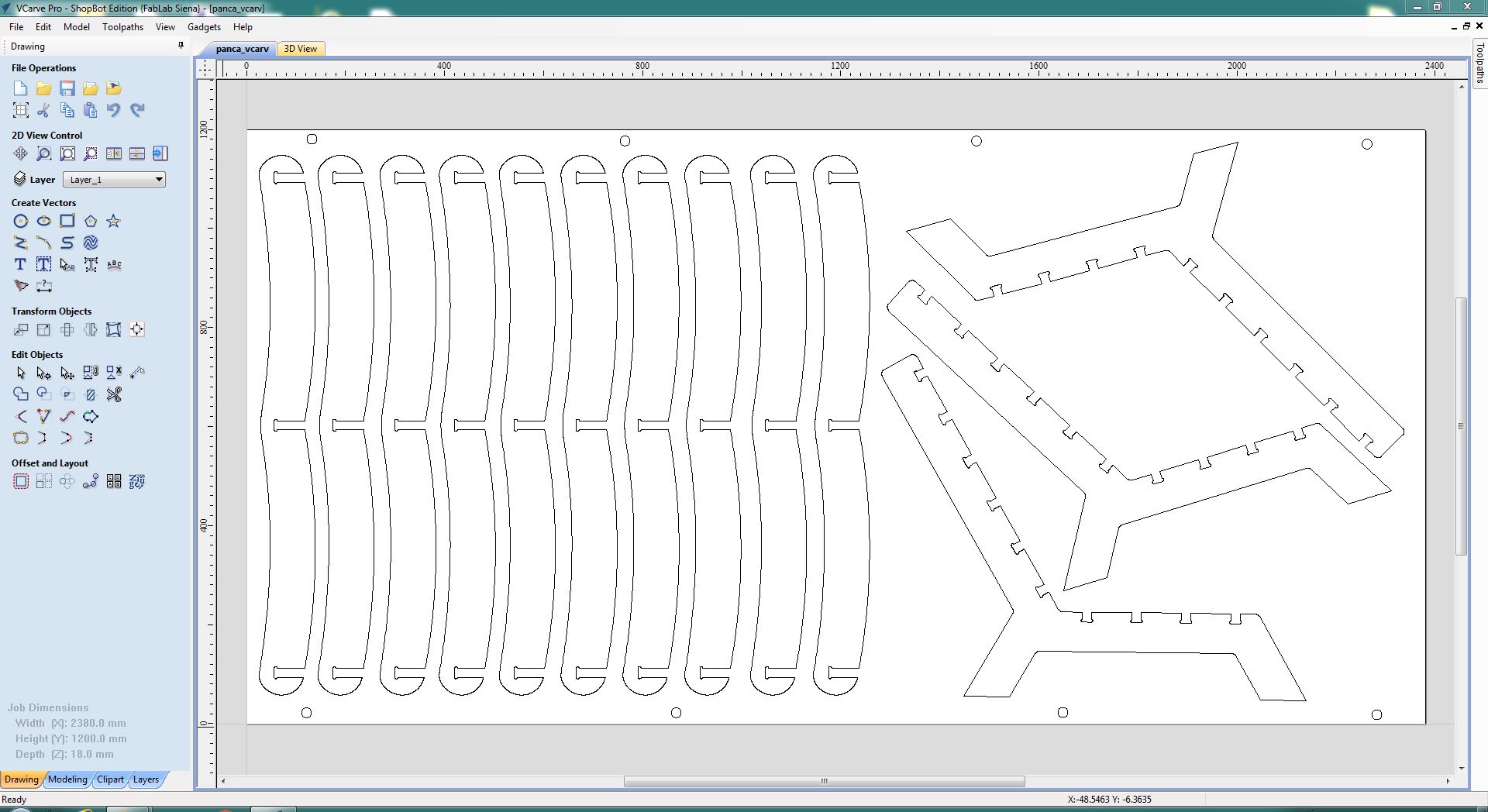
Then I added tabs to secure the pieces during the cutting process.
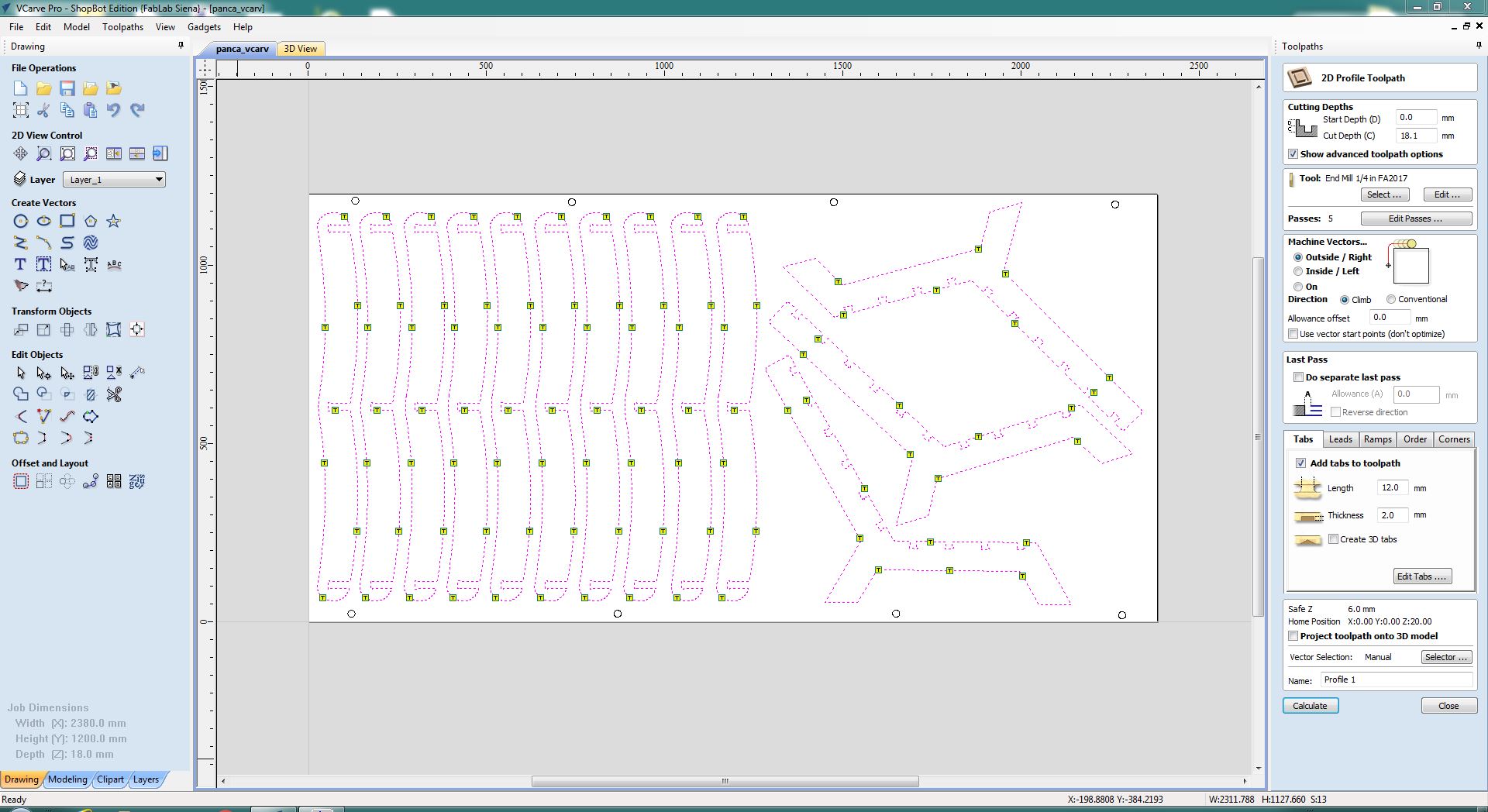
These are the end mill settings. To find the right ones you have to calculate some parameter in this way:
Feed Rate = rpm X chip load X number of cutting edges
Chip Load = feed rate / (rpm X number of cutting edges)
RPM = feed rate / (chip load X number of cutting edges)
Where the Chip Load is the thickness of a chip formed during the cut
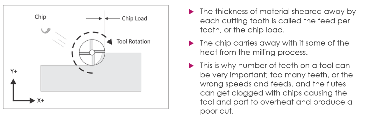
For each kind of material there is a chart that shows the Chip Load according to the tool series and diameter
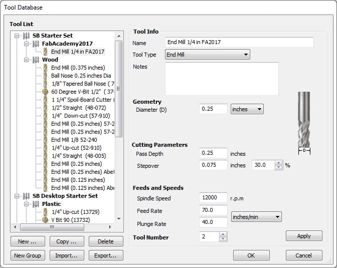
With other classmate we decided to reduce the feed rate to 70 inches/minute because the machine seemed to force too much.
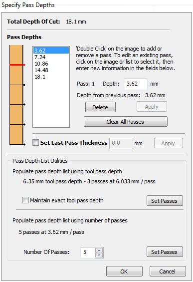
I also set the number of passes at 5 and the software automatically calculated the depth of each pass. The board thickness was 18mm so I set cut depth at 18.1mm to be sure the endmill didn't leave a bottom layer uncutted.
At this moment I could run the cut
View the original file here