
WEEK 10 – OUTPUT DEVICES
Weekly assignment
Add an output device to a microcontroller board you've designed and program it to do something
For this week's assignment I've decided to make the hello.servo.44 board since I'm going to use a servomotor in the machine I've designed for the group assignment, and I wanted to start managing this kind of motors.
As usual, I started by making a list of components I needed to assemble the board.
BOM (one for each):
ATtiny44 microcontroller
20MHz resonator
20uF capacitor
10K resistor
6-pin ISP header
3-pin male header (to connect the servomotor)
4-pin male header (to connect the power)
5V regulator
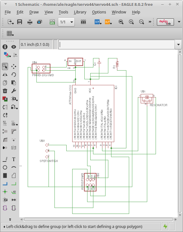
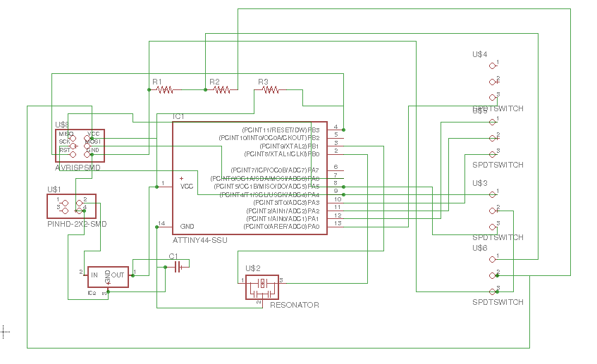
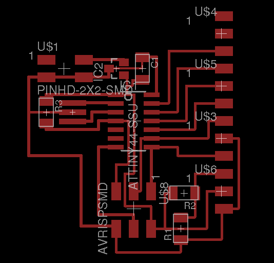
Then I moved to Eagle to design it. Starting from Neil's version I tried another regulator package (SOT 23) and so I had to redraw the related connection according to the minimum distance between pins and traces. Specifically I couldn't lay a trace between the in and out regulator pins, so I had to find other ways.
I also wanted to connect only one motor, so I included only one 3-pin header.
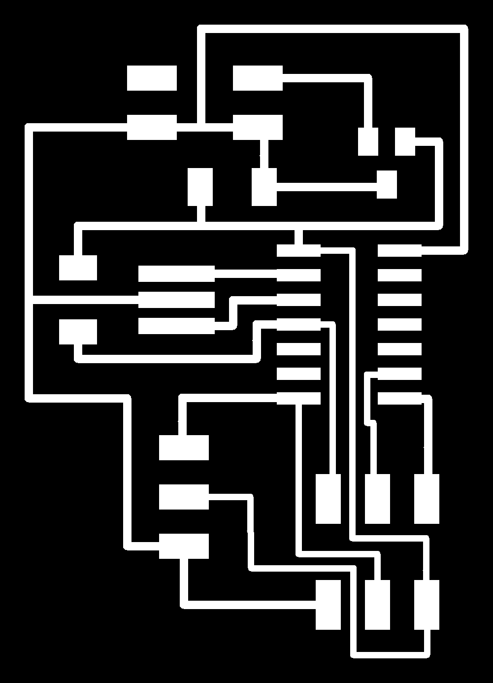
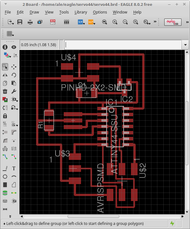
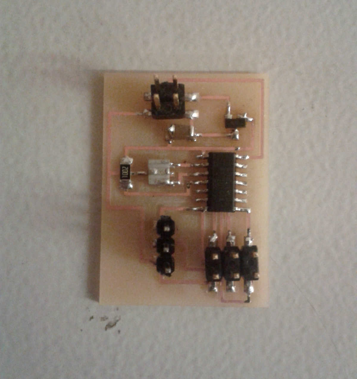
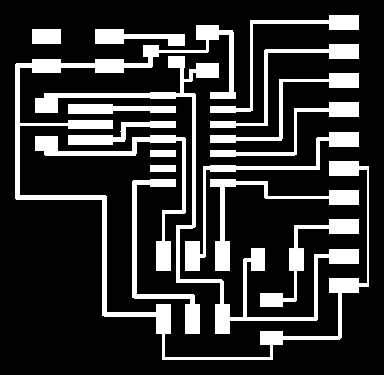
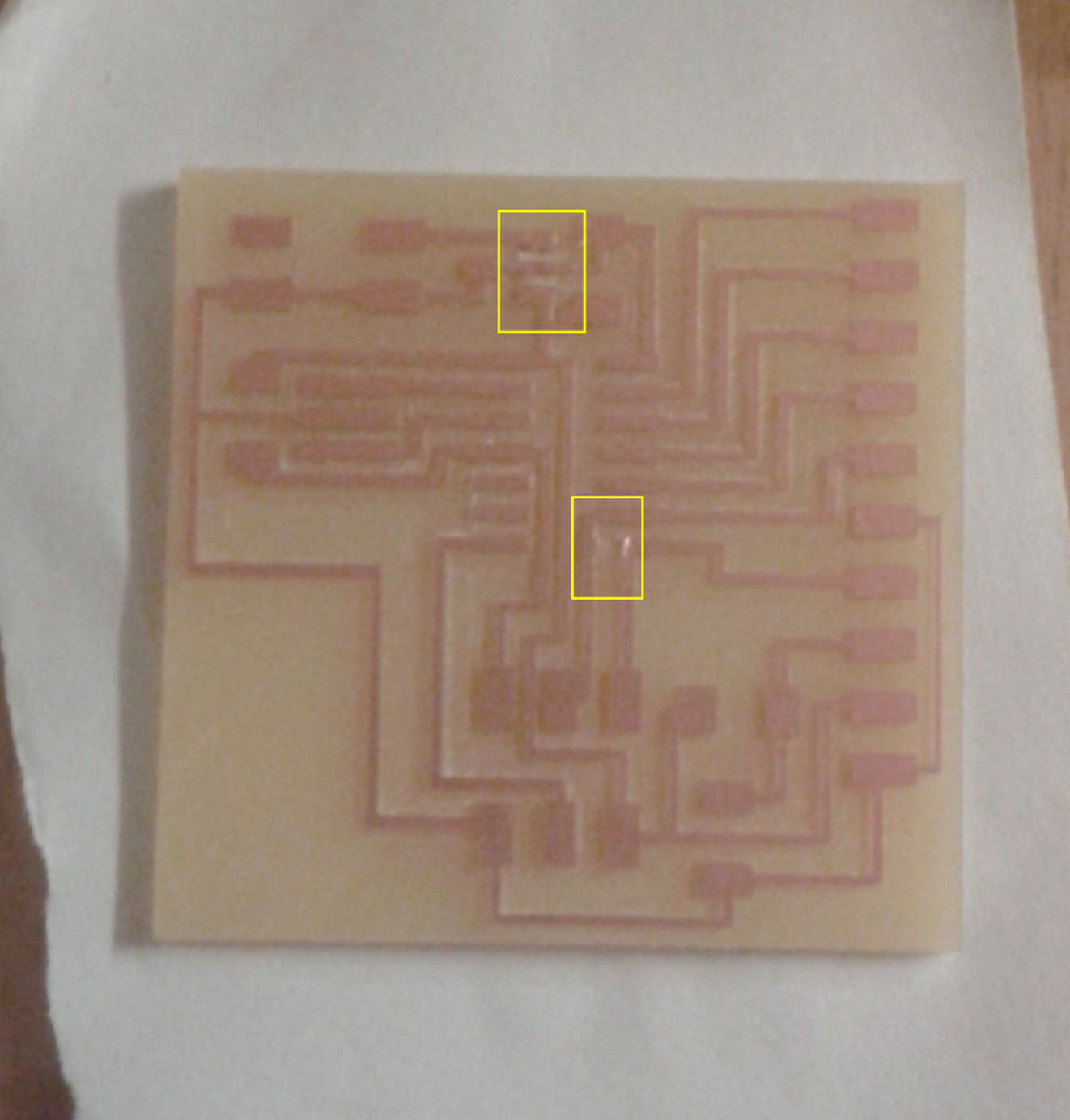
I created traces and outline .png files using Gimp and milled the board as I did in previous weeks
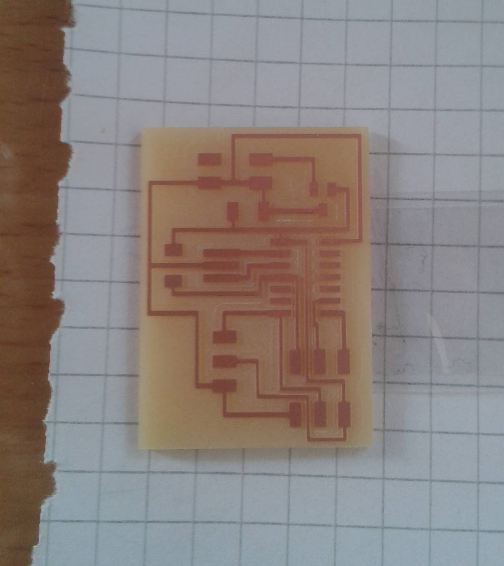
And then I soldered it
When I connected the hello.servo.44 board to my FabISP to program it I notice that the regulator heated up in few seconds. I found that it is normal for a regulator and I only tried to hurry to program it, so I could disconnect it as soon as possible.
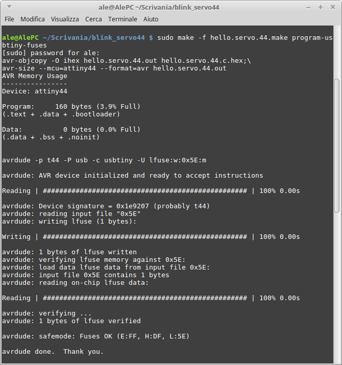
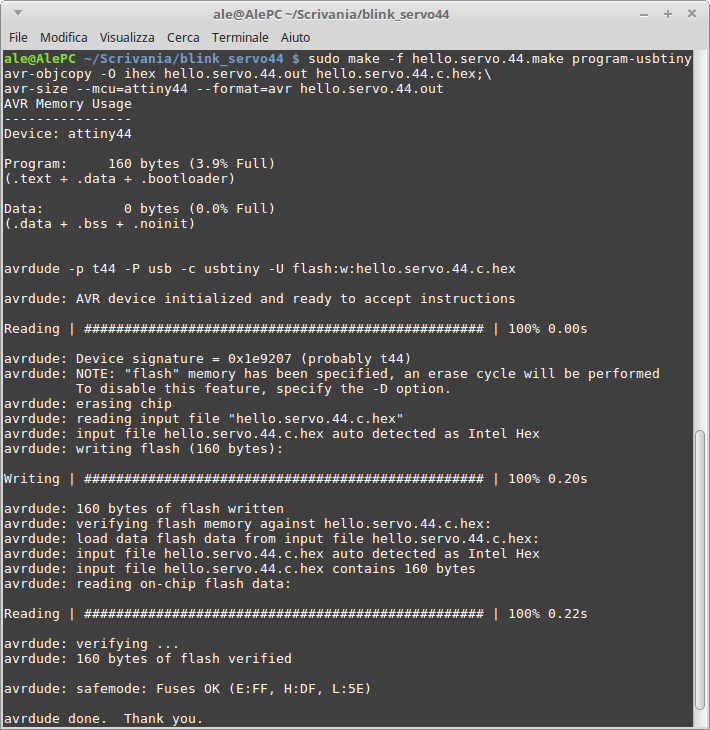
Fortunately everything went well at the first attempt (never happened before!).
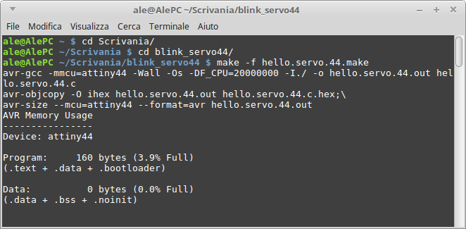
To quickly see if my board was actually able to move a motor I used Neil's C code for one motor.
Anyway I'm not enough pleased with my work, I want to study deeply motors (even stepper) and explore more programming. But this needs a lot of time...
Update 2/5/2017
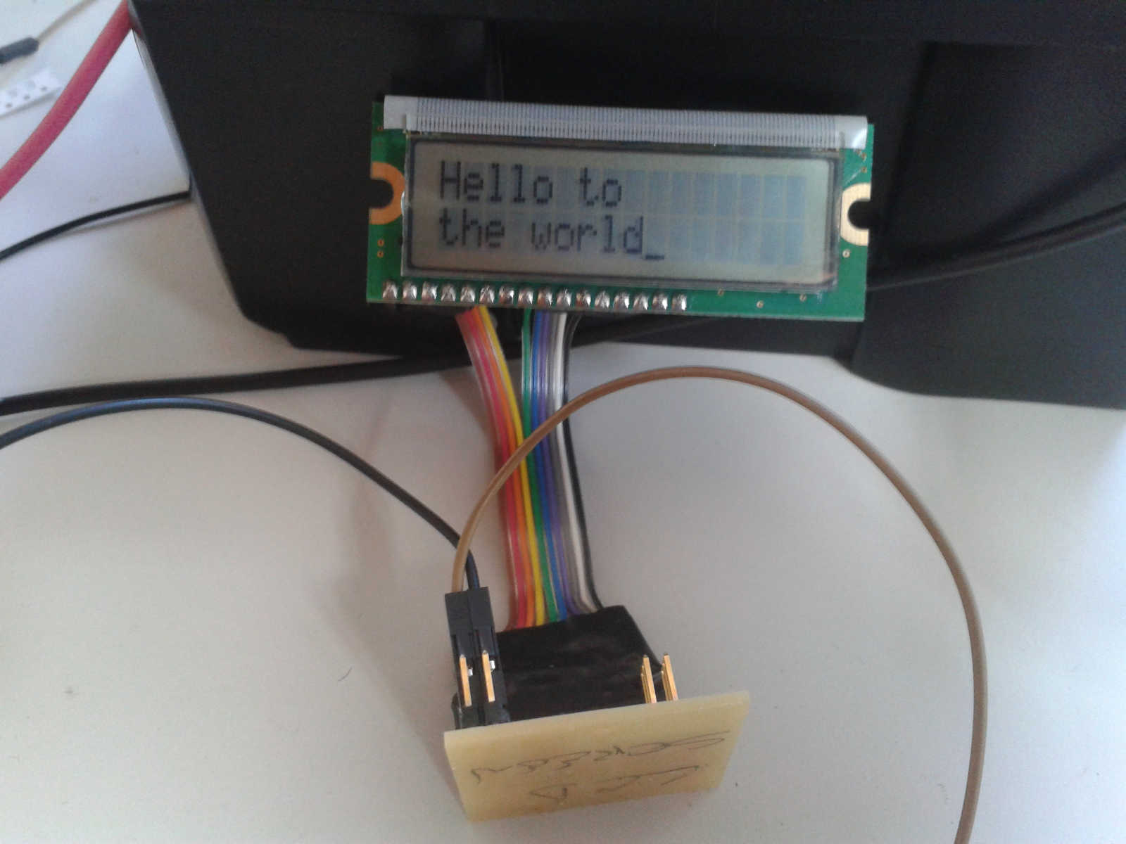
LCD board
In my opinion LCD screens are very usefull devices so, since I had some time during the input device's week, I decided to make a LCD board
I started again from Eagle to design the board
The LCD screen I used has 16 pins but I needed only 10, so I designed my board with only those pins I was going to use
In Eagle I couldn't find the specific kind of pin header I needed, so I laid more and then I removed the surplus (only two on the top) on Gimp once I moved to set traces and outline files
To do this I only had to select the area I wanted to keep and then click on "crop to selection"
After the milling process I had a bad surprise, three pins were connected to some traces they should not be

So I removed these connection by hand with a cutter and tested with the voltmeter to be sure everything went fine
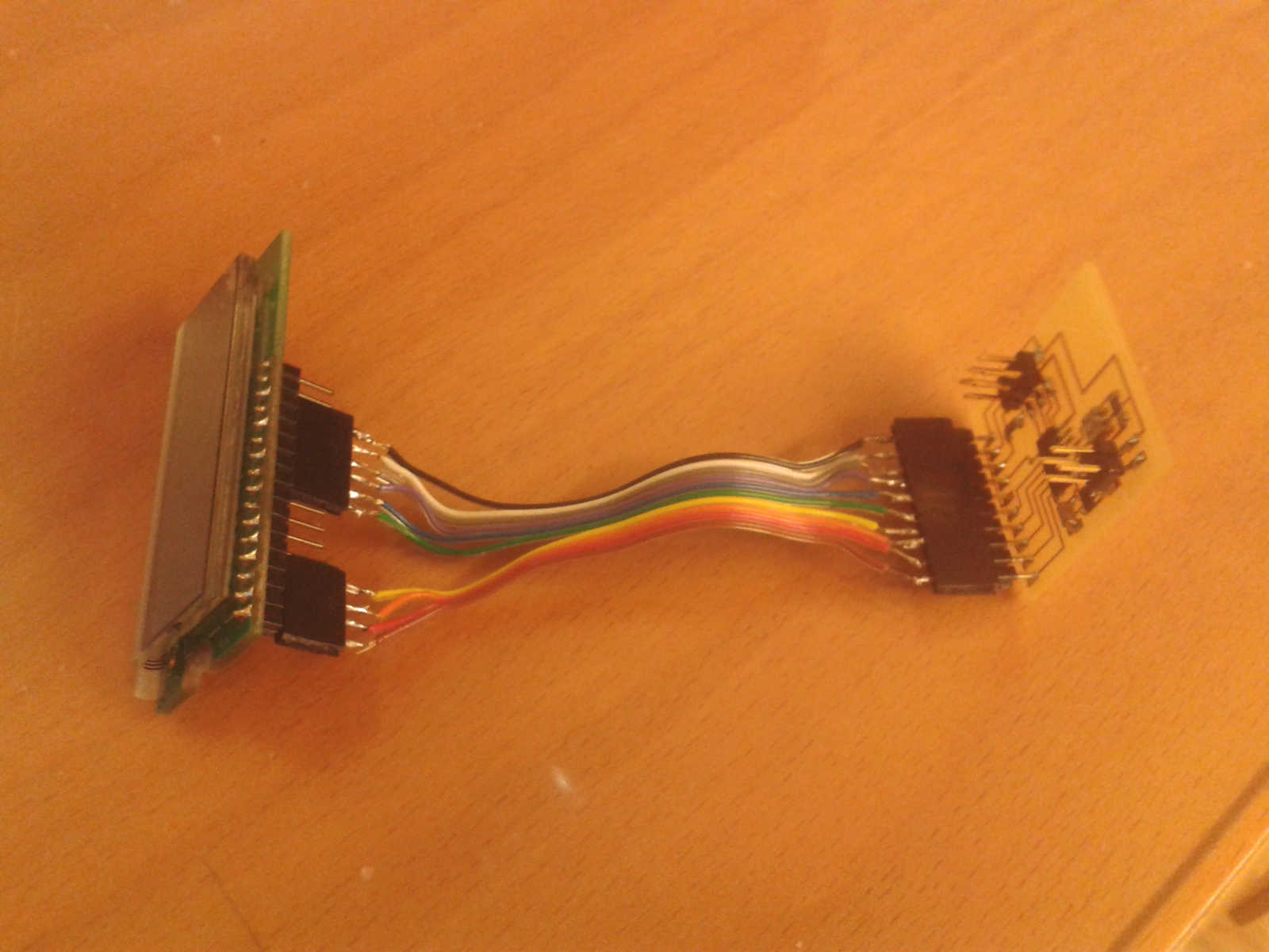
Making the connection cable
Due to my board design I couldn't connect it directly to the LCD screen, I necessarly needed a connection cable. But I already knew when I designed the board, beacause I used LCD pins from 1 to 6 and from 11 to 14
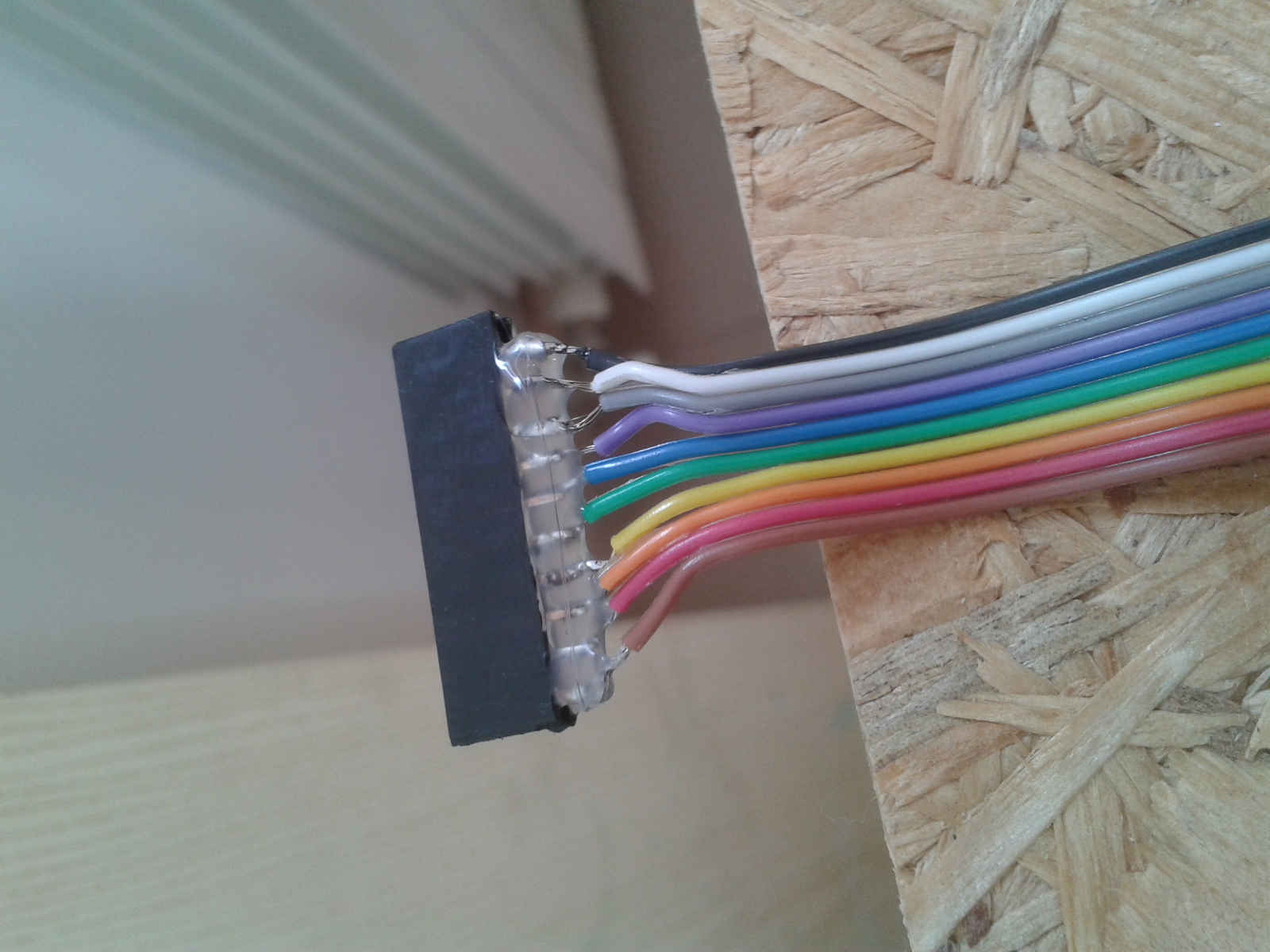
So I had the opportunity to solder my first cable
I checked all connections with the voltmeter, and since they worked I covered them with hot glue to isolate any connection to each other. After that I covered everything with the insulating tape
Then I moved to program the board using Neil's C code and make file
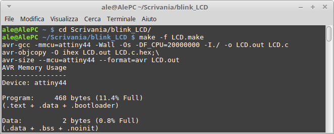
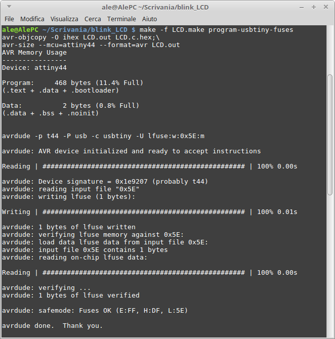
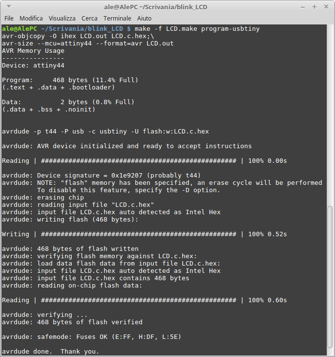
Eagle and program files here