
WEEK 11 – MACHINE BUILDING
Weekly assignment
Automate your machine. Document the group project and your individual contribution
My role in this work was to design the vertical frame in all of its parts, including the X/Y axis, the servomotor and the boxes frame.
During this week I continued the machine design, solving problems I've found during the real building and adding other components I needed.
I also modified some parts of the original model.
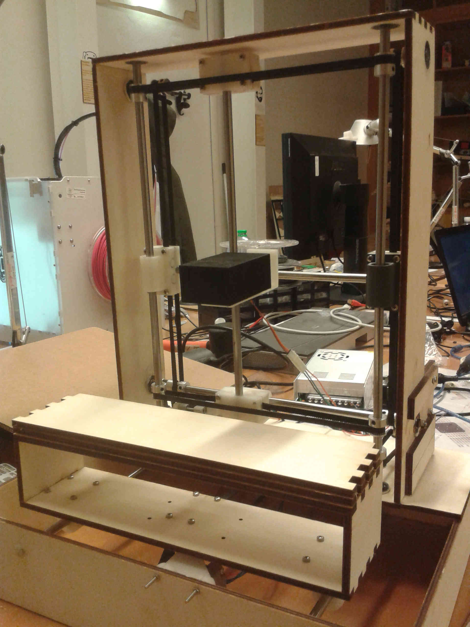
One of the first thing I did was to design a frame for the X/Y axis
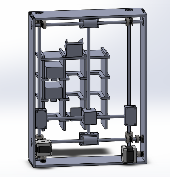
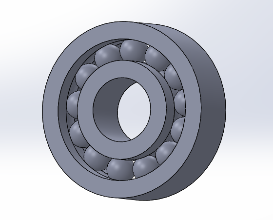
I designed it to be made with plywood, laser cutted and press-fitted. To do this I modeled the 3D version, then I selected a face and saved it in DXF format. In this way I had a file ready to be cutted. I also added holes for the ball bearings.
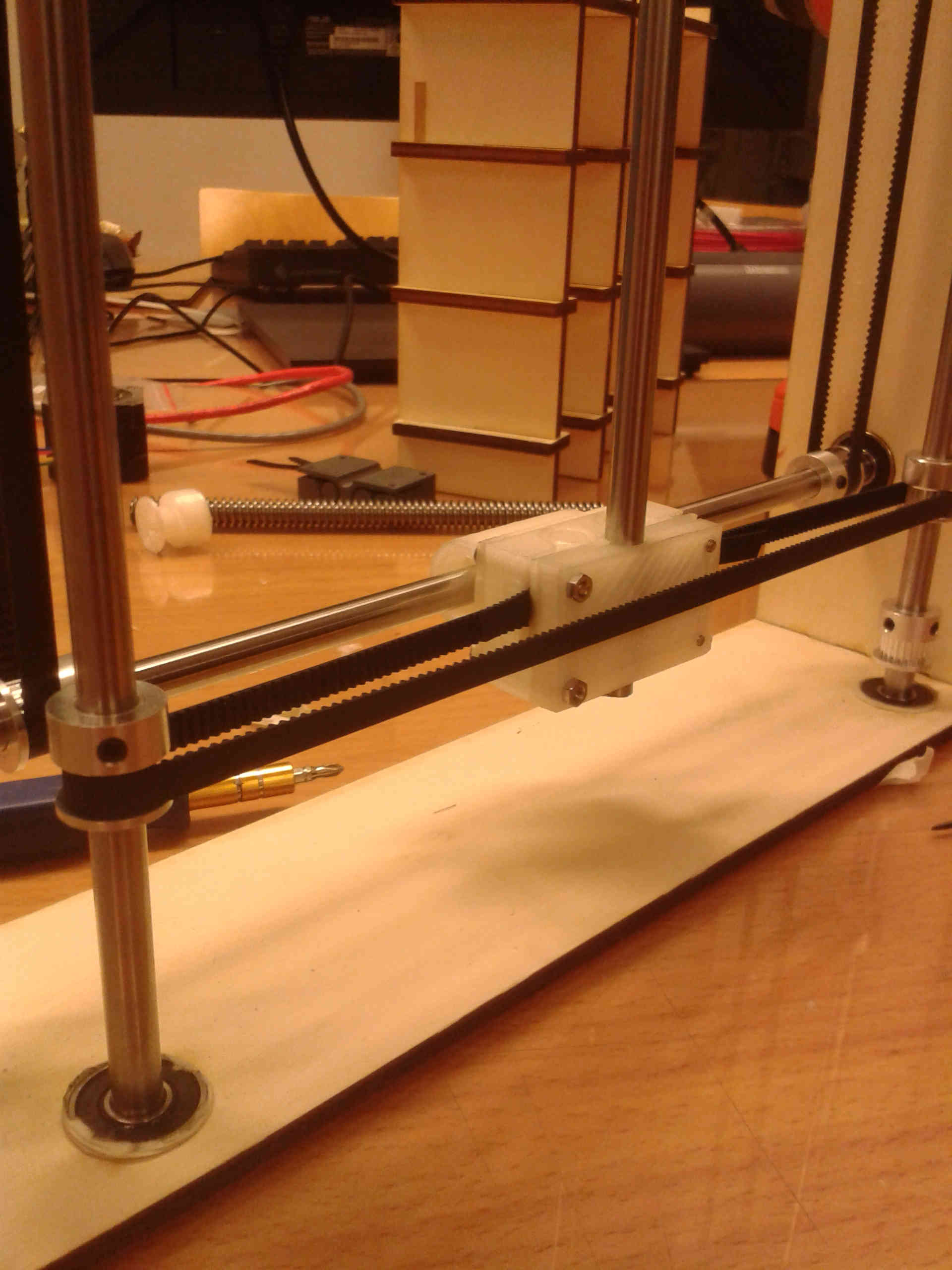
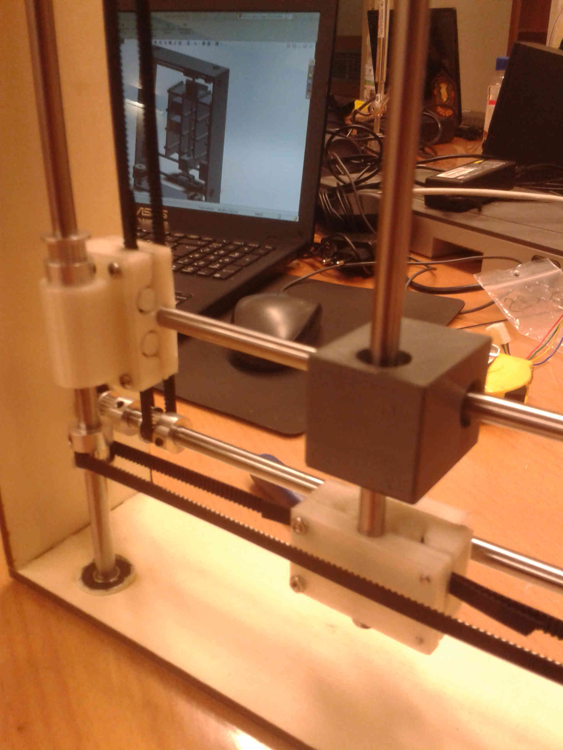
In the previous picture you can also see the belt blocks I designed and assembled. It is composed of three parts joined together by screws.
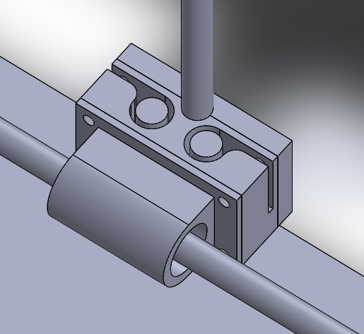
I found this shape on Thingiverse where I browse to get inspired about some components I could use. I thought it would work so I re-designed it according to my size. But when I moved to use it actually, I found it not easy to use. It was particularly difficult to fit the belt in its place. I'm sure there are many others smarter.
So I moved to add stepper motors to see where I could place them and eventually adjust the frame size. I found a 3D model of Nema 17 on Grabcad and I modified it to my size (we used a shorter version).
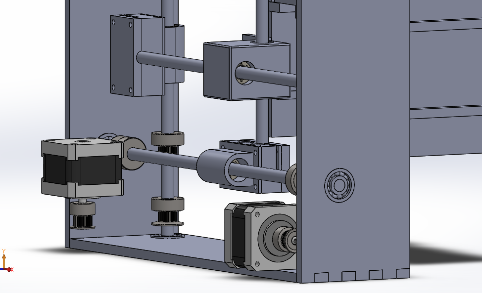
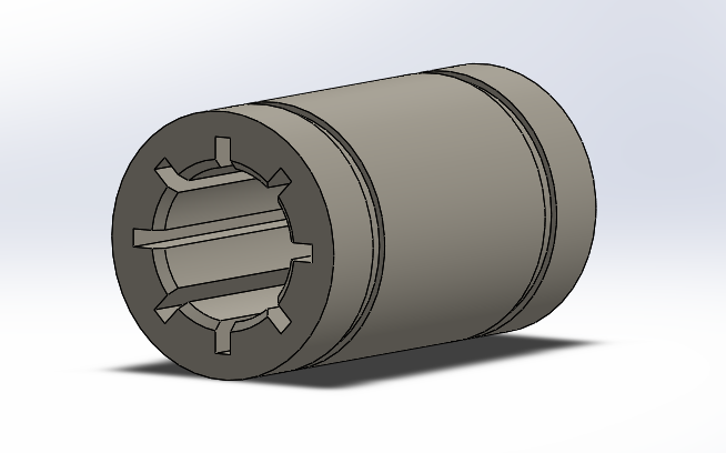
On Grabcad I also find model of linear and ball bearings I could modify (if you didn't understand yet, I modeled EVERYTHING!)
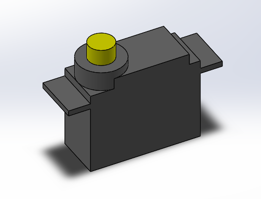
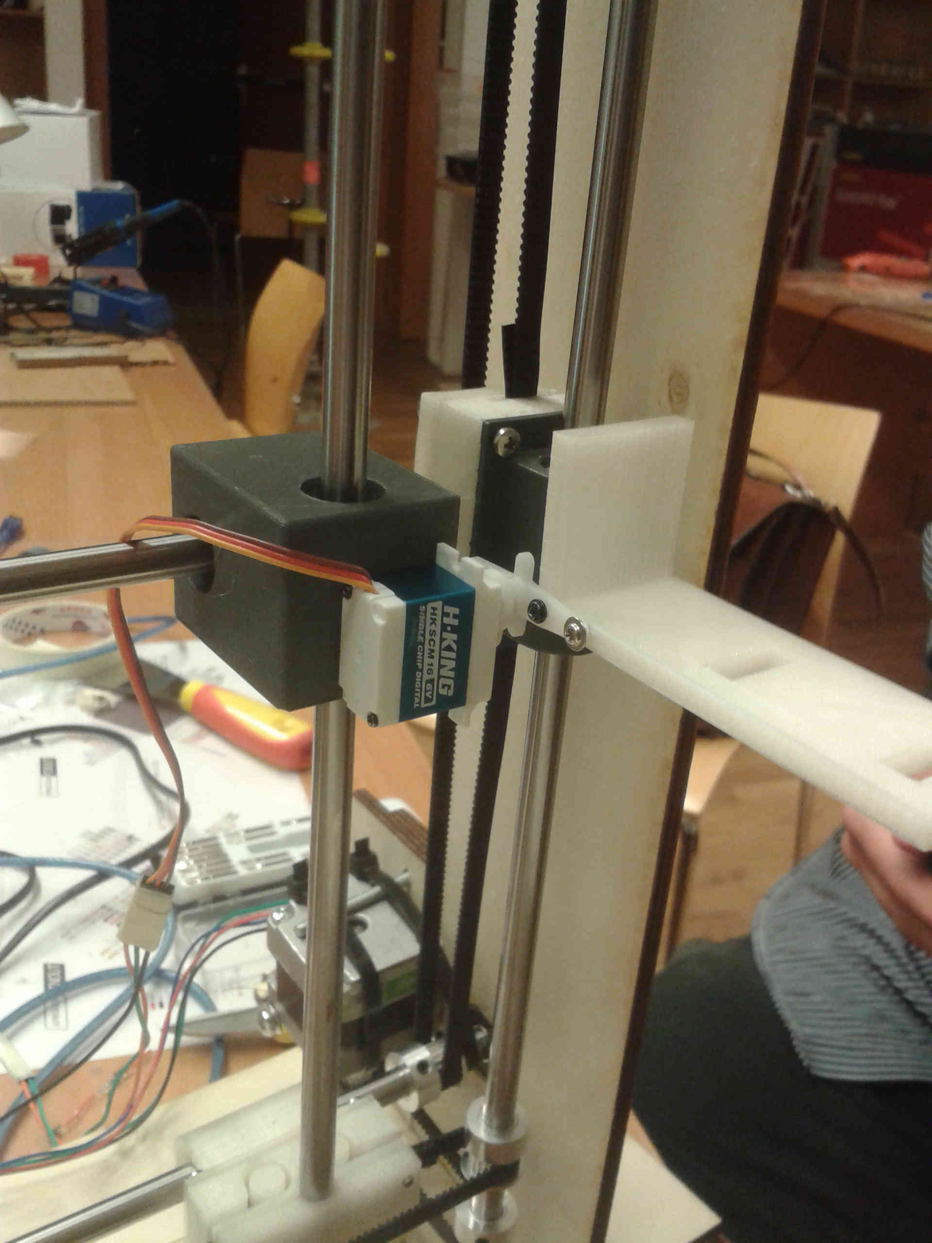
Then I continued with the servomotor and related components.
And this is the real assembly
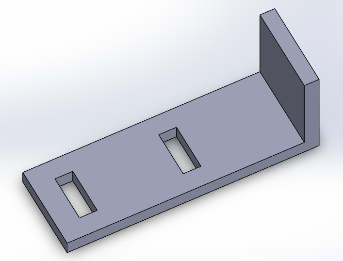
The fissures on the plate you can see in the previus pictures represent another update I made.
I needed a way to hold the box when it was bended, but I wanted do this in the easiest way possible and without using other technologies (at the beginning we thought at electromagnet or something like that, but we soon abandoned the idea)
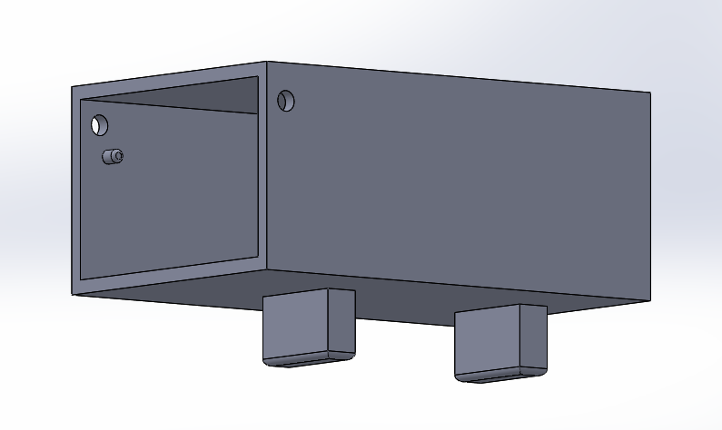
To do this I added two extrusions at the bottom of the boxes, calculating also a tolerance between male and female.
Here is a picture of the plate holding a box.
About the boxes frame, I already modeled it in the mechanical design week, so I only had to cut it and verify if the press fit worked...
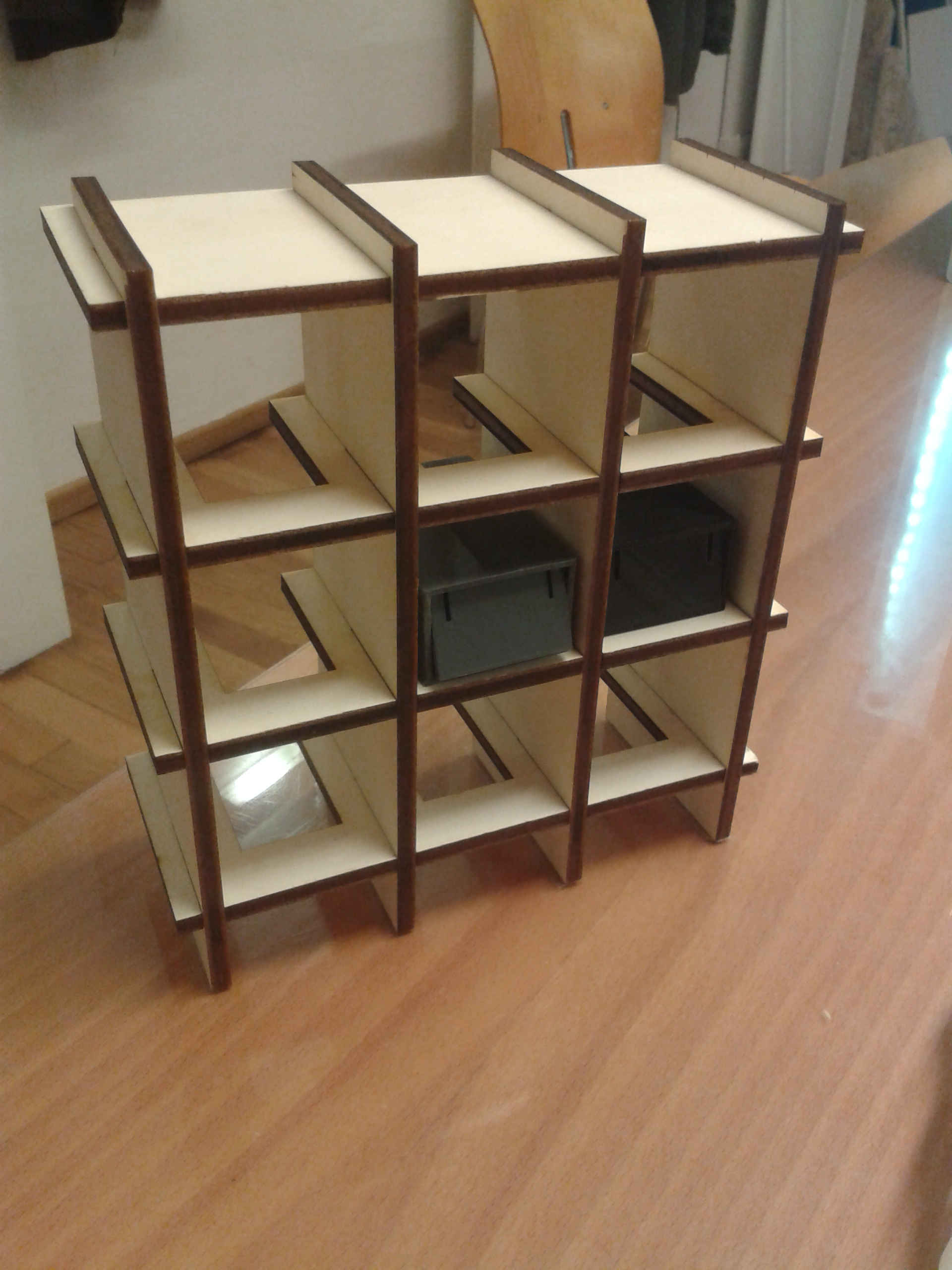
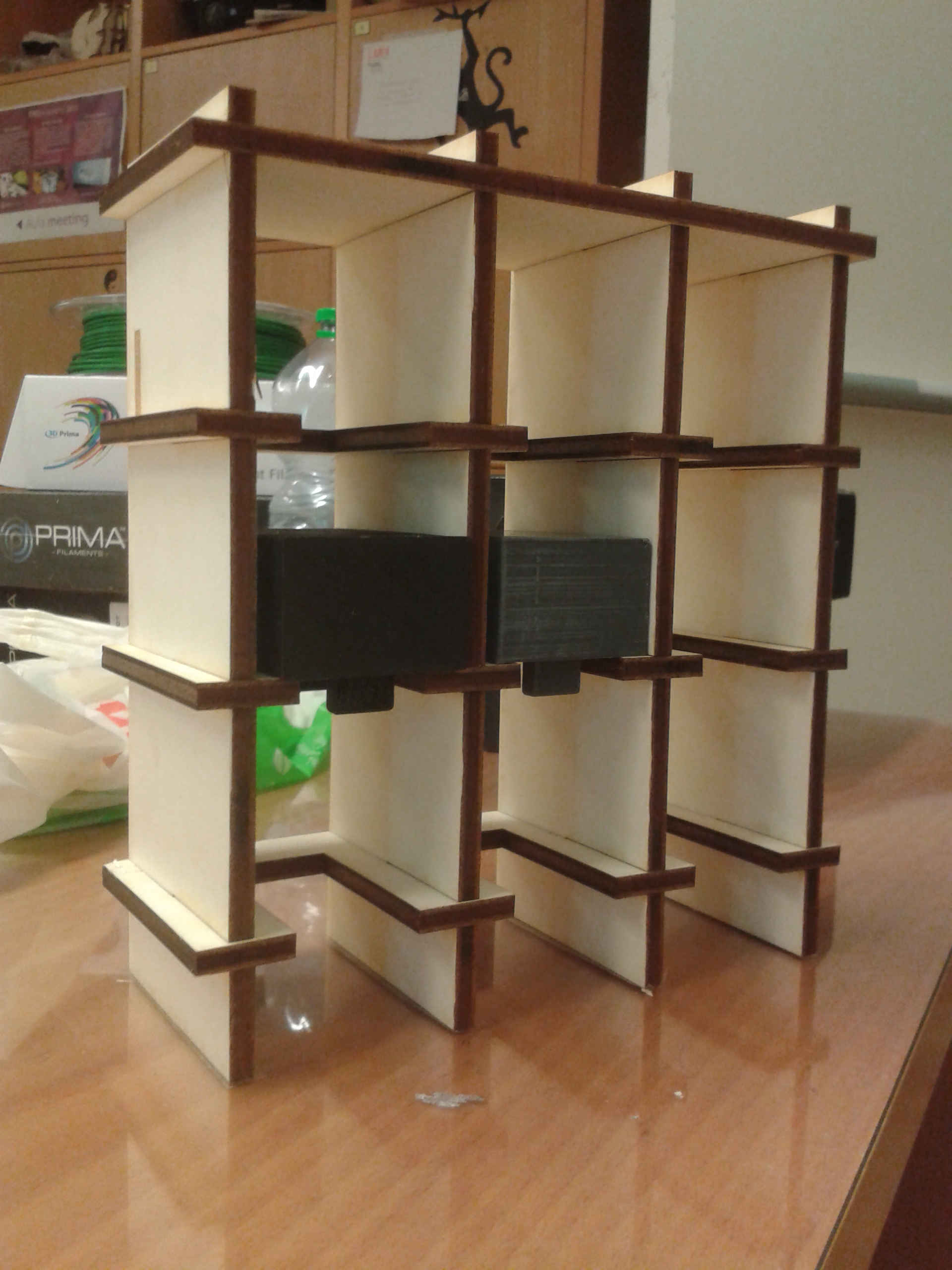
And it did very well, this is probably the best press fit I ever made!
Before to cut I made some kerf test and I found it at 0.05mm with a plywood board of 5.8mm thickness. Also the tolerance between the frame fissures and the plate width was right. In fact as you can see the slots have a free space in the middle to let the plate hook the box and lift it up.
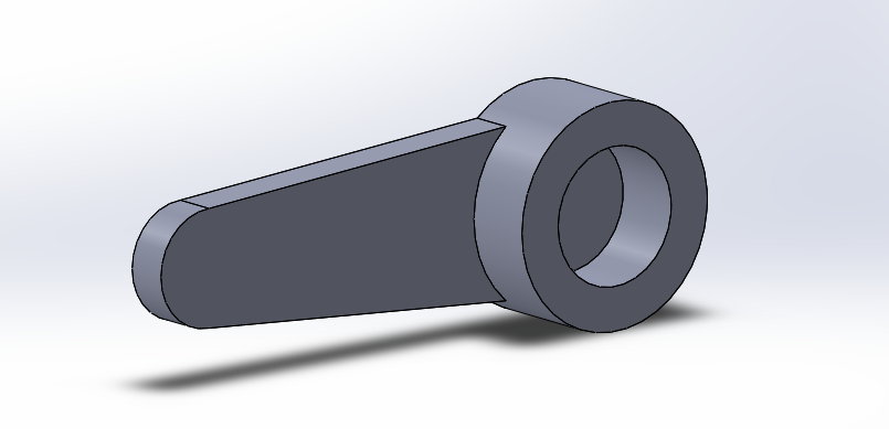
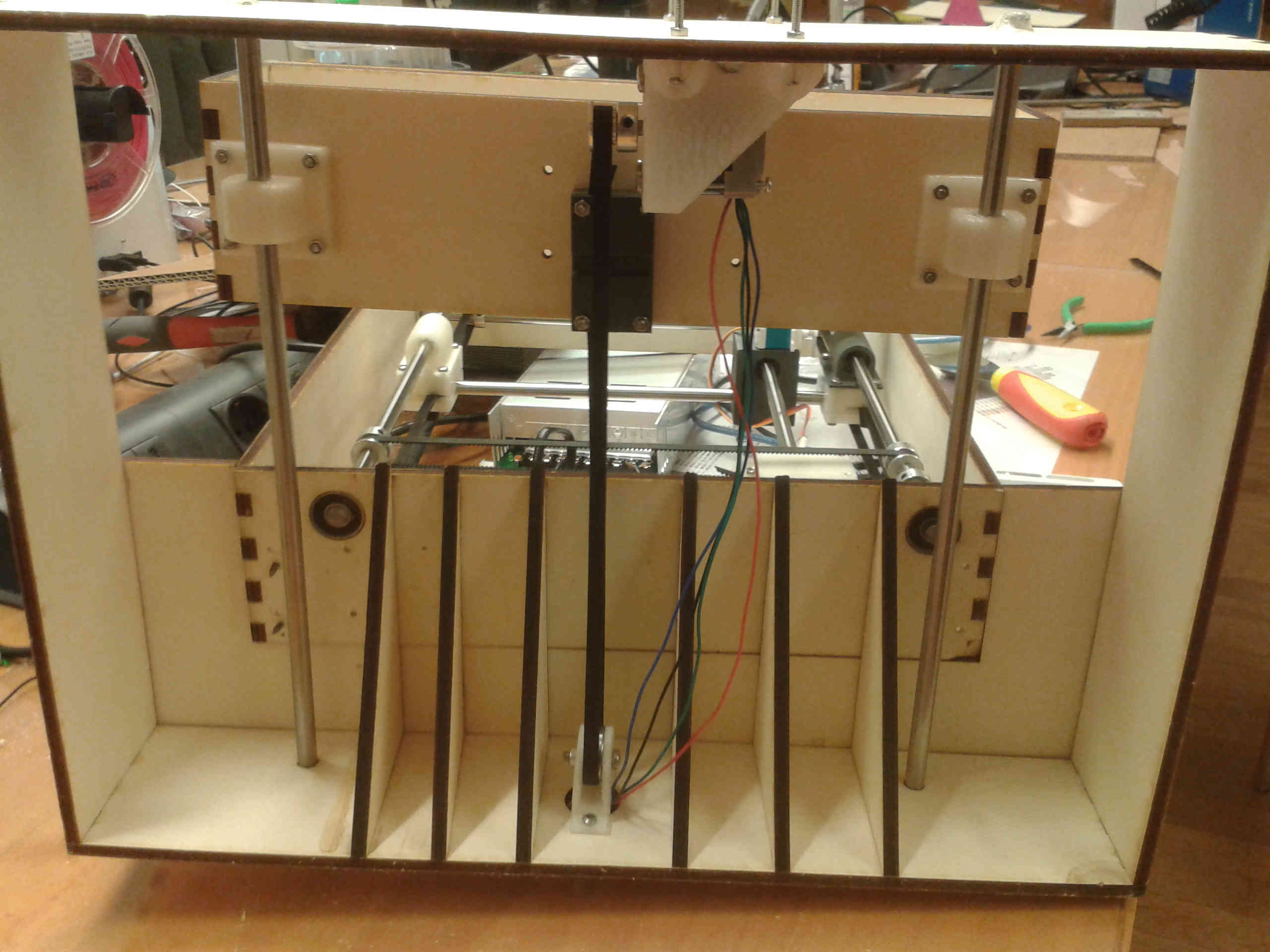
The last thing I did was to model a component for the Z axis.
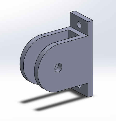
This is a support for a ball bearing whic guides the belt for the Z axis.
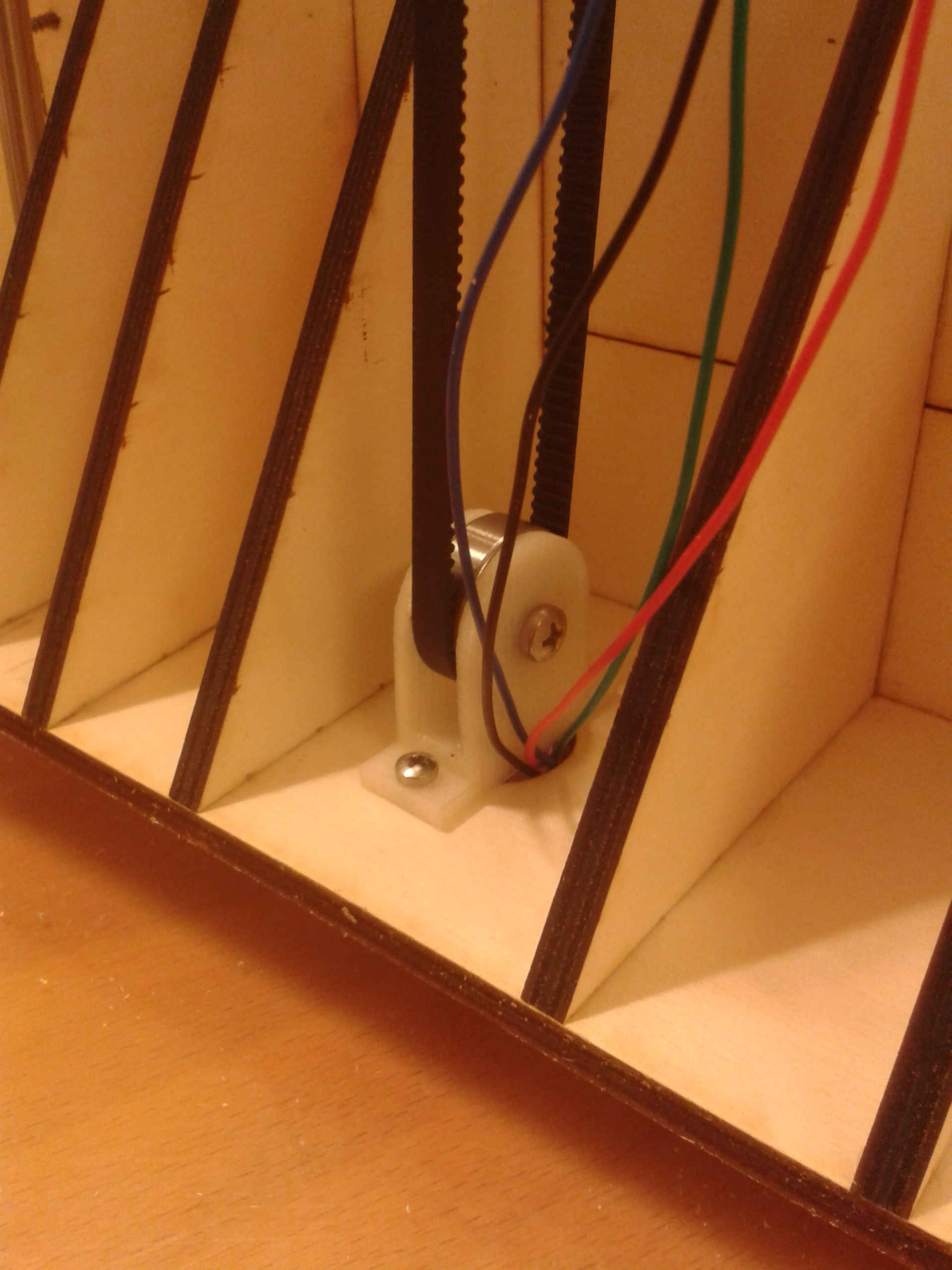
This is a solution we had to find in extremis, because at the beginning we wanted to move the Z axis with a threaded rod, but we didn't have the right component in time, so we changed the model to move the Z using a belt
This is a bottom view of the Z axis.
Here you can watch some attempt of move
And here there is a link to the group page
In regard to the movement I've found a useful tutorial on the output device week's page of my classmate Chiara to have an idea of how G-Code works, so I was able to control the machine.