
WEEK 5 – 3D SCANNING AND PRINTING
Weekly assignment
Group project:
Test the design rules for our printer
Individual project:
Design and 3D print an object that could not be made subtractively
3D scan an object
3D Printing
This week’s assignment was to design and print an object that could not be made subtractively. So the first thing I thought at was something insert in a container. I didn’t want to make just a sphere in a box or a cilinder in anything else… So I started to think at what in real life is actually made in this way, or it just could be.
There are many things still existing that have parts included in a bigger shape (think at a light bulb, for example) and if you want to make it as a whole piece you have a good chance to try a 3D printer.
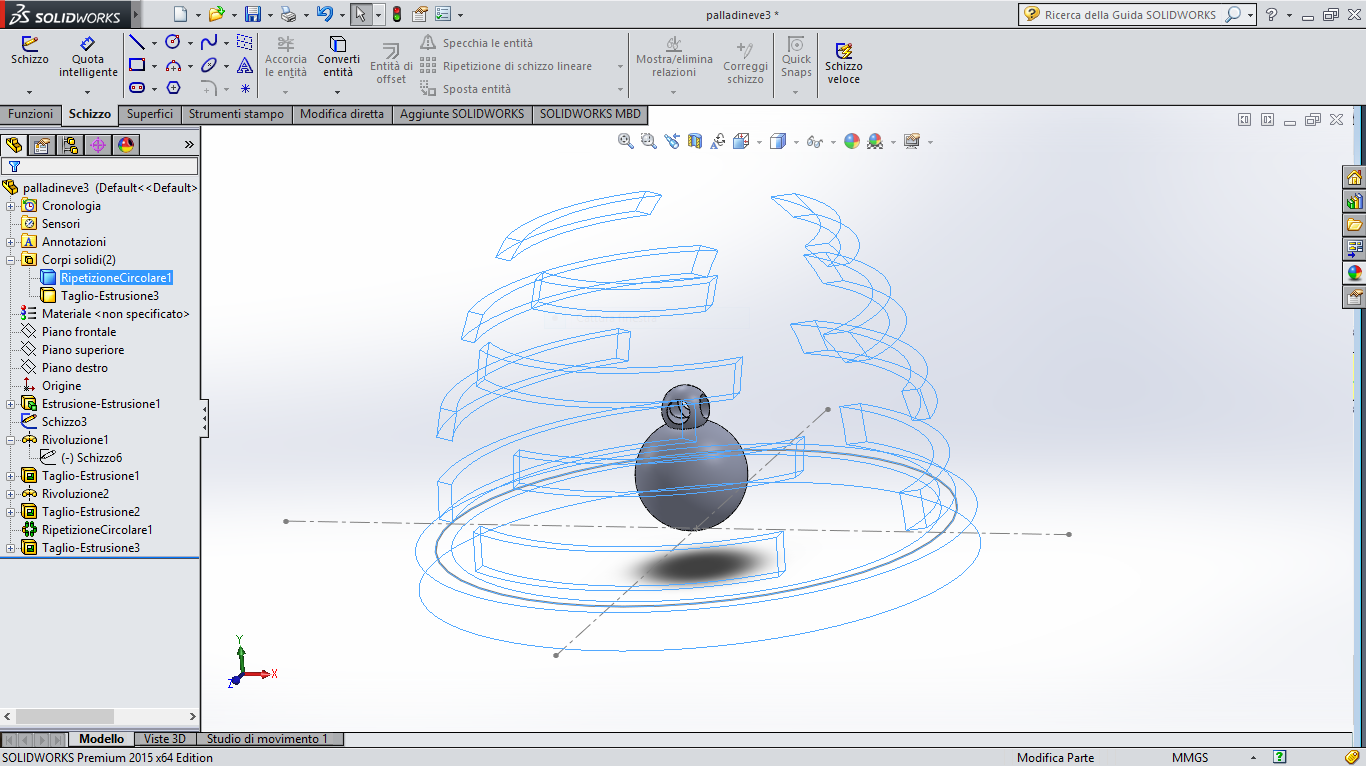
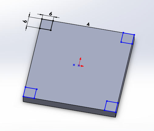
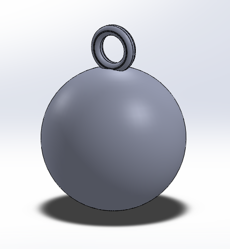
My first idea was to make something like a snow globe and I intended to realize the sphere like a cage, so the inner part could be visible.
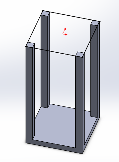
To make the design I used Solidworks, and I had quickly problems to make a rounded cage. So I moved to another strategy, I made a full dome and I insert a few openings.
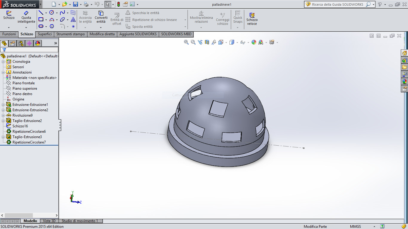
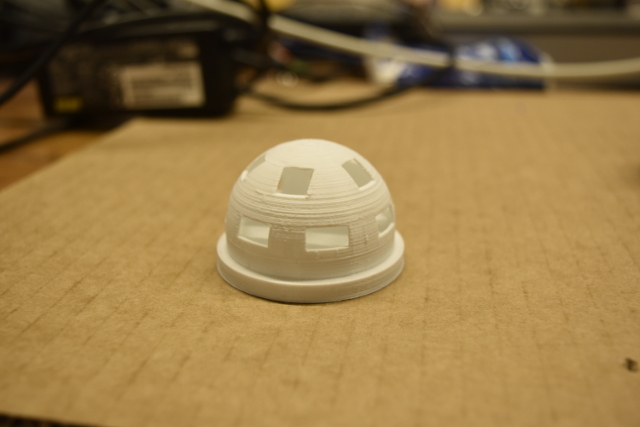
This is only a test, for this reason there isn’t anything inside the globe. Anyway I could found the shape well printed. I only noted that the upper edge of the holes showed very small inaccuracy with one or two filament strings not completely joined.
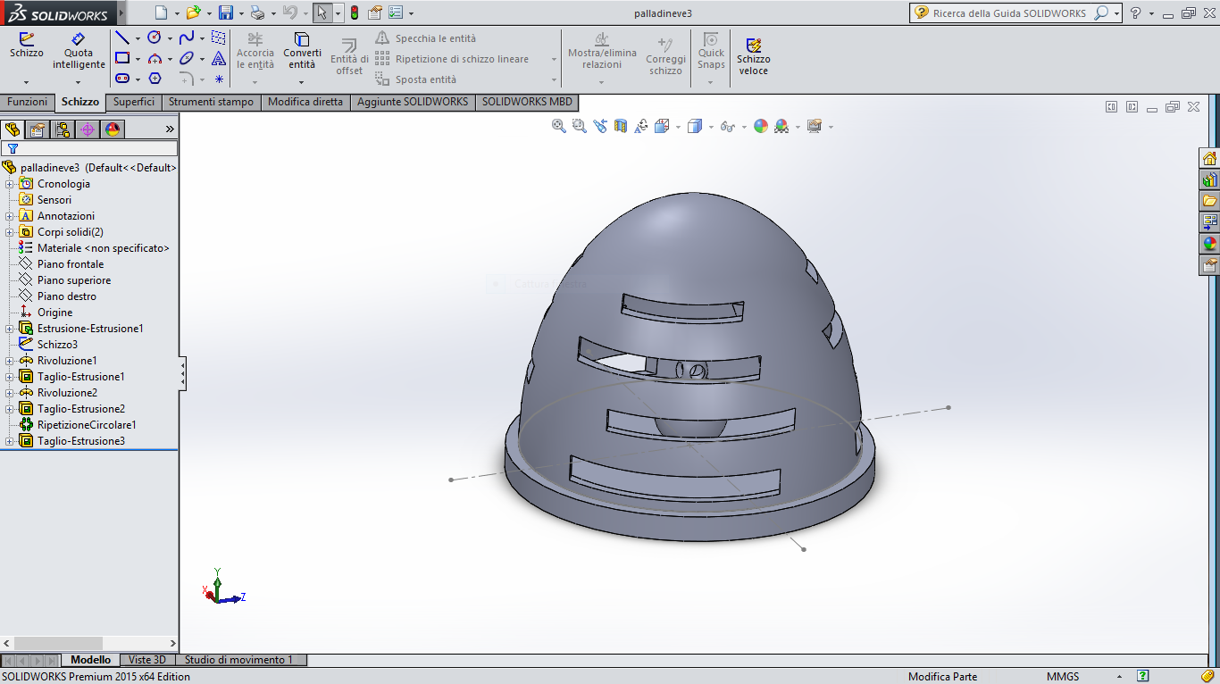
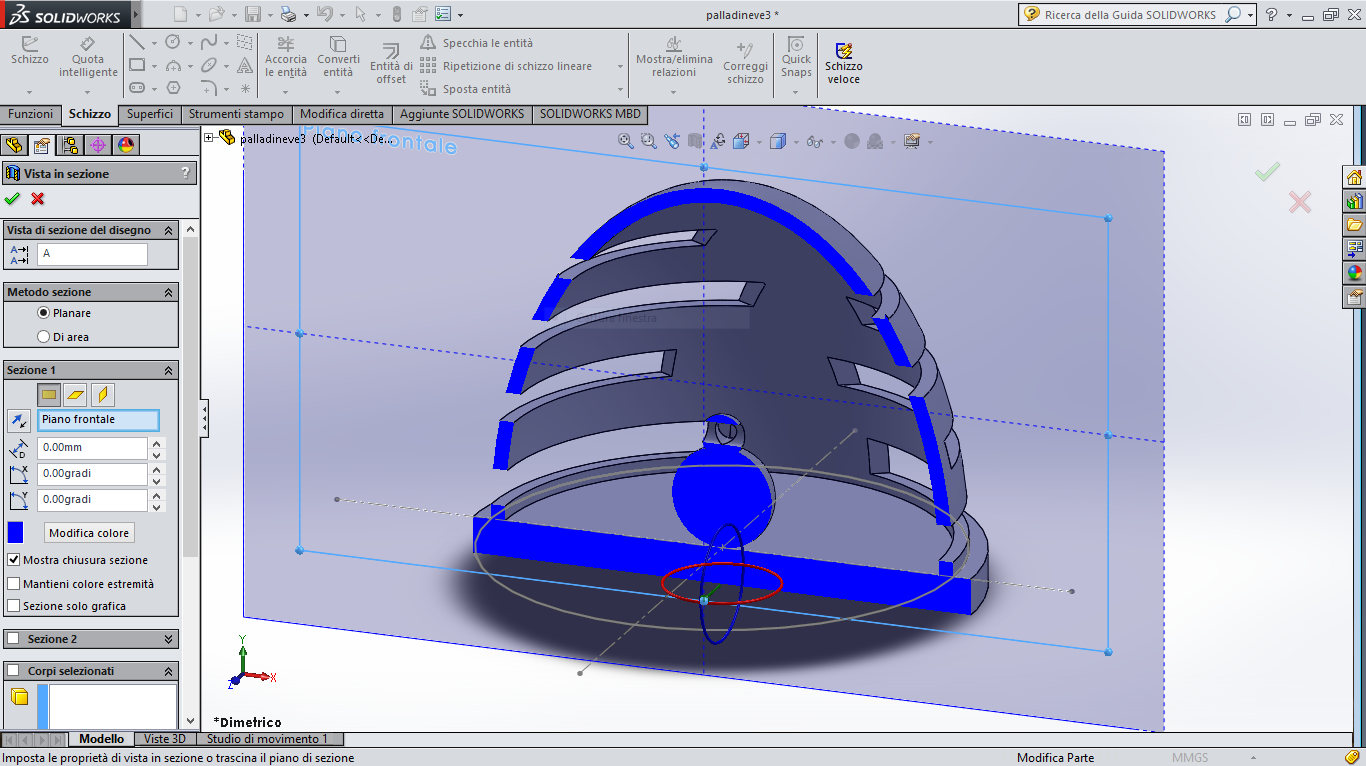
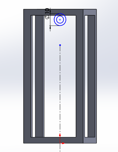
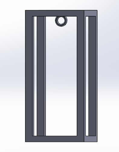
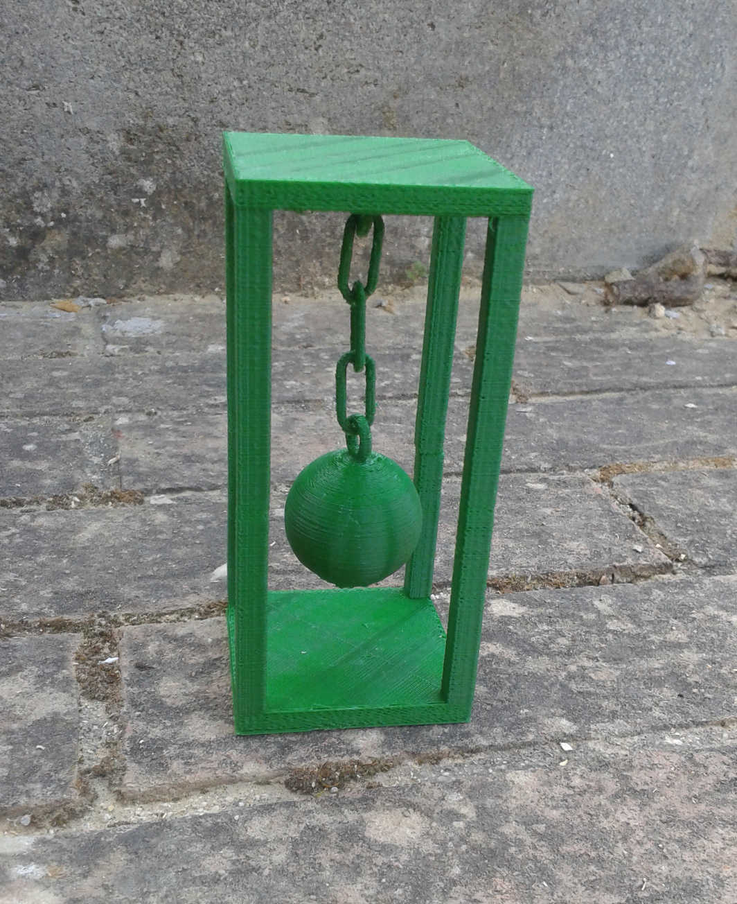
I was not satisfied with the visibility of the internal, then I tried to make an alternative version, by making the dome taller and inserting more fissures. This time I also placed an object in the middle. Now the design no longer looks like a snow globe, but it was not my main goal, so I didn't care.
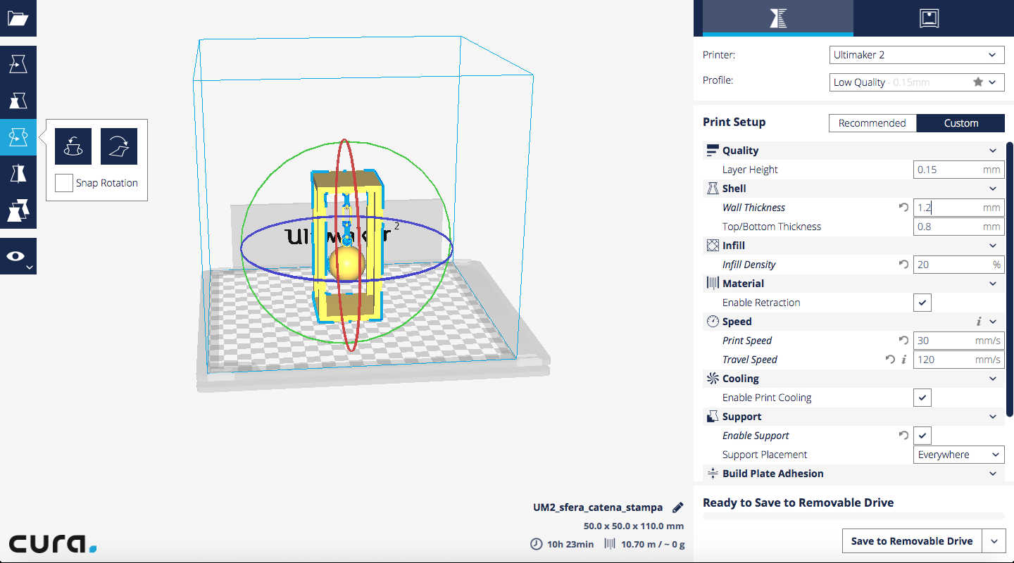
Then I started to print it with a Ultimaker2 setted with an old version of Cura, the setup was the best working we found during the group test.
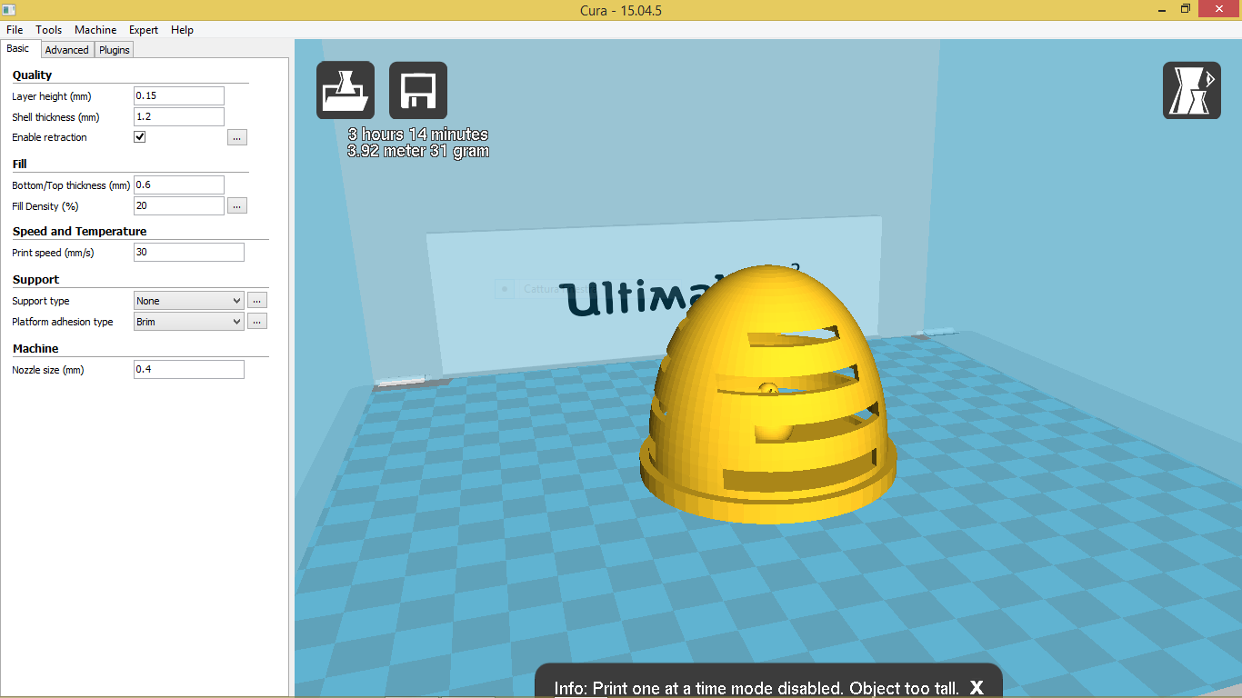

To print with Cura I had to generate a .gcode file that I copied in a SD card and I insert in the 3D printer.
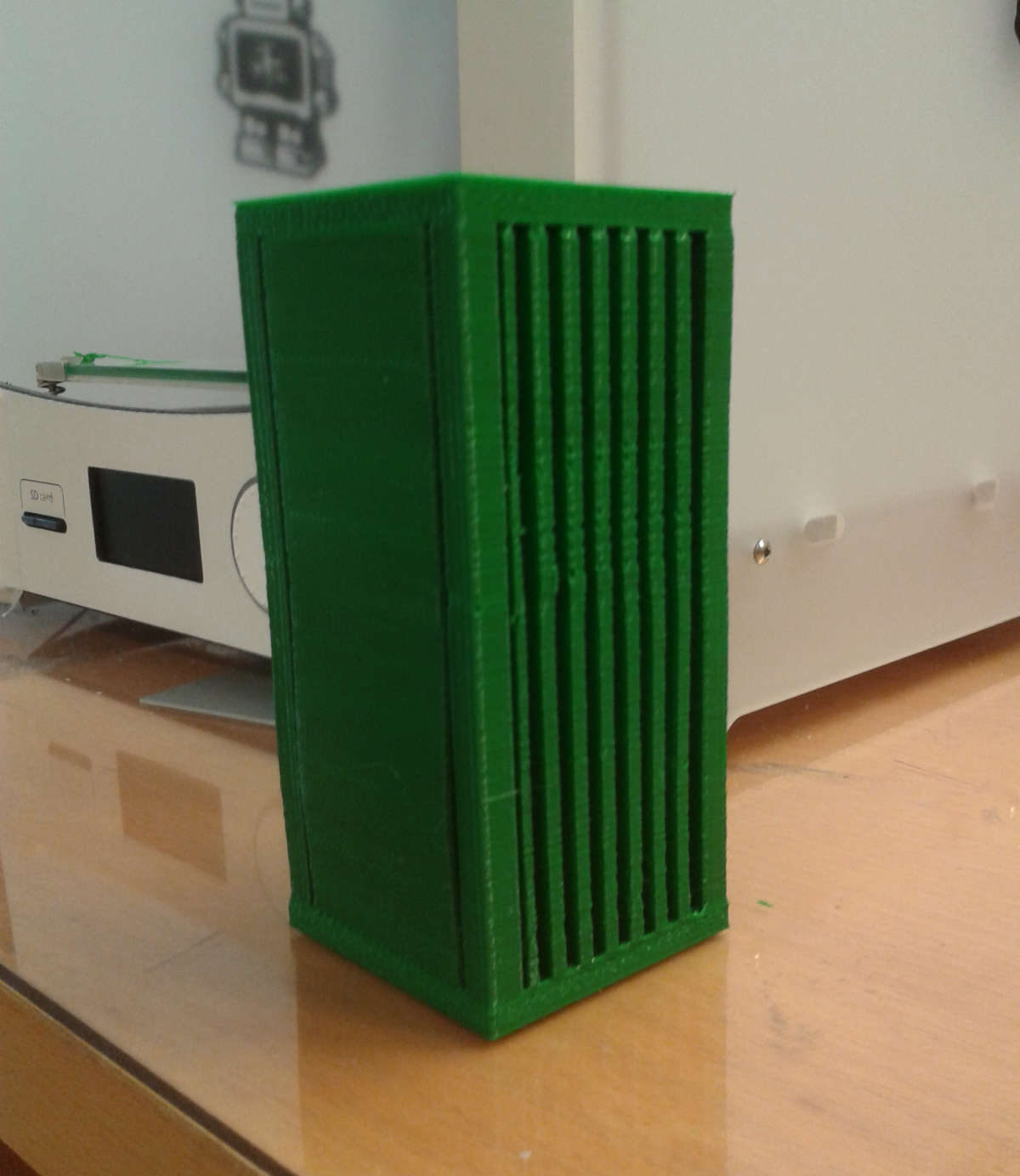
This is the result
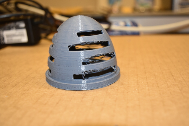
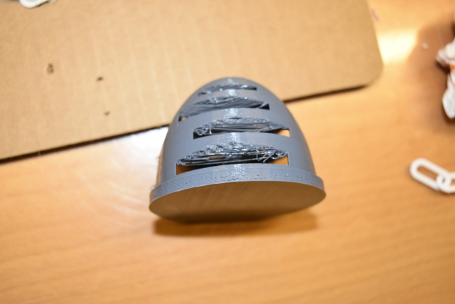
As you can see I had several and importatnt problems with the fissures. The small inaccuracy of the previous version became a catastrophe!
This is a matter we tested in the group project, it is called bridge test. It refers to the ability of a 3D printer to print a layer suspended between two frames. In the first attempt the distance between frames was significantly lower, and I had minimal effects. But this time the distance the nozzle had to cross without any support was too much.
My instructor explained me why very well. He told me this appens because the nozzle can only print straight filaments to connect two frames, and when in the model there is a too large distance to be covered it starts printing in this way even if the shape is curved.
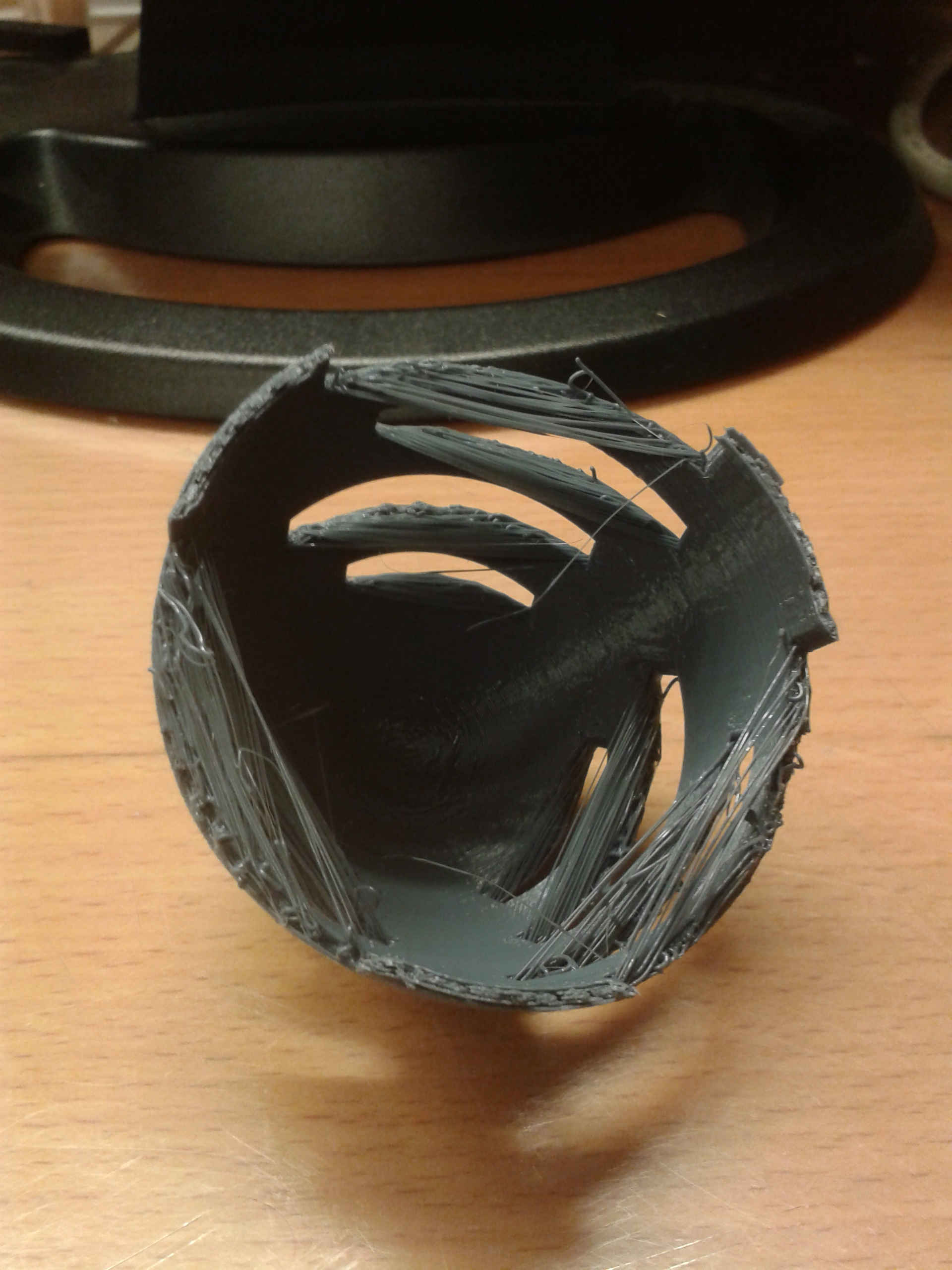
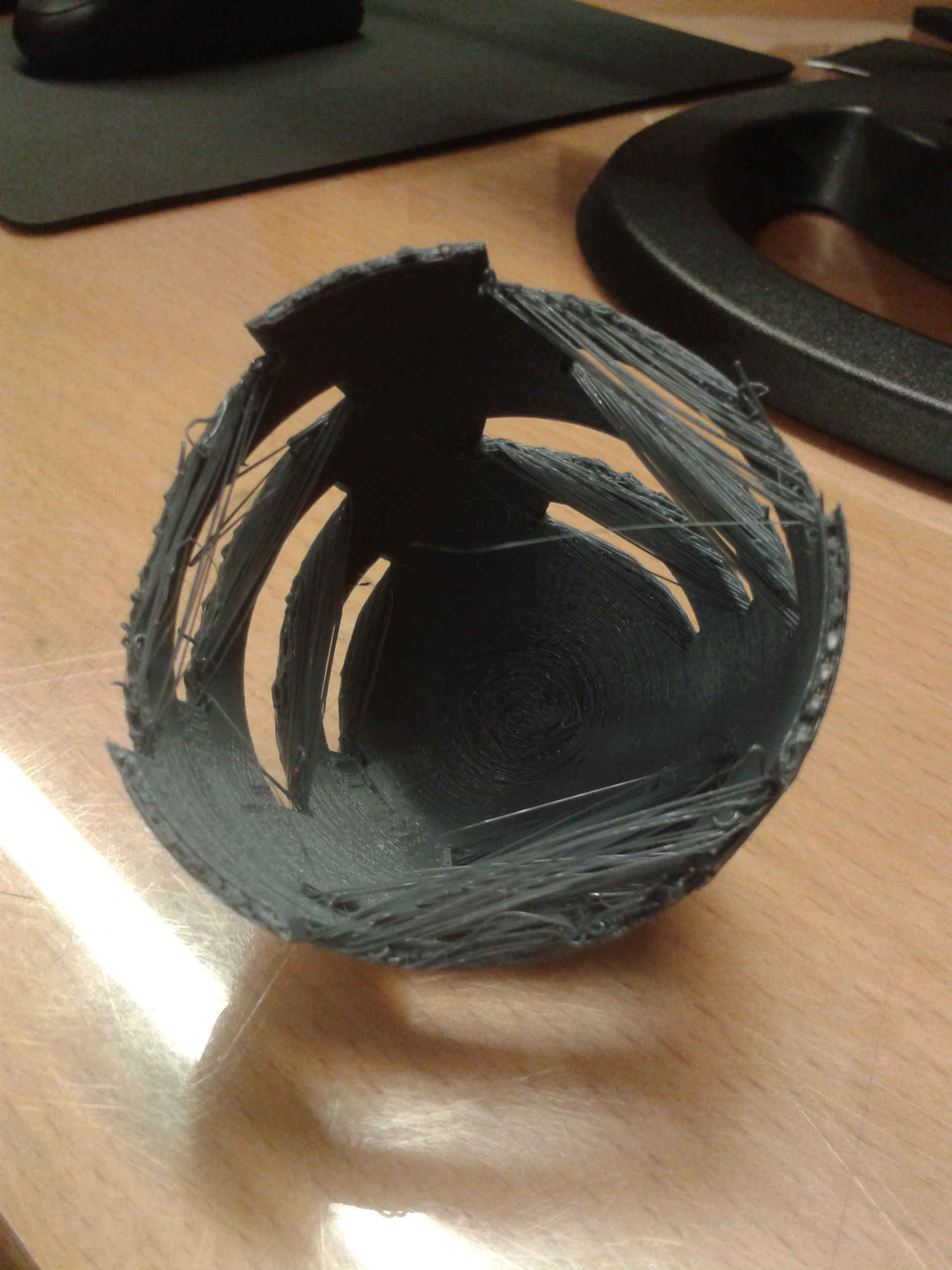
Only when the machine has created a sufficient number of layer upon wich it can put material, it starts to print a shape that looks curved. It sounds as if 3D printers use only little straight segments to create a shape that at the end looks like rounded. And if I had well understood this is what actually happens.
I can solve this problem by two ways: one is to reduce fissures width since the nozzle can print well between frames, as in the white globe; another is to insert supports in the fissures to temporary reduce the distance, and then remove them. The second one is certainly the best idea.
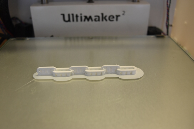
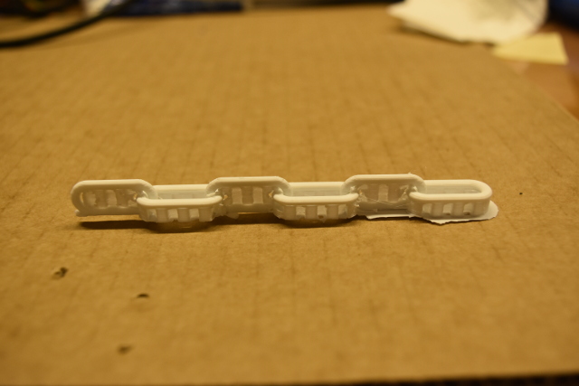
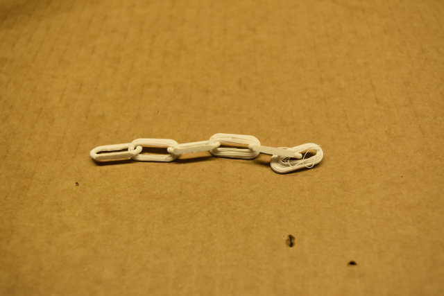
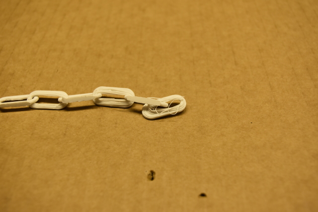
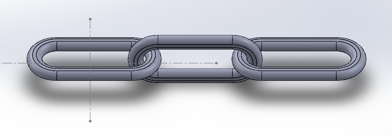
I also tried to print another shape that could not be made subtractively: a chain.
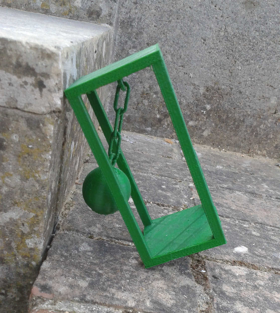
During this attempt I had another problems, this time with supports. In fact I printed the first prototype using not enough supports. In Cura you can select support placement between “touching buildplate” and “everywhere”. These are shots of the version I made using only touching buildplate supports.
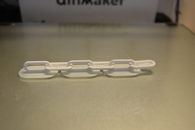
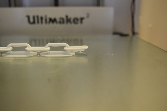
As you can see it gave me similar problems due to the lack of supports.
So I tried again...
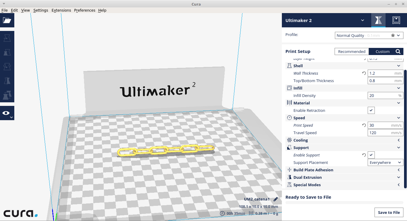
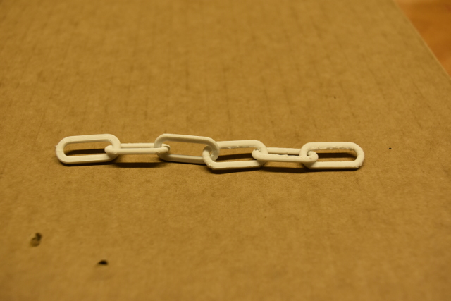
This is the new version of the printed chain I made using supports. This time I choose to place support everywhere because in my design some links of the chain are suspended, not touching the plate. This time I also used a new version of Cura.
Here you can compare the two version and clearly see the effects of right and wrong support placement.
Update
Despite all my attempts, during this week I wasn't able to make something acceptable, so I absolutely wanted to try again. Especially since I've learned lots of things due to my failures
So I modeled something else which could be made only by additive method
And then I've chosen appropriate settings on Cura
Here is the outcome
As you can see this time I wasn't mean with supports... XD
And the outcome was what I expected. So this time I consider myself satisfied
Hung Sphere by allarollonz on Sketchfab
3D Scanning
A 3D scanner is a device taht let you make a 3D model of a real object, which is modifiable and even 3D printed just like those made with a 3D modeling software
For the this part of the assignment I used Scan in a Box as the scanner, and its software IDEA to manage the job
I also followed thistutorial made by the productors to know how to use it
This scanner is composed of one projector and two cameras, and it works taking several pictures of an object from different point of view and putting them together to give back a 3D model
For my task I've chosen a small snowman shaped statue I've found around the lab

The first thing to do is to position the object in front of the cameras to put it completely framed and centered
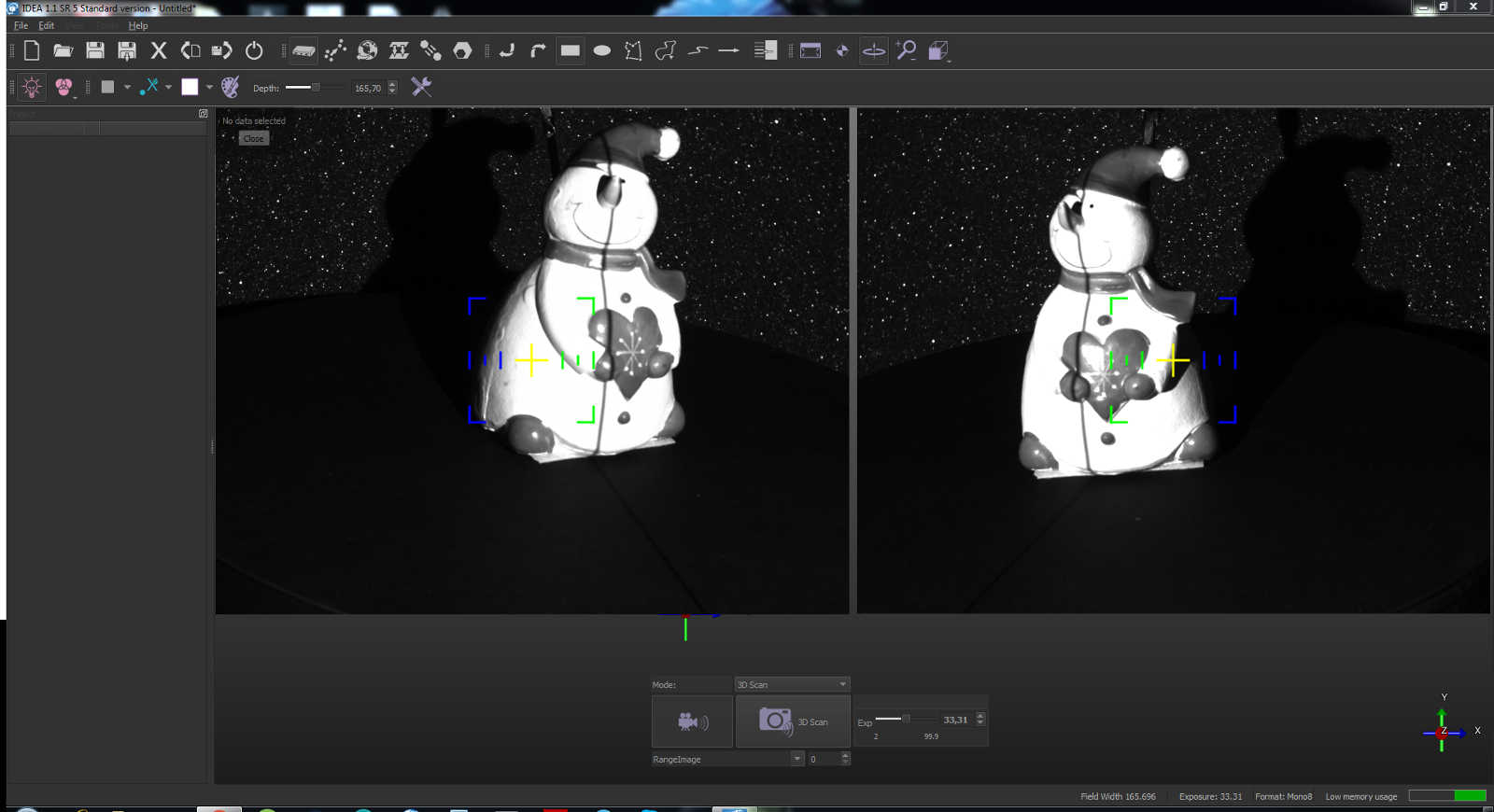
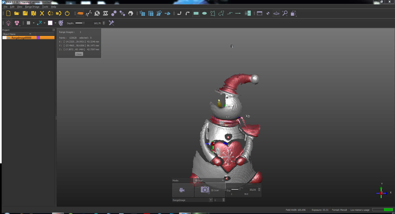
Now I could take the first 3D scan pushing the related button. In this way the first image appears in the left column, and I could see it in the main view
In there will be the list of all your scan shots. It's very important to put all the same perspective shots in a group because they get more easily menagable if they are grouped, to do this just right click on the image name and select "group"
Keeping the group selected any other shot you will take is going to be placed in that group
After any shot I had to rotate the real object to get another side shot. On the average, for the configuration we have set up it's enough to thake 14 shots to complete a 360 degrees rotation
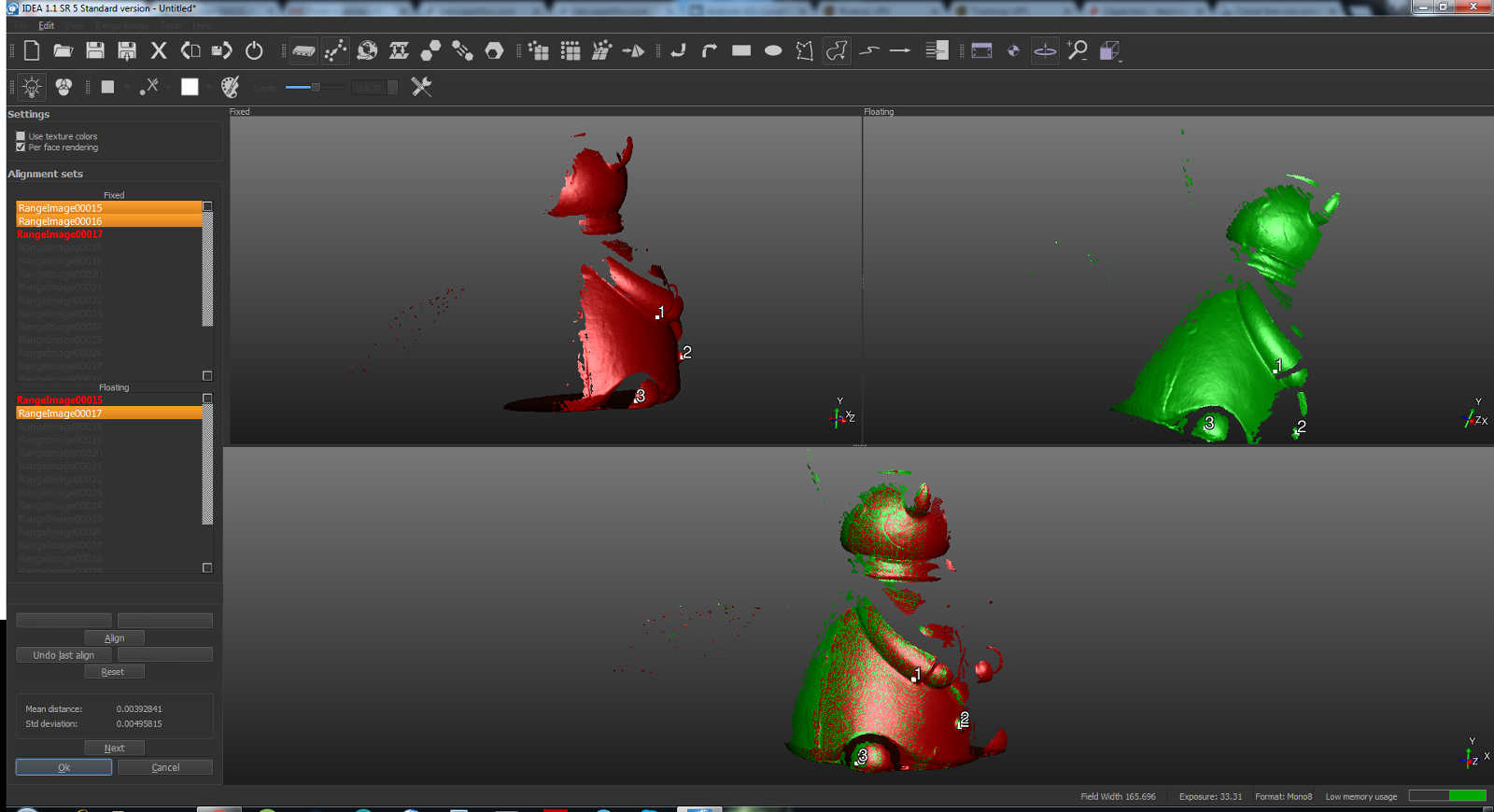
Once I've completed a turn, I could move to the "activate manual alignment" tool
Here, as you can see in the picture below, I had two lists on the left side panel. One is titled "fixed" and the other "floated". The first shot made has to be kept fixed and I moved to work in the floating list
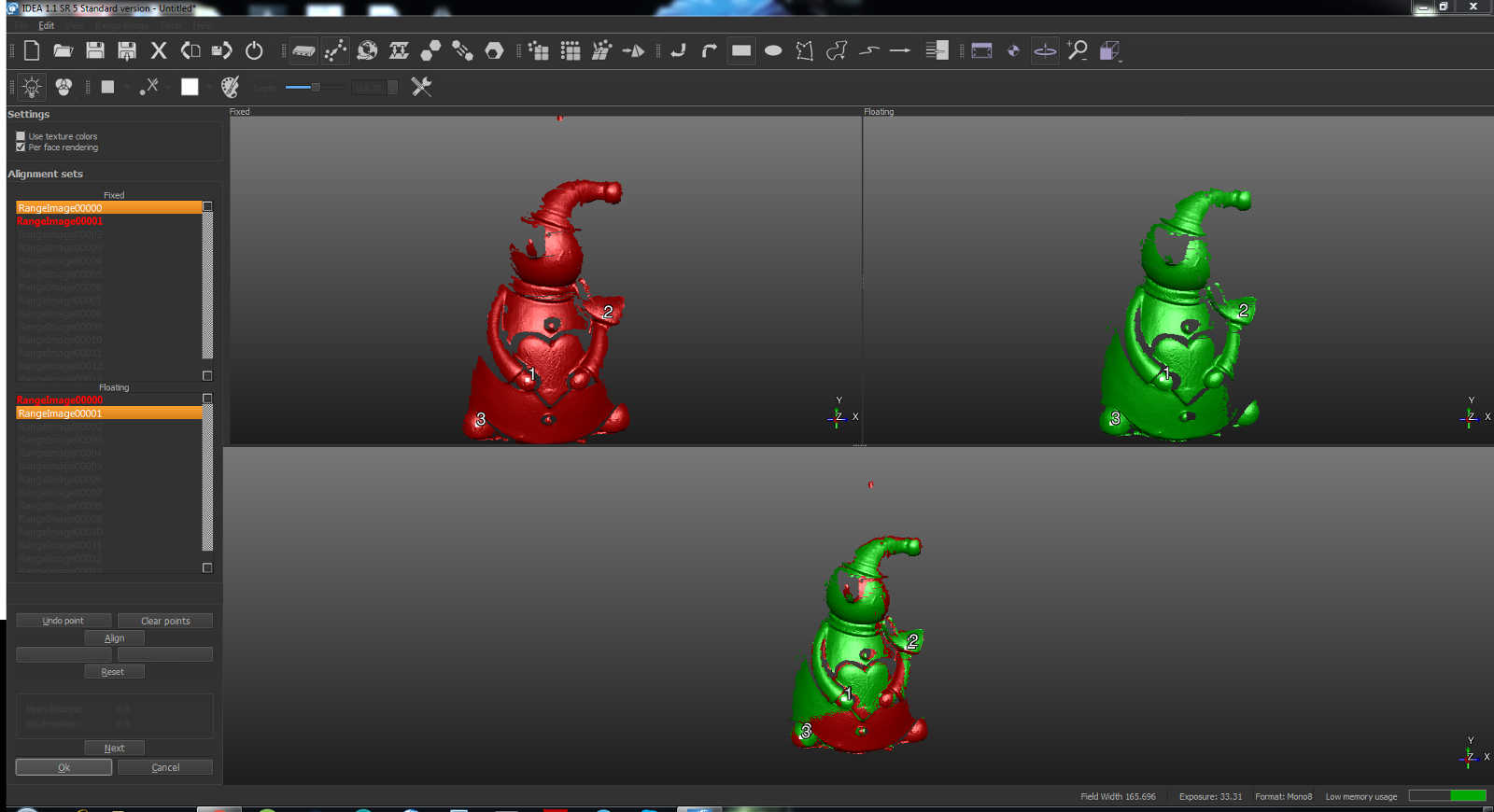
Now I had three views of the model, the left one is the fixed shot I have selected, the right one is the floating and the bottom one is the union of them
I had to select three common points in the left and the right viewport. Then I clicked on the "align" button below and I get the union
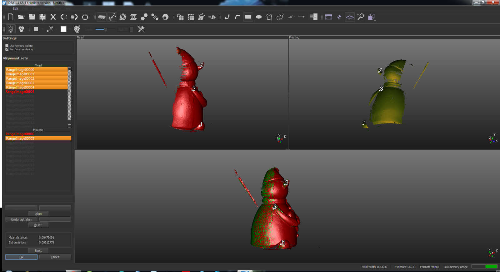
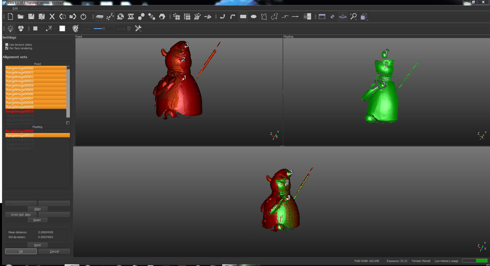
It's needed to repeat this operation for all the shot in the group
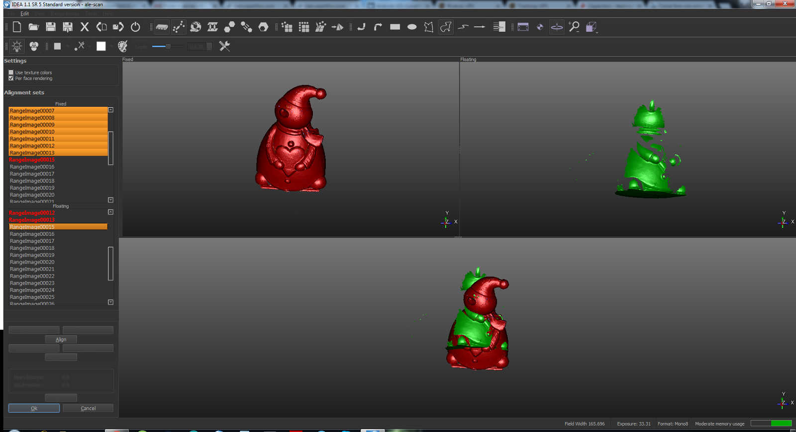
Now I inclined the model to get another side view and repeated all the same procedure. You need at least two perspective group of shots
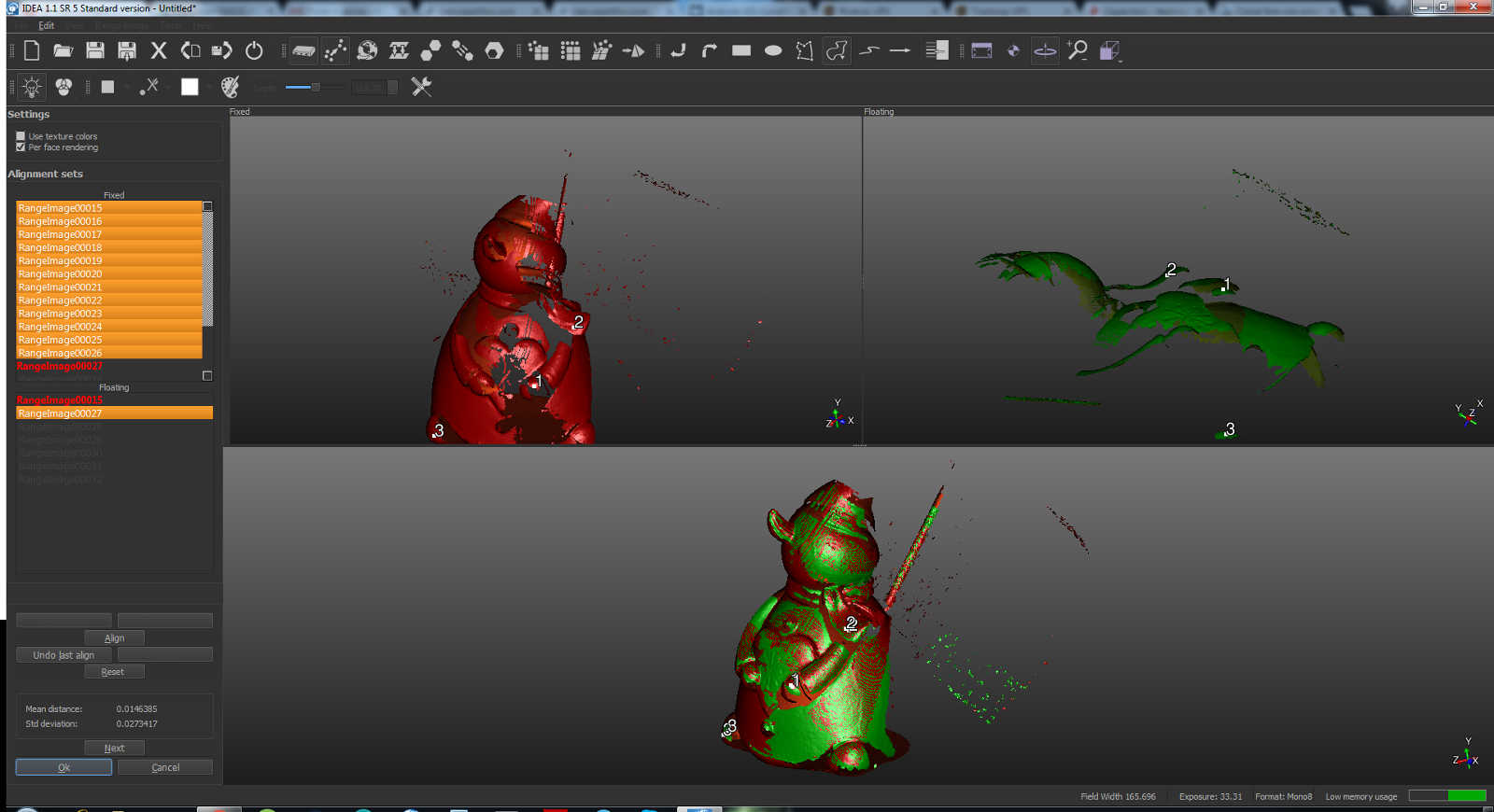
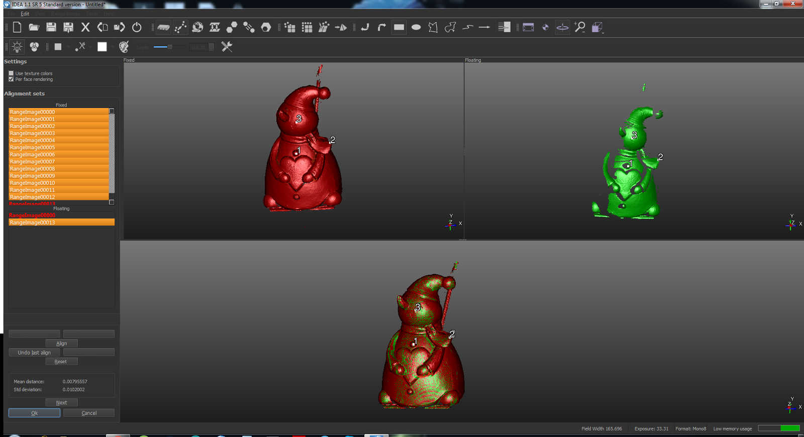
Now I selected all the scan in both the groups and then "activate manual alignment" againment. I kept fixed all the first group shots and floating those in the other group, aligning one by one all the second group shots with the whole first group
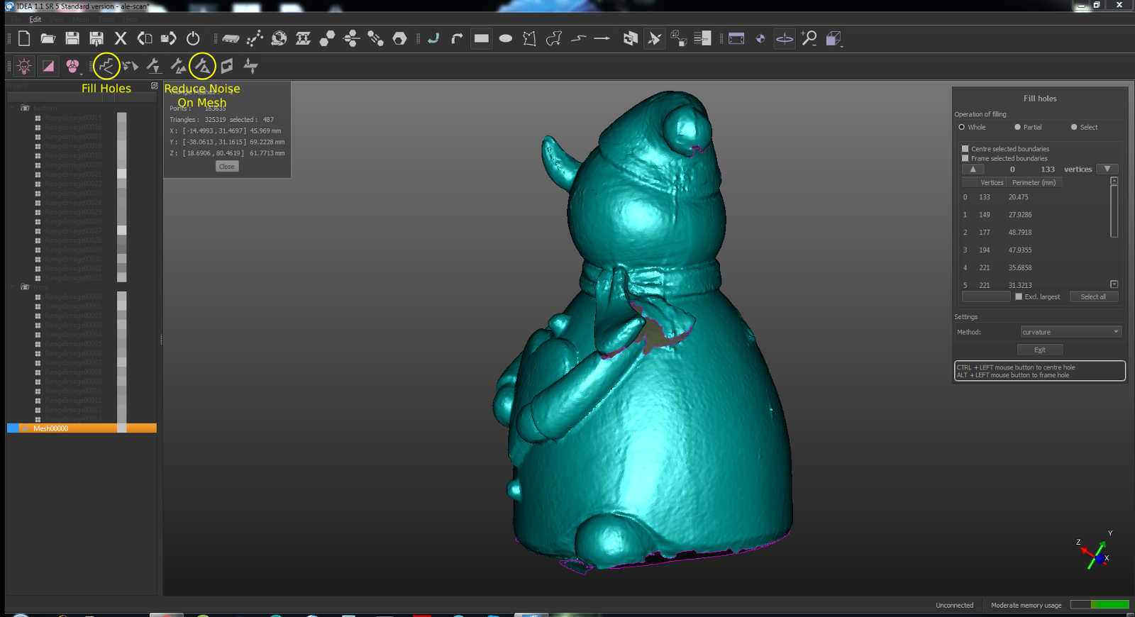
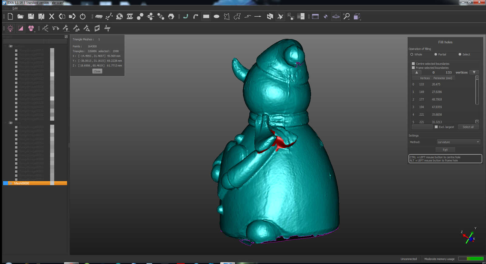
Now I moved to generate the mesh. It automatically create another group of mesh file. Keeping it selected I clicked on the "fill holes" button that let you fix missing portion of the mesh just by clicking on them
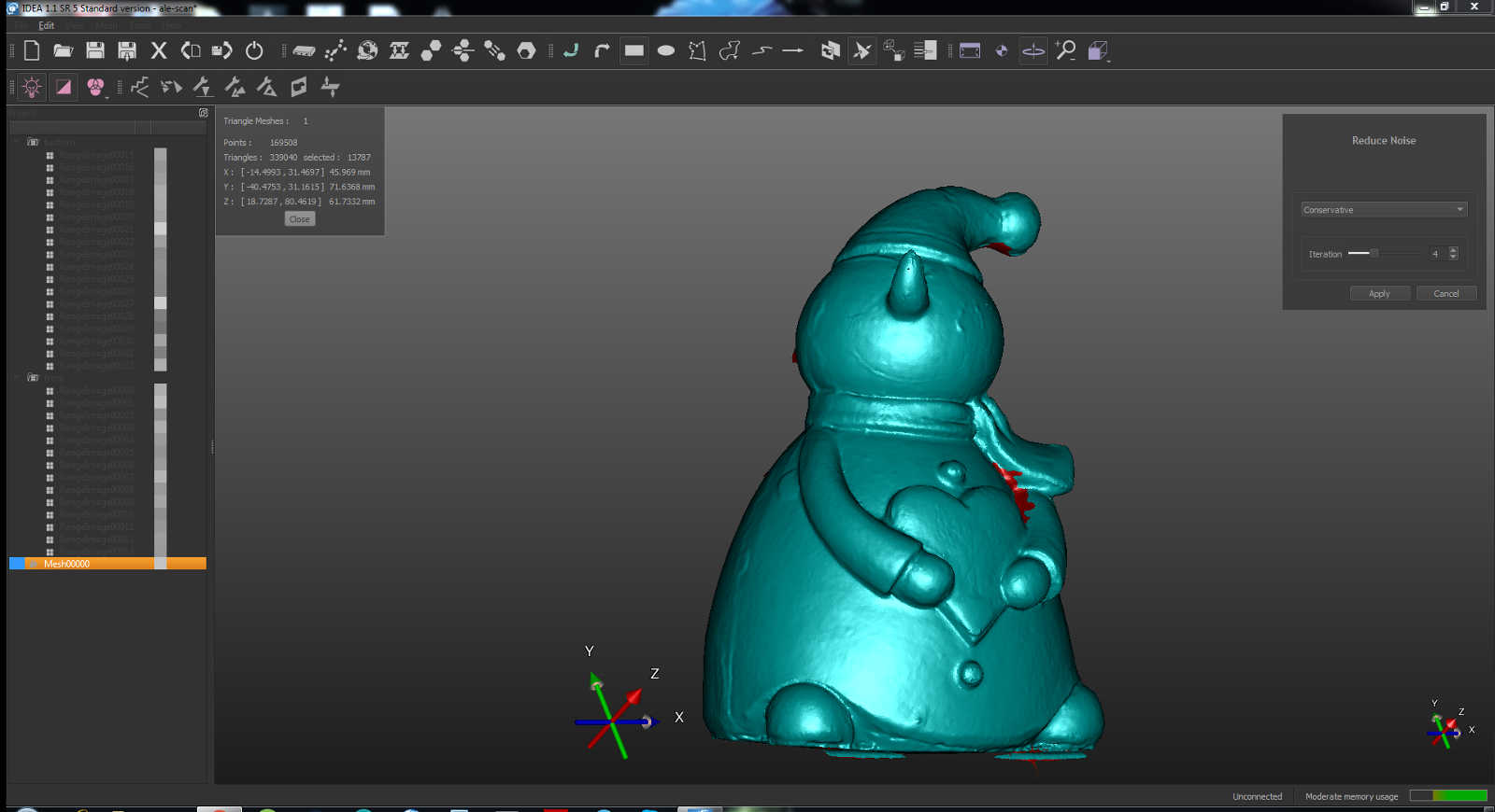
Then I tried the command "reduce noise on mesh" to see if it would become smoother, it really didn't make the difference in my case
Now everything have been done and I could export mi mesh as .stl file
You can view my original files here