
WEEK 4 – ELECTRONICS PRODUCTION
Weekly assignment
This week’s assignment was to make an in-circuit programmer by milling a printed circuit board (PCB).
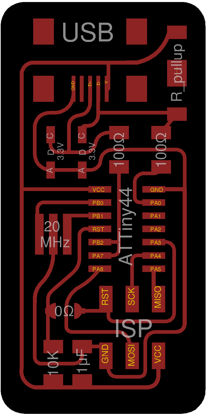
I've decided to make the FabOptimus, an optimized version of the Fab ISP made by Ali Shtarbanov. There are two version with 1.5K pull-up resistor and 1.0K+0.5K. I choose the second one because in our Lab we don’t have 1.5K resistors, so I had to combine a 1.0K and a 0.5K resistor.
Editing with Fab Modules
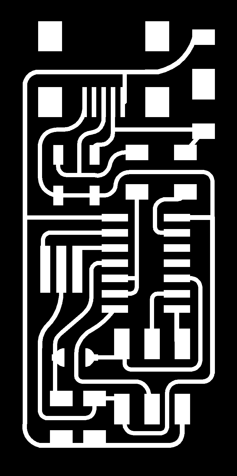
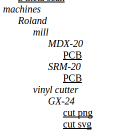
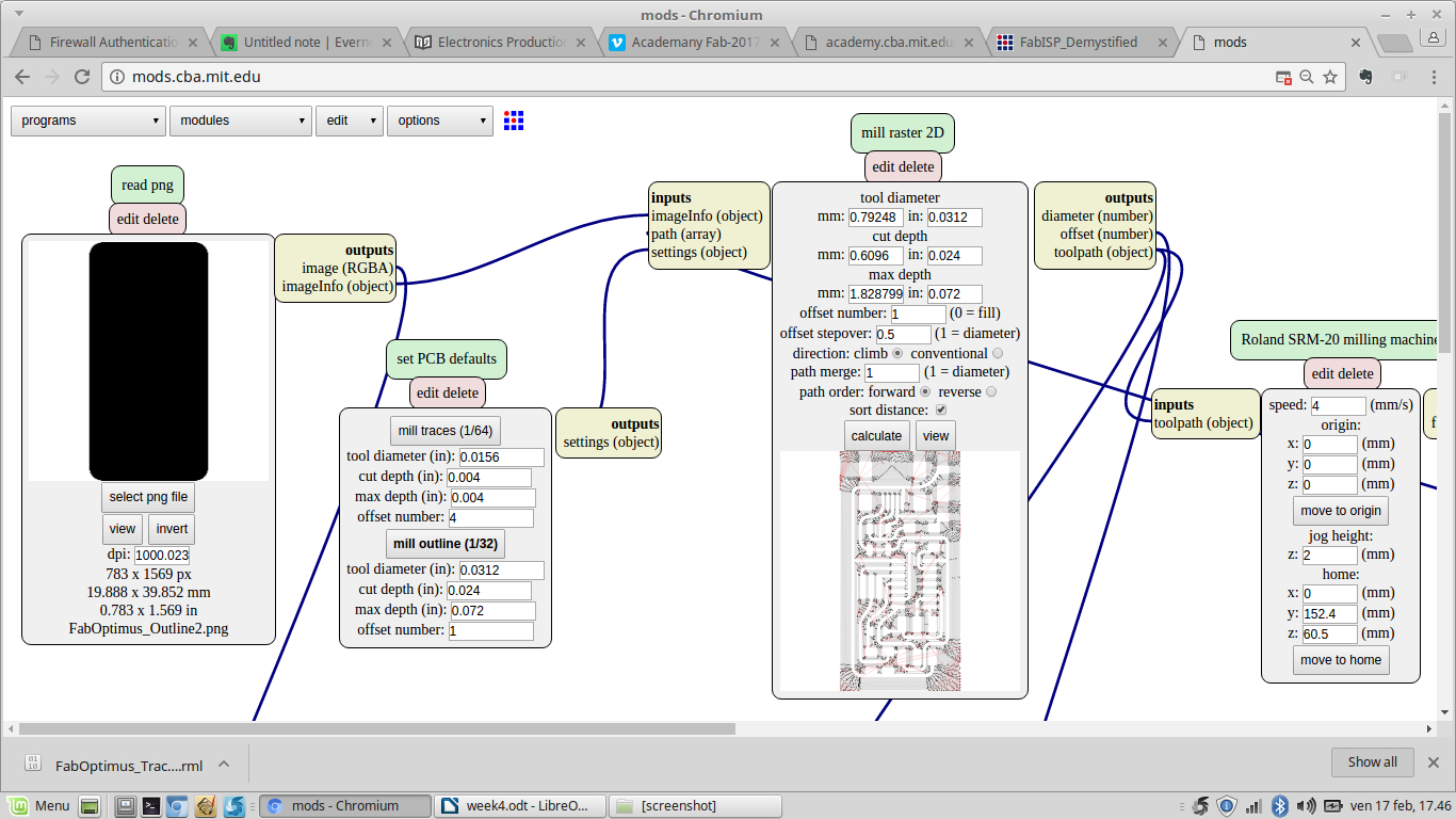
First of all I had to download the two png files with traces and outline.

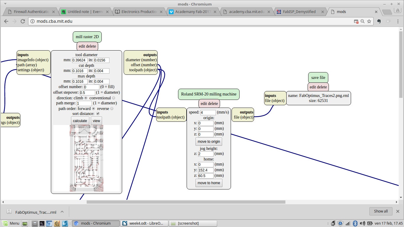
Then I created a file via Mods that I could use with the milling machine. To do this I opened a Roland mill SRM-20 PCB file
and I edited the mill traces file.
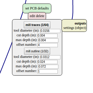
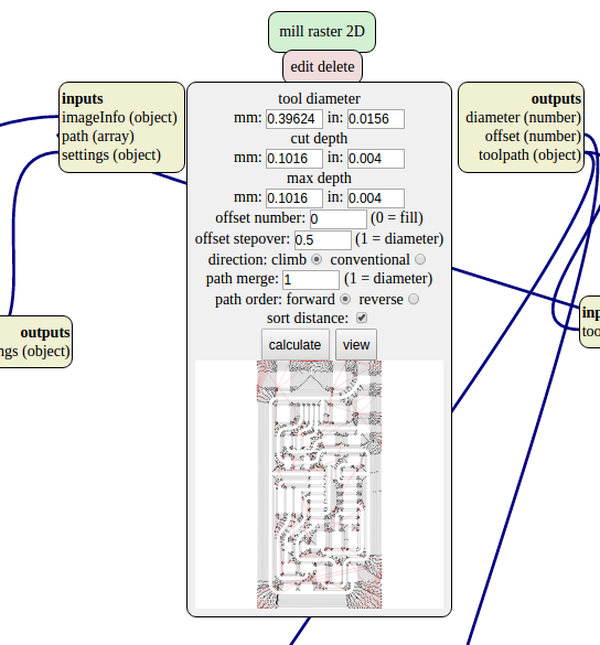
I also set the origin values at 0 and the jog height at 2 (this parameter refers to the z axis slide when the machine has to move the tip from a point to another without milling).
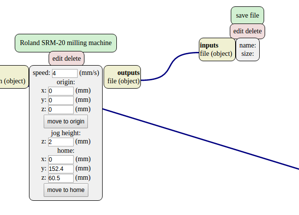
Now I moved to "modules-add server module" and I select "file-save". Then I linked this new module to "Roland SRM-20 milling machine", and I calculate the "mill raster 2D". So in the "save file" appears my .rml file.
Then I repeated the procedure for the outline
Milling with Roland SRM-20
To make my PCB I milled a single copper layer FR-1 board with a Roland SRM-20 using a 1/64 inch end mill for traces and a 1/32 inch end mill to cut the outline.
I started milling traces, but first I fixed the copper board to the machine plate with double-sided tape. This is important because if the board is not well fixed the end mill can move it while milling and break the tip.
So I moved to the VPanel for SRM-20 to position the end mill over the board and I set the X/Y origin point by clicking on the dark gray side of the panel. This is where the machine started to mill.
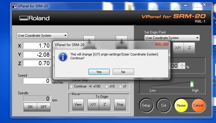
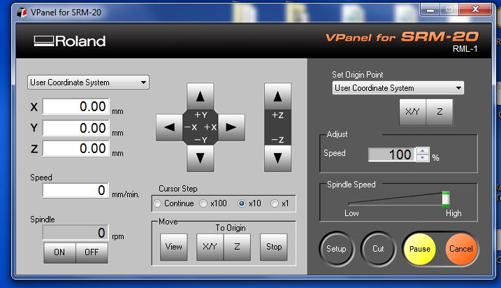
Then I positioned the Z and manually I unscrewed the 1/64 end mill to let it touch the board, paying attention to don’t break the very fragile tip. So I set the Z origin point. Now all the left side panel parameters are at 0.
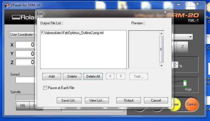
Then I clicked on the cut button and I added my .rml file.
For the outline I recalled the position from the light gray side of the panel, I repeated the procedure to change the end mill (now I used the 1/32) and I set the new position as Z origin point. Then I added the file and cutted.
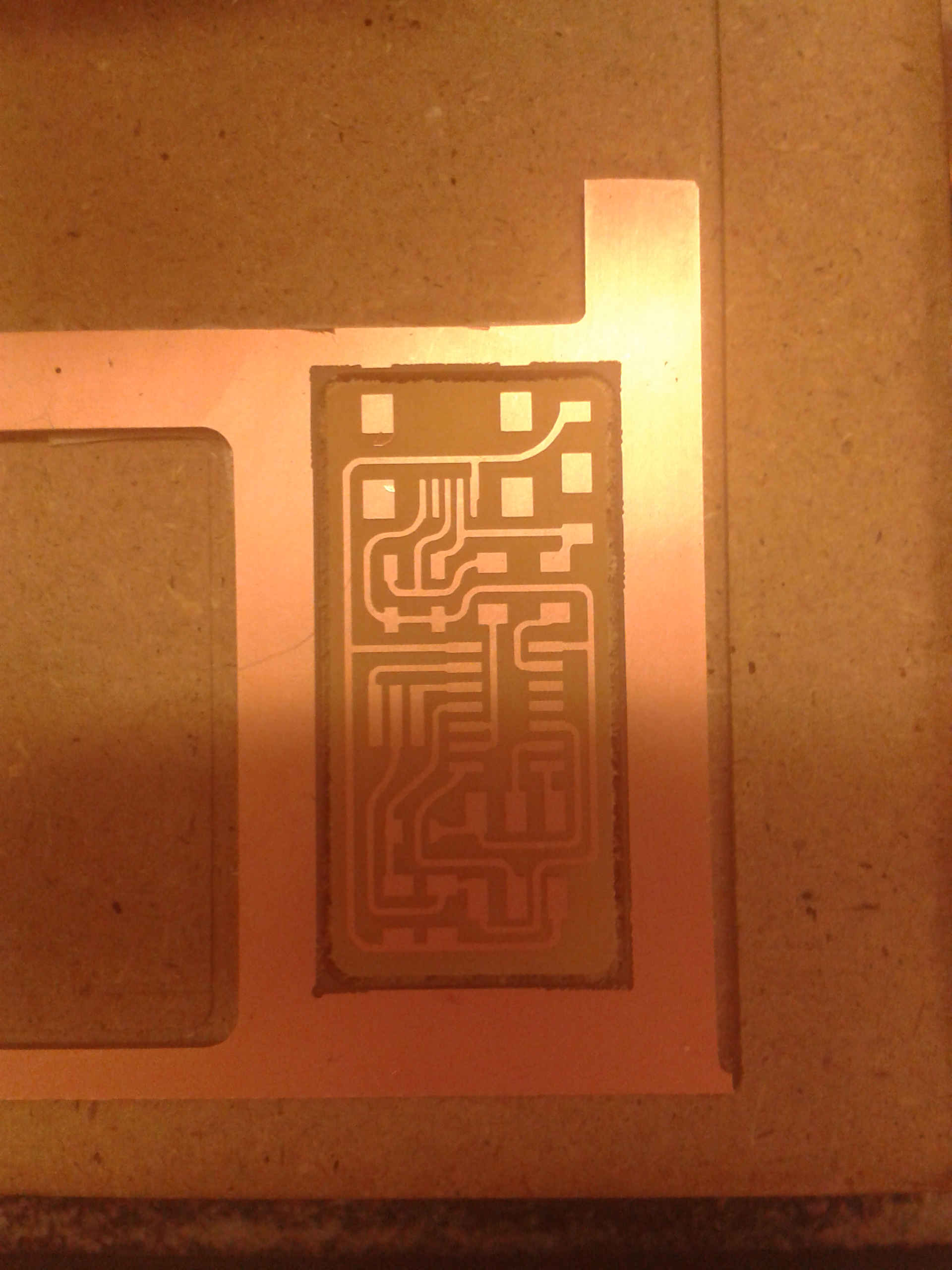
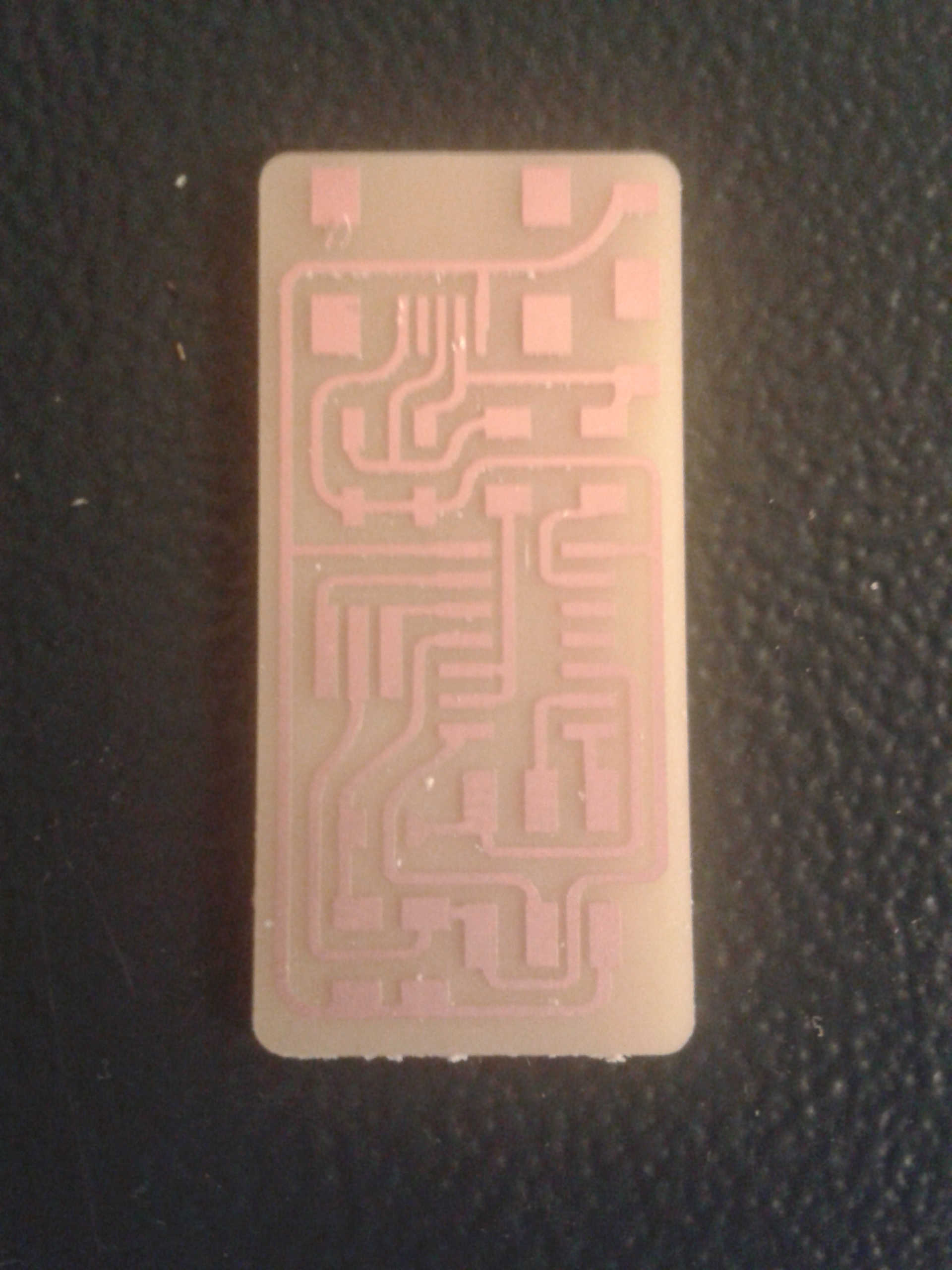
This is what I gained.
Assembling the FabISP
Now I was ready to solder. To do this step I started making a BOM, so I made a list of all the components I needed ordinating them in column on a paper writing the correspondent name. Then I started to solder.
It was the first time for me and at the beginning I was a bit scared because the components and the copper traces looked too small! But fighting against the hand shaking I soldered my first component, the ATTiny44. To be sure everything went fine I made soon a test with the voltmeter and I found my solders seem to work. So I continued more relaxed.
When all the components were soldered I made another global test with the voltmeter, and everything seems to work as well.
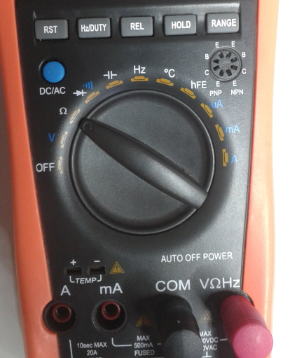
This is the voltmeter setup to test the resistors, if everything works you should see the related values.
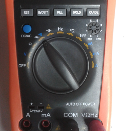
And this is the setup for the others, if there is a connection the tool makes a sound.
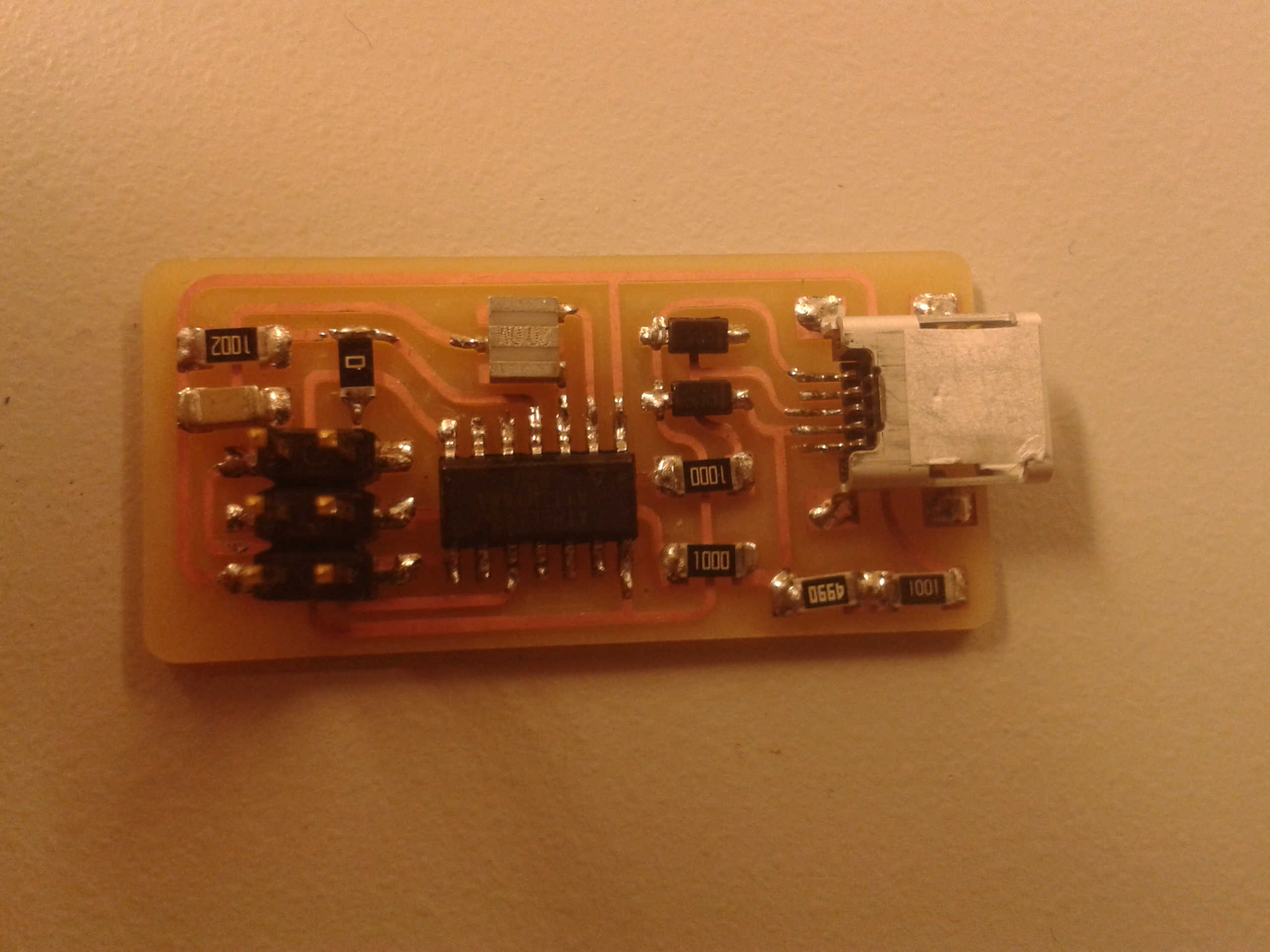
This is my FabISP
Programming the FabISP
To program my FabISP I followed Anna Kaziunas France's tutorial on the Fab Academy archive.
So I installed avrdude and GCC software. Then I downloaded the firmware and unzipped it. To program my board I used another working FabISP we have in our Lab and so, as specified in the tutorial, I edited the Makefile.
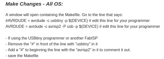
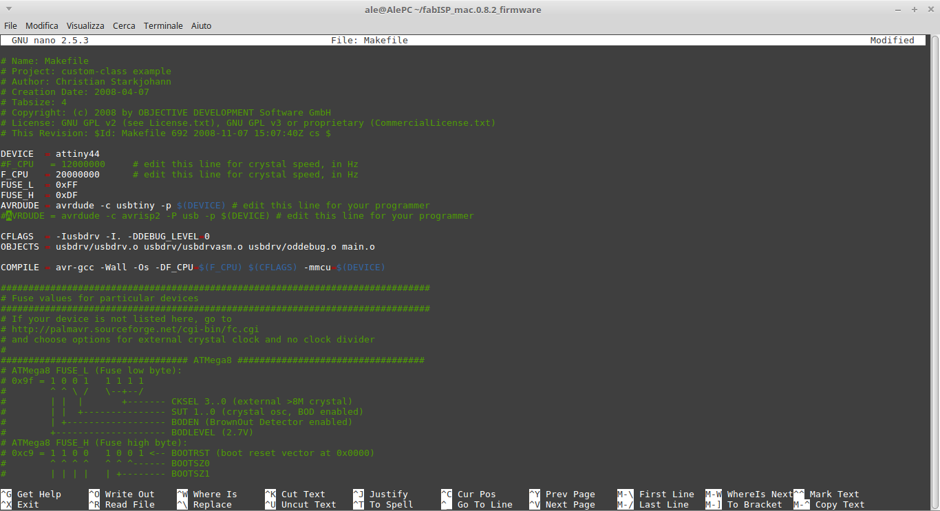
Before to actually program my FabIsp I needed to compile the firmware and to set the fuses, so I could program...
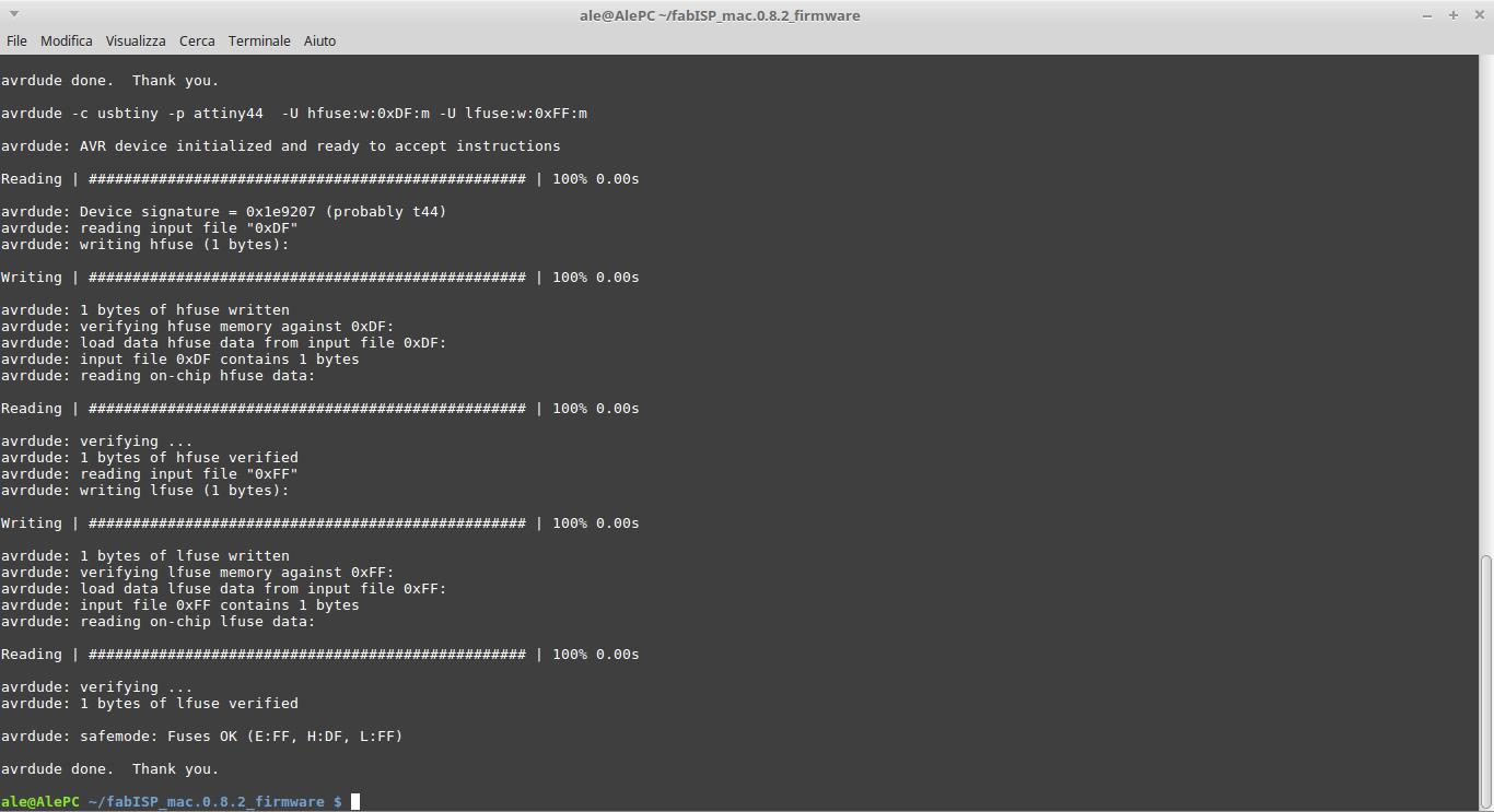
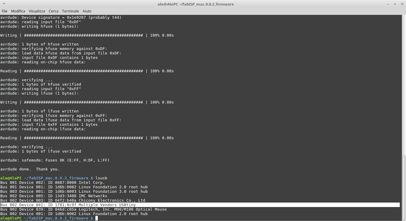
To be sure that everything went fine I searched the FabISP among the USB devices in my computer.
You can find the milling traces file here