8th Week, Embedded programming
This week we focused on embedded programming. The assignment was to read the 300 pages data sheet of the atTiny, and then program the Hello Echo board which we created during the 6th week.
Reading the atTiny data sheet
Before opening the data sheet of the atTiny, I looked at its contents, and decided to do some pre-reading in order to understand the basic concepts. Here are the most useful websites I visited.
microcontroller basics (very helpful for beginners like me!)
transistors
integrated circuits
how the cpu works
Pull up resistors
Interrupts
Watchdog timer
Registers
Timers/counters
how to read a microcontroller data sheet
I then decided it was time to dive into the actual data sheet. What I did was try to understand what each section is about, and what its basic characteristics are. The most interesting parts were those that I could understand so I am listing them below as I understood them.
Pin configurations and descriptions
This section explains what each one of the 14 pins of the atTiny 44 does. There is a VCC, a Ground, a Reset and two groups of I/O ports the group A and the goup B which serve as input and outputs, but can also have various other functions.

More information about the I/O ports can be found in the relevant chapter (no 10), where one can also see the schematic of a general I/O port, how it configured so as to be able to be both input and Output, and how it communicates with the 8 bit Data Bus.

CPU core
The CPU is the “brains” of the microcontroller. Here one can find the overview diagram of the AVR architecture used in the atTiny which shows the basic components of the CPU. AVR is the family of the microcontroller, developed by Atmel, which is a modified Harvard architecture 8-bit RISC single-chip, using on-chip flash memory.

Memory
In this section, the different types of memory inside the microcontroller are explained. First comes the In-system reprogrammable flash memory for program storage. Another memory is the “SRAM Data memory”, divided in Register file, I/O memory and internal SRAM, the EEPROM Data memory , and the I/O Memory
Clock system
The microcontroller has an internal clock which consists of 4 different sub-clocks: one for the CPU, one for the I/O, one for the flash memory, and one for the ADC conversion. Another interesting component here is the watchdog timer, which is responsible for checking if the microcontroller works as expected, and if not, it restarts it. An external clock can also be connected to increase the accuracy of the time counting.
Analog to Digital Converter
This section explains how analog is converted to digital, and how this process is connected with the clock. It also explains what mechanisms are used for reduction of noise, and what the bits of the relevant registers represent.
Memory Programming
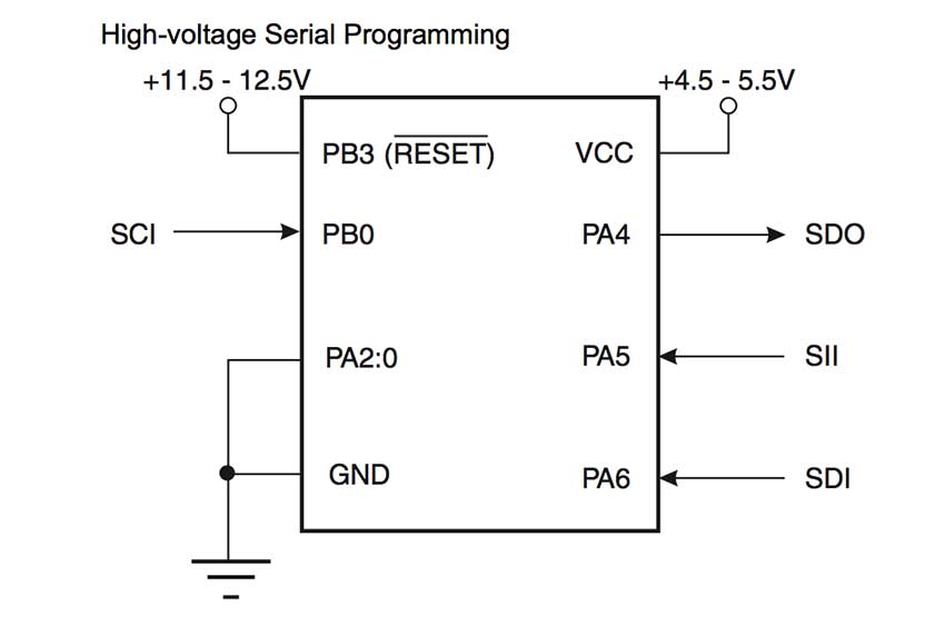
Here is all the information about how to store a program in the memory of the atTiny. Firstly the fuses are explained, three bytes in the microcontroller which are saved to control its behaviour concerning its “vital” actions. Similar to the fuses is the Device Signature Imprint Table , a memory dedicated for storing miscellaneous device information, such as oscillator calibration data. Then comes the part of the memory that can be used to store a program, with high-voltage serial programming.
Electrical Characteristics
In this section the minimum and maximum values of voltage and current are explained. Using the microcontroller within those limits guarantees that its behaviour and life span will be as described in the data sheet.
Programming the HelloEcho board
Programming with Arduino IDE
With all this information in mind, and help from this tutorial about programming the atTiny with Arduino from the fab Academy website, I tried to program my HelloEcho board, which I had produced during the 6th Week.
However, despite doing everything correctly I always got an error from the computer.
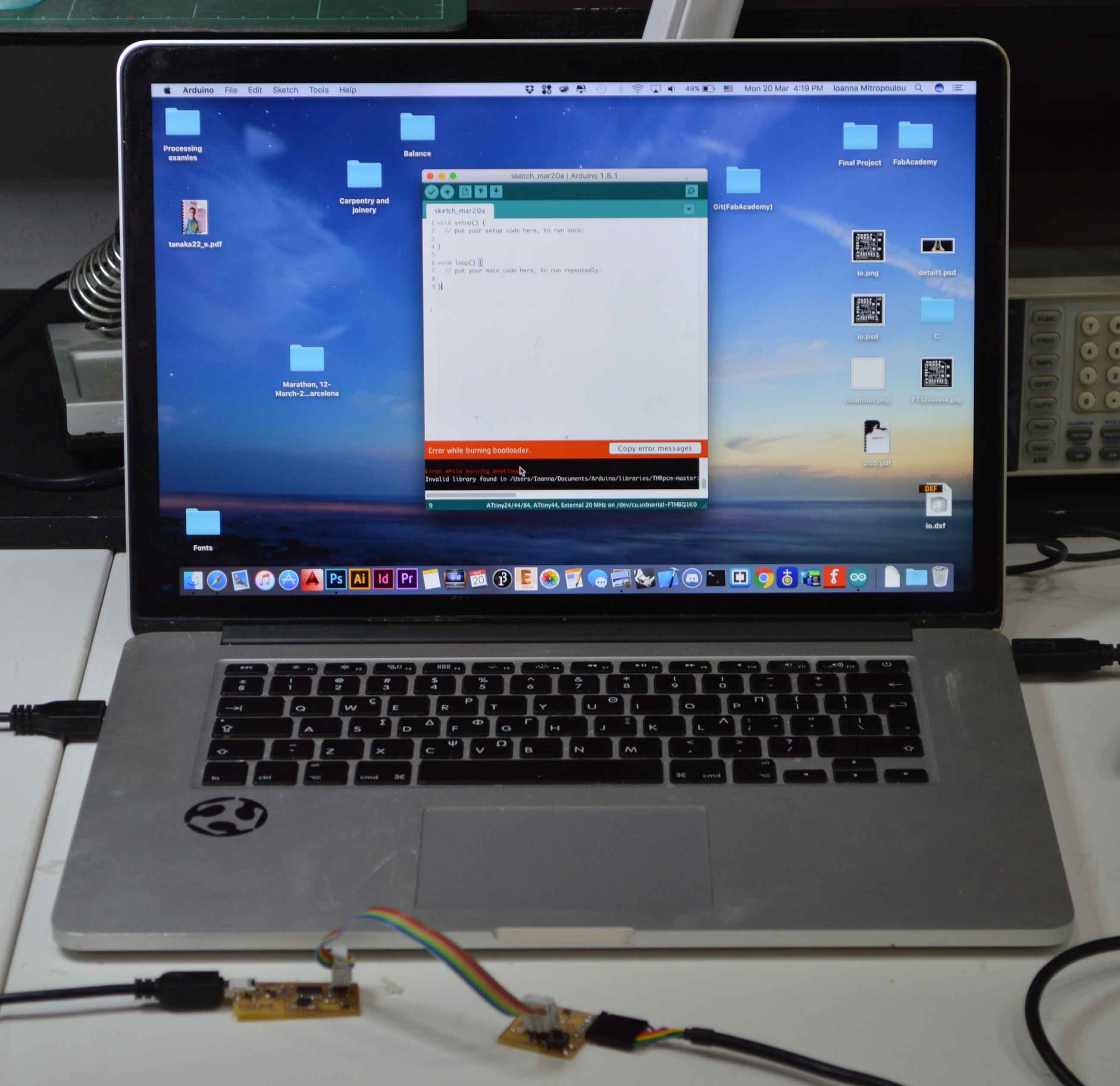
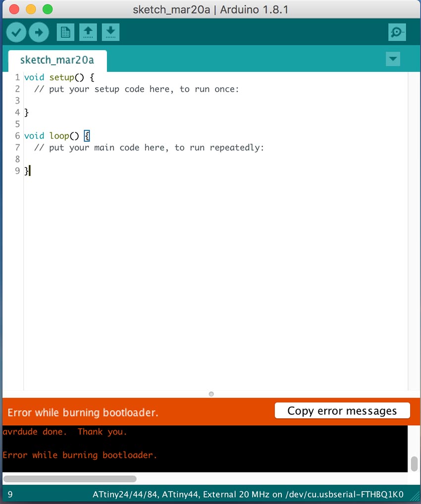
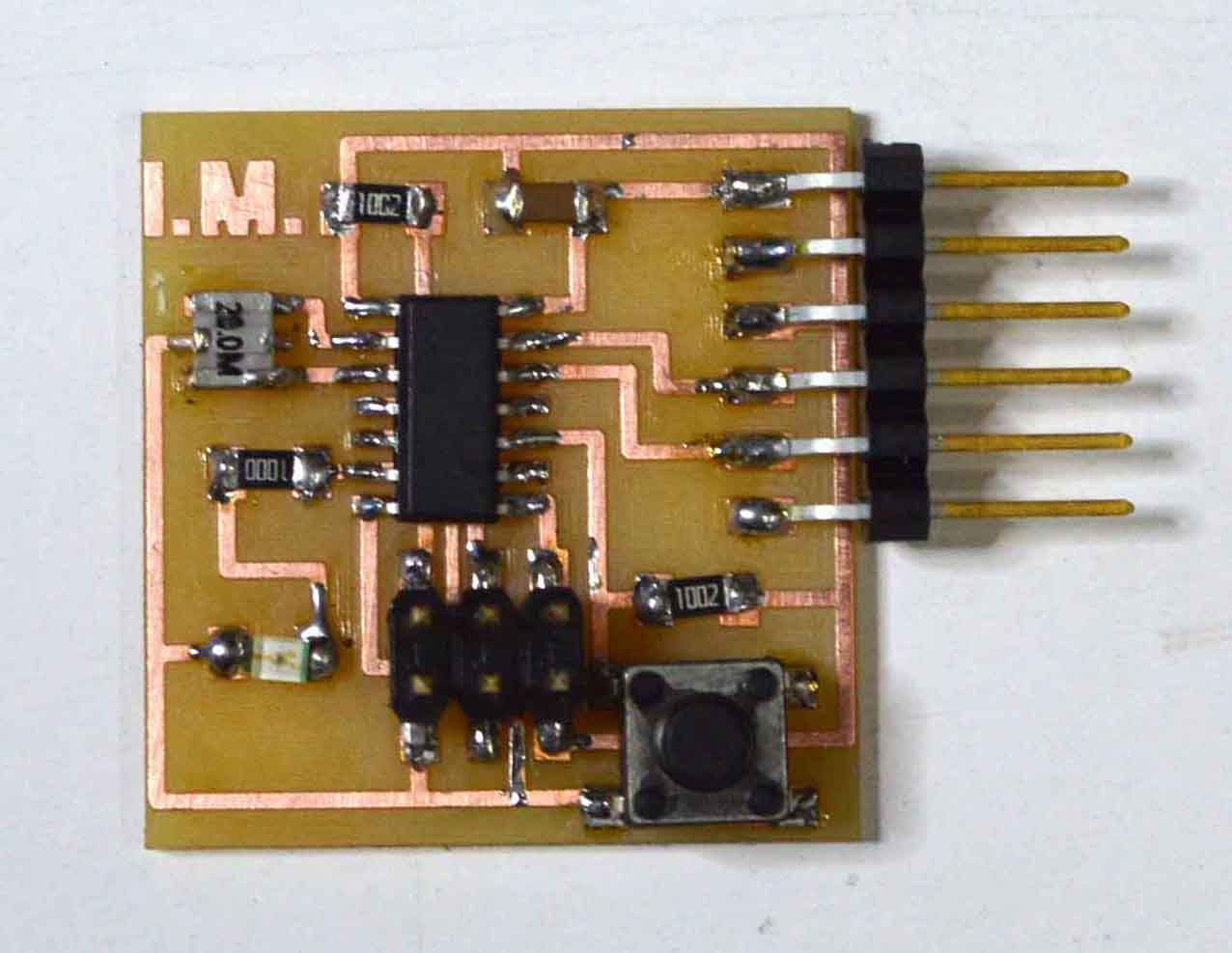
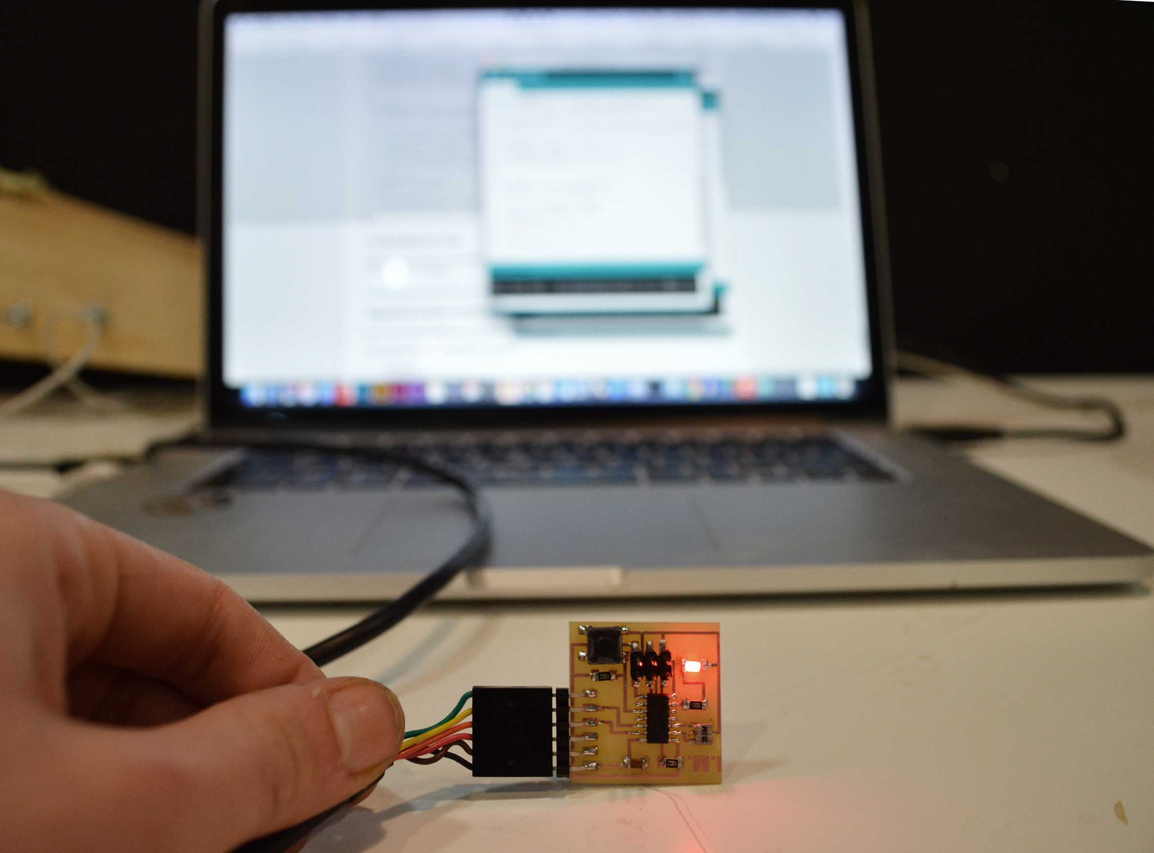
To narrow down the problem, I tried to program another HelloEcho in my computer, and it worked perfectly, so the problem was in the board. With help from the multimeter I found out that one of the atTiny’s pins was not connected as it should be. In an effort to fix that, I destroyed my atTiny. A few hours later, and after a series of similar bad interventions on the board I decided I should re-do it from scratch, saving as many components as possible from the old one. And so it happened. Here’s my brand new HelloEcho board with which I completed this week’s assignment.
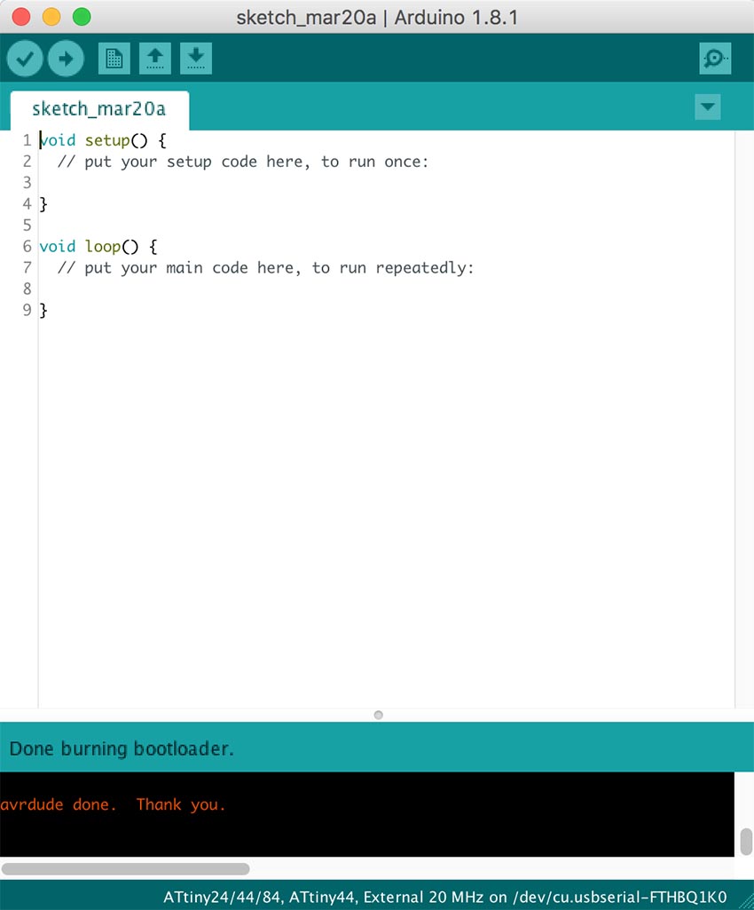
After this adventure, everything went as expected. Here are the necessary settings on the Arduino IDE to be able to program the atTiny with the fabISP.

The board must be connected to the ISP and the ISP to the computer, and to power with the FTDI header, in other words, two USB ports are necessary for this process. I burnt the bootloader, and uploaded the first Arduino sketch which turns on and off the LED depending on the input from the button.
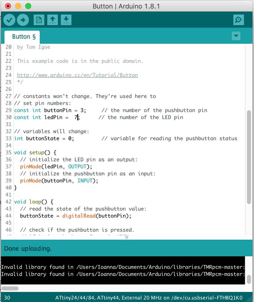
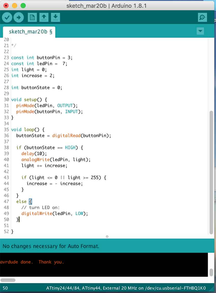
I then experimented with changing the code, and so I made the light blink when the button is pushed
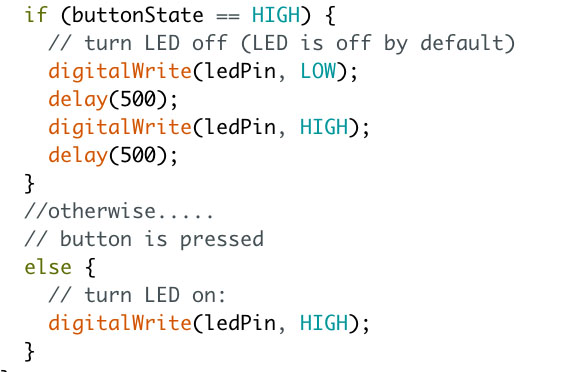
and also fade in and fade out.
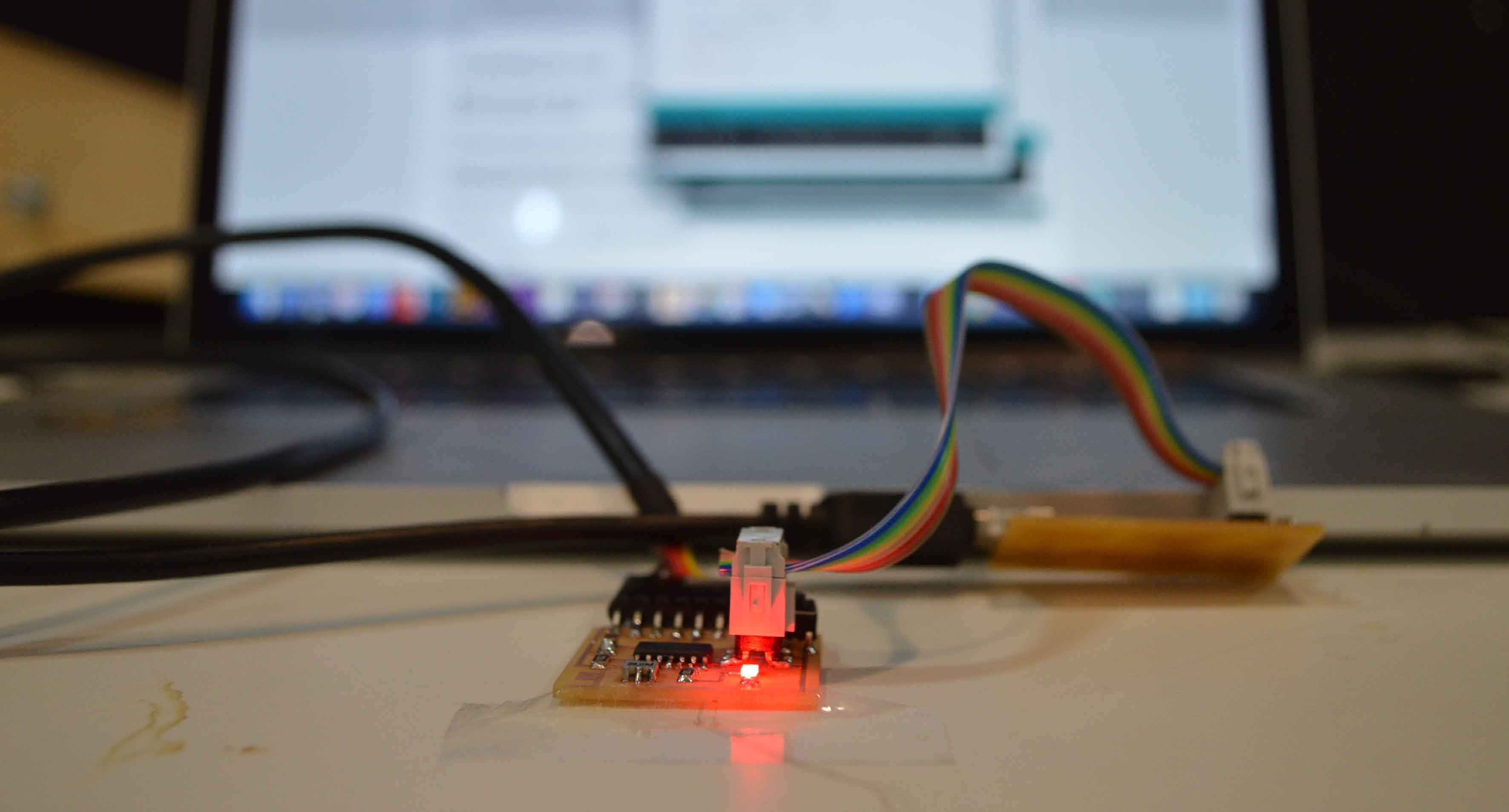
After the board has been programmed, the connection with the fabISP can be removed, and the only thing needed for the board to function is power from the FTDI cable.
Here you can download the arduino code: blink, button
Programming with C
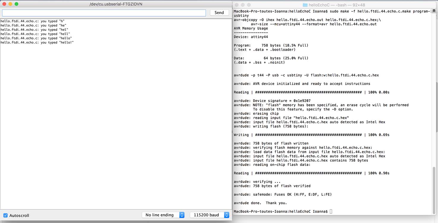
The same connections (board to fabISP and FTDI cable) are necessary for programming the pcb using C. For the task I used this tutorial on programming the Hello Echo board using C, again from the fab Academy website.