2nd Week, computer-aided design
The second week was about computer aided design. Being in an architecture school for the past 5 years, I have a lot of experience with 2D and 3D designing tools. Softwares such as AutoCAD 2D, Photoshop, and Illustrator were used on a daily basis. I also used 3DS Max and the VRay rendering engine for renders, as well as Rhino and grasshopper for 3D modelling and parametric design, or just experimentation.
For this exercise I want to focus on parametric design. That is why I will not use a lot of 2D or 2.5D design tools as I already feel comfortable with them, nor will I spend time on rendering engines to produce nice graphics.
My goal is to make mechanisms that could be used for my final project, and, if possible, animate them to see how they work. The options I considered where Rhino and Grasshopper, with which I am already familiar, as well as Inventor, Antimony and SolidWorks, which I just started learning this week. My work on the new tools was experimental and I couldn’t achieve the results I wanted, so I’m only presenting what I did on Grasshopper because it is more complete, and I will include a few screenshots from the other softwares.
After a research I’ve been doing for a few weeks now I’ve found a few mechanisms that I believe have a potential for an architectural project. I tried to work on as many as possible so as to explore a lot of options, but only two of them were complete. During this process many ideas arised which I describe below.
Expandable surfaces
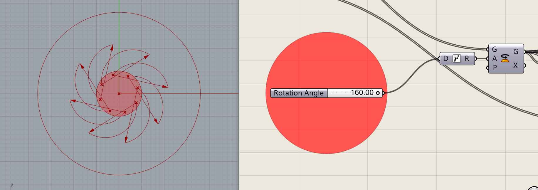
My first experimentation was inspired by the mechanism of expandable tables. The basic idea is that by employing metallic pieces with curved profiles attached to a central piece and with a rotary movement, expansion of surfaces can be achieved.
To model this I used Grasshopper. I started from a circle that expands into a bigger circle, as most of my references provided information on that, but since the model is parametric, the concept can be expanded to a variety of shapes and sizes.
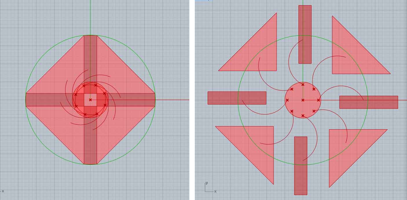
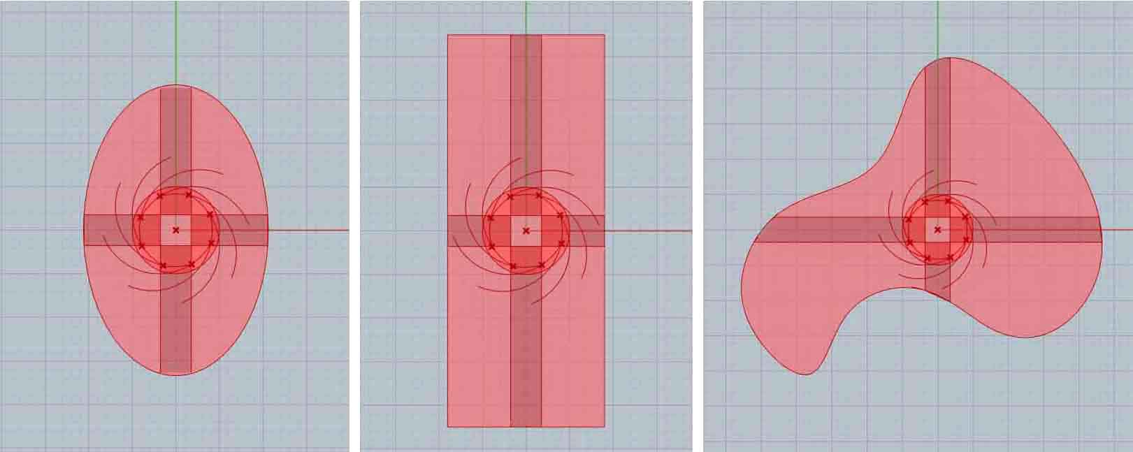
This idea could be applied to architecture in many ways. One way is, as it is shown on my expanding-table reference, to use it to design furniture or objects of daily use so that they can expand and shrink, thus serving more purposes than a static object. Another idea that interests me more for my final project is to use it on a responsive facade of a building which can adjust its shape according to the conditions of the environment, the wishes of the user, or any other input.
Expanding Surface, Grasshopper from Ioanna Mitropoulou on Vimeo.
You can download the Grasshopper file here.
Note #1: I couldn’t compress the video file enough to be able to put it in the GIT repository, so I uploaded it on Vimeo and embedded it on this website.
References:
Expanding Table Kit: Prototype
How the Fletcher Capstan Table is Made
Counterweights
Using counterweights for moving parts is a very simple yet really powerful concept that is often used when there is need for very smooth movement or for moving heavy parts without requiring a lot of strength. The basic idea is that it is much easier to move one element if you can provide a counterweight through a smart geometrical configuration or by using elements such as levers or ropes. The main disadvantage of this strategy is that it almost doubles the weight of the assembly.
This mechanism has also a lot of applications in architecture both on its own and combined with other mechanisms. It is very efficient for moving platforms, surfaces and heavy objects. The application that interests me for the final project is inspired by a moving arm for a camera, the link to which I provide on my references below. I believe that this mechanism could be used for an opening roof, so this is what I tried to model here.
Counterweights from Ioanna Mitropoulou on Vimeo.

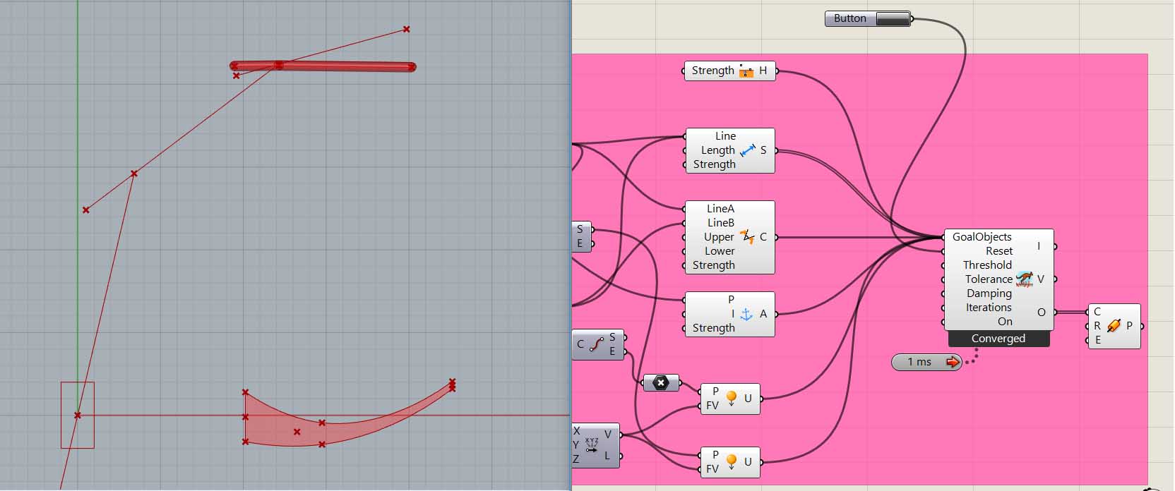
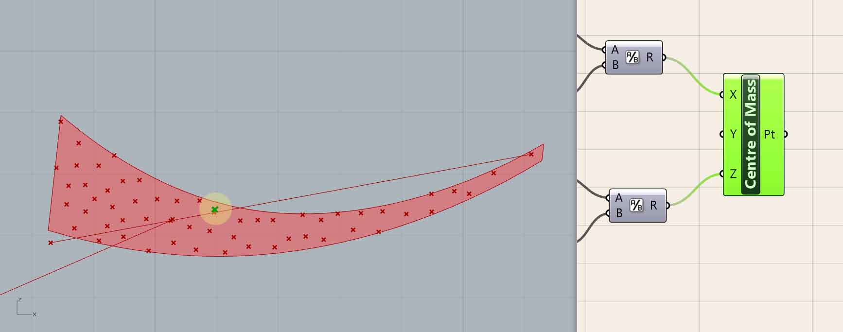
I started once again using Grasshopper, mostly because of its plugin, Kangaroo, a physics engine, very useful for simulations. I have used Kangaroo before, usually with success, but here I soon ran into problems. I will not go into details about this, but overall, it didn’t seem to calculate correctly forces that are applied to objects anchored on one pivot point different from their “centre of mass”. In the picture you can see the problem. The object has two forces of the same size in both its ends, yet it balances in that position. It only takes Newton’s physics laws, or some common sense to figure out that this is wrong. It was not equally easy to correct it though.
After giving up on Kangaroo, I decided I still needed at least a way to roughly calculate the centre of mass of the elements. Since I’m working in two dimensions, what I did was populate the surface of the element with random points, and average those points. I’m sure there must be many easier and more efficient ways to do this, but sometimes reinventing the wheel feels good.
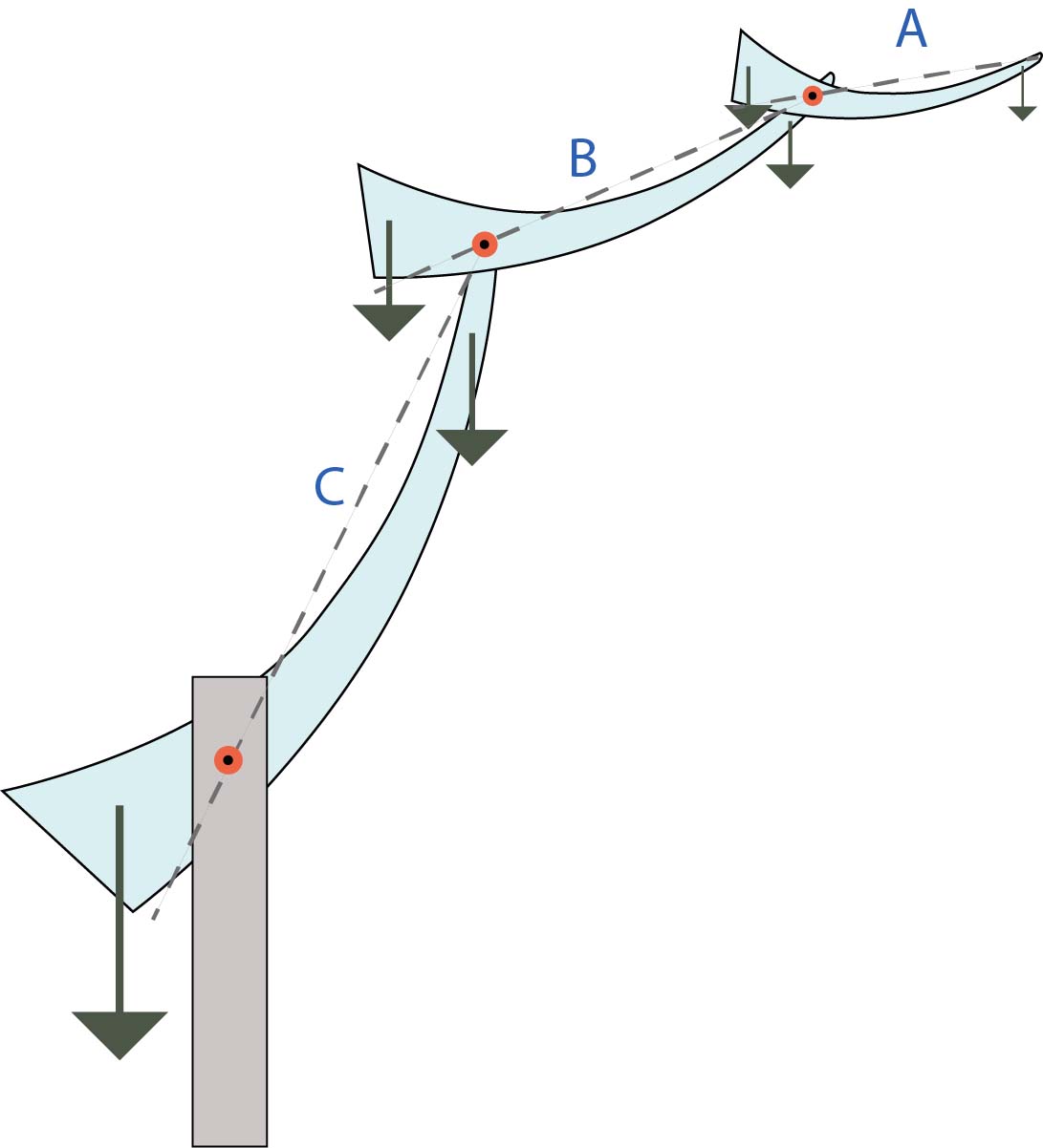
This is nothing but a rough sketch of what this opening roof could look like. The idea is that if the elements are designed so that their centre of mass is the same as their pivot point, then the whole roof could be balanced and easy to move. This could be achieved both by geometry (the element is thicker on the left), and by having non-uniform density, for example filling with sand the left part of the element. Here it is not designed as such, but this is the direction this sketch should go to if I continue working on it.

Of course this means that the counterweight of each element has to be heavy enough to compensate for its own weight and the weight of all the elements above it. As a result, the counterweight of the element closer to the base has to be more or less equal to the weight of the whole roof.
What is more, the flexibility of the roof is not always a good thing, which is why all elements should have a locking mechanism that holds them in place when movement is not desirable.
You can download the Grasshopper file here.
References:
Camera Control Arm
Cable drive
Improving the Grasshopper definition was a little tricky. Here’s why. To calculate the centre of mass for each rotation I needed to start from the smallest piece that is on the top, and then for every piece calculate the centre point by adding its own weight plus the weight of everything above it (always taking into consideration the distances). However to calculate the rotation of the pieces and make it parametric I had to start from the biggest element in the bottom because it is the only one that is anchored to a stable point. And then calculate the rotation of each piece adding to the rotation of the piece right under it. The problem begins when the rotation requires changes in the geometry, and thus the centre of mass and rotation. Changing the part of the algorithm that produced an outcome based on this outcome which by its turn changes the part again.
In other words, in the grasshopper definition I had two opposites “workflows” that gave feedback to, and mutually changed each other in a way that resembles a recursive algorithm. I had to connect the end of the algorithm with its beginning. I did come up with a few solutions so that I could proceed to make my first model, but the definition still has many problems. It’ll do for now though, because I should start making my first model to see how it works.
.jpg)
.jpg)
2D Design Software
I am a very experienced user of Adobe Photoshop and Illustrator. Here's an example of a diagram I made on Photoshop explaining how one of my models works.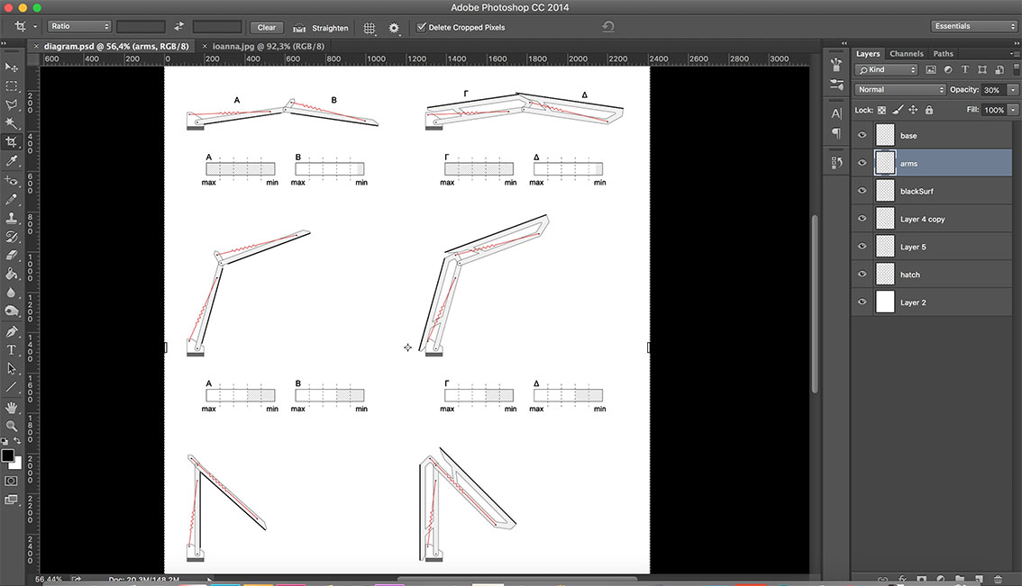
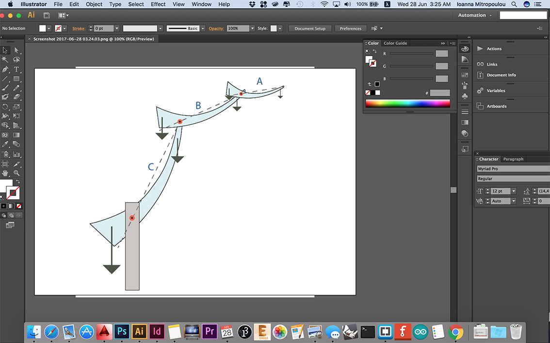
And here's another diagram I made on Illustrator
Here you can download the editable files:
counterweightsDiagr2.ai
counterweightsDiagr2.psd
Designing my final project
My final project looks like that in 3D.

It was developped throughout the fabacademy with a series of small (and bigger) models which can be found in my final project page, at the exploration process. I used Rhino to model it, and here you can download the Rhino file with the 3d model.
By the time I started designing this towards the end of the FabAcademy, I had already become very familiar with modeling in Rhino. Rhino was very helpful for this project because it had a lot of rotating parts, and Rhino has the necessary commands for such a project. Commands such as "rotate 3D","Duplicate surface border", and "project" were very useful.