6th Week, Electronics design
Making the Hello Echo PCB
This week we focused on electronics. Based on the experience gained from the 4th week, the goal was now to design a given circuit, and modify it adding a button and a led.
The initial board can be found here. For this assignment I fount particularly helpful this tutorial which explains the process step by step.
I decided to use Eagle to design my PCB, because it is free, and I could find a lot of resources and tutorials online about this software, such as this tutorial. The first step is to download and install the fab library. In this library are most of the components that are necessary for this assignment. Another library I also installed was the Adafruit library
In Egale there are two basic viewports: the schematic and the PCB layout. I started by adding all the components to my schematic, and connecting them as shown in the reference. When everything seemed correct, I opened the PCB Layout only to find a mishmash of lines and components, which I had to put in place.
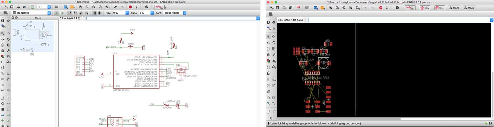
This was not an easy process, and what really helped me was when I changed the Grid settings so that I could have more accuracy with my lines (View/Grid/Size). Another big help was the possibility to hide and show elements from the layers tab, and the fact that the names and polarities appear on the wires and components when zooming in. After a lot of experimentation, I arrived in this. (I later found out that it was wrong though).
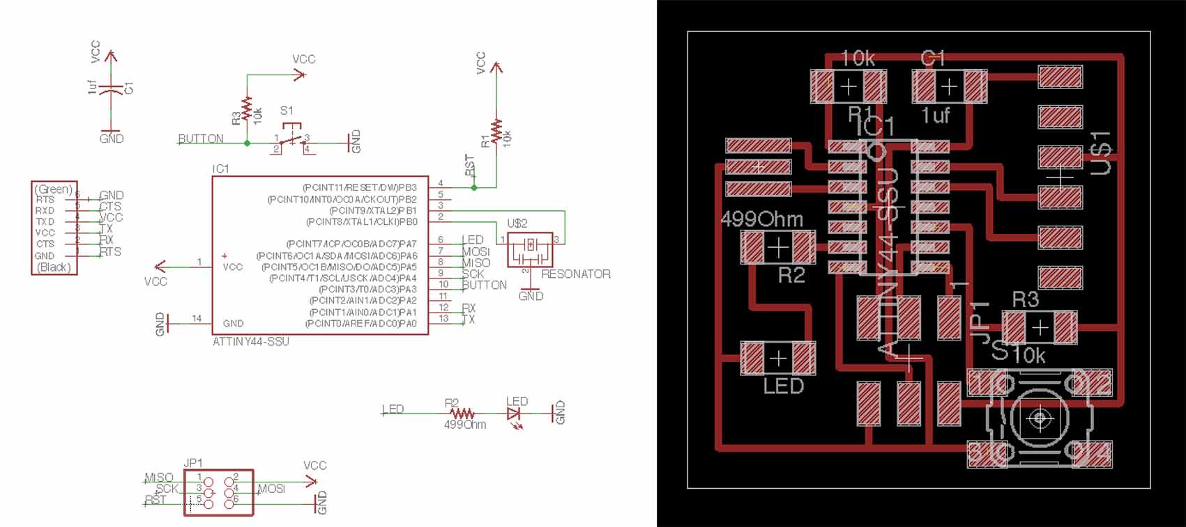
I learnt a lot from the process of redesigning the board and incorporating the button and LED. There are many rules concerning the minimum path dimensions, the clearances and the distance between the lines and the components which have to be respected in order for the board to work. Also, in order to add the LED and the button, I had to learn about the atTiny, its pins, what they do and how they should be connected with components.
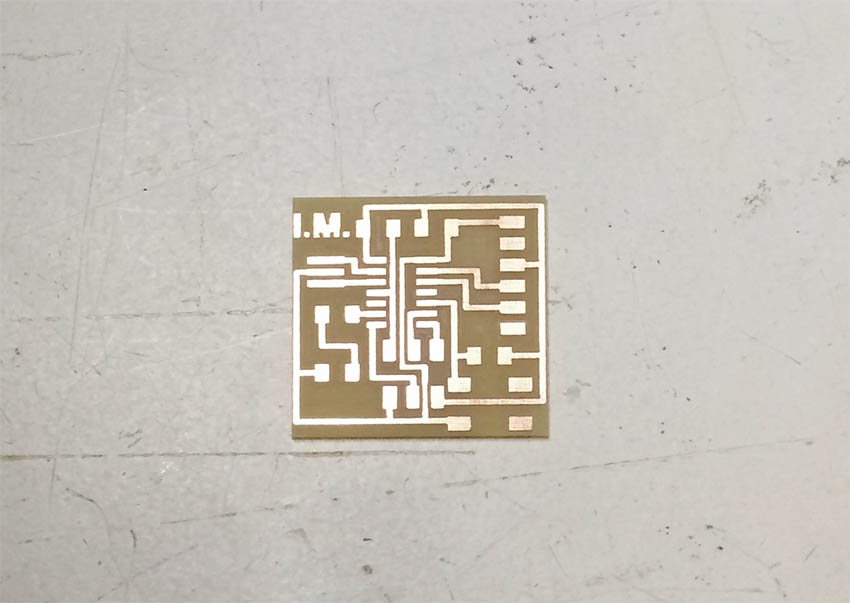
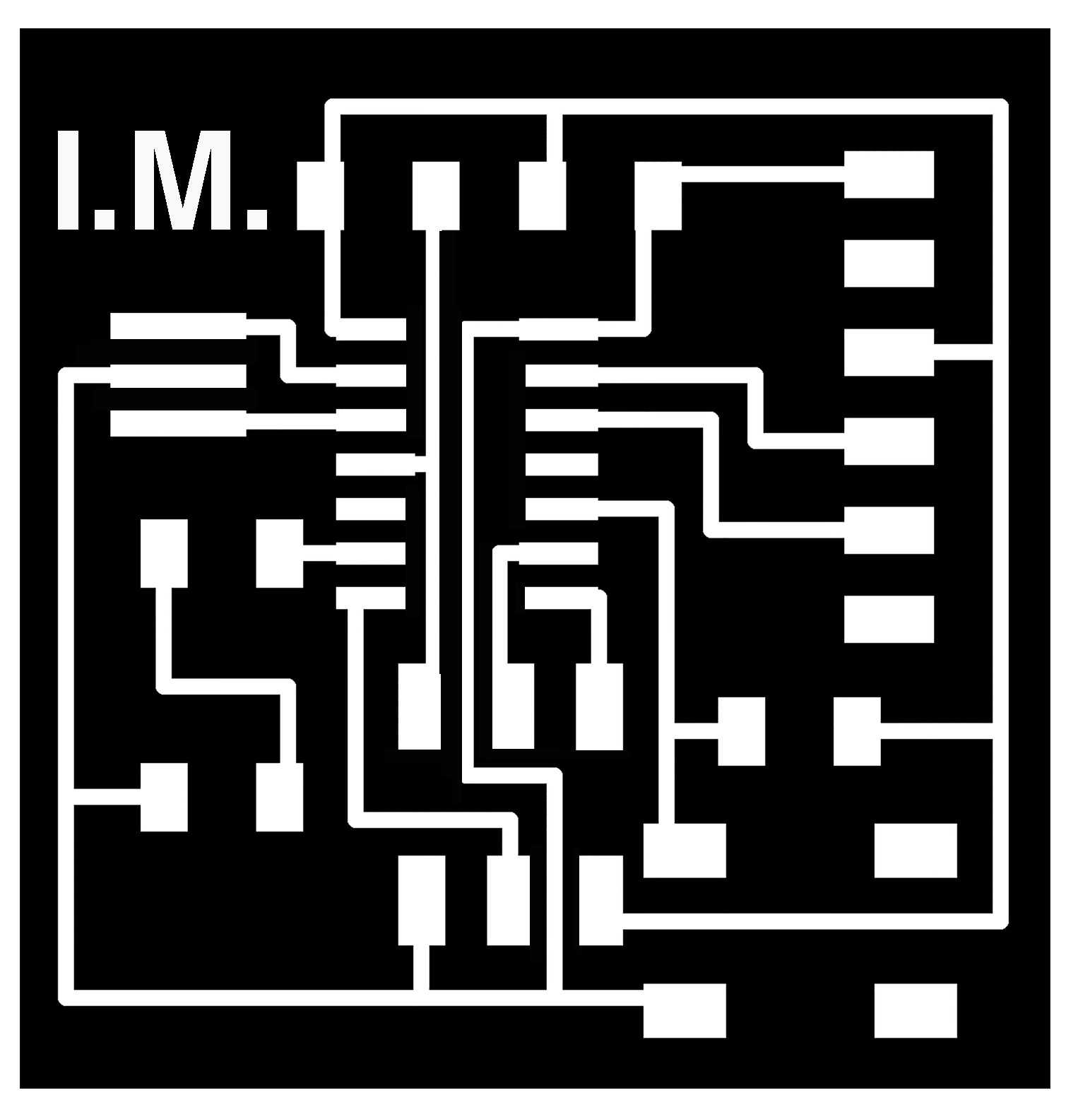
I added my initials using Photoshop, put the image in the right scale (the export from Eagle seems not to preserve scale) and then imported the .png on the fabmodules.io to get the file for the Monofab milling machine. After the milling was finished though, I realised that a lot of lines where not separated from each other. I tried to save the piece using a cutter to separate the lines, but it was impossible because the connected segments were really long. In fact, I could have predicted that if I had paid attention on the strategy calculated in fabmodules.org, where there was no tool path between some lines (those that, naturally, ended up not being separated).


Here you can download the png files that are necessary for the milling of this PCB: traces.png, outline.png
And here you can download the Eagle files: Board, Schematic
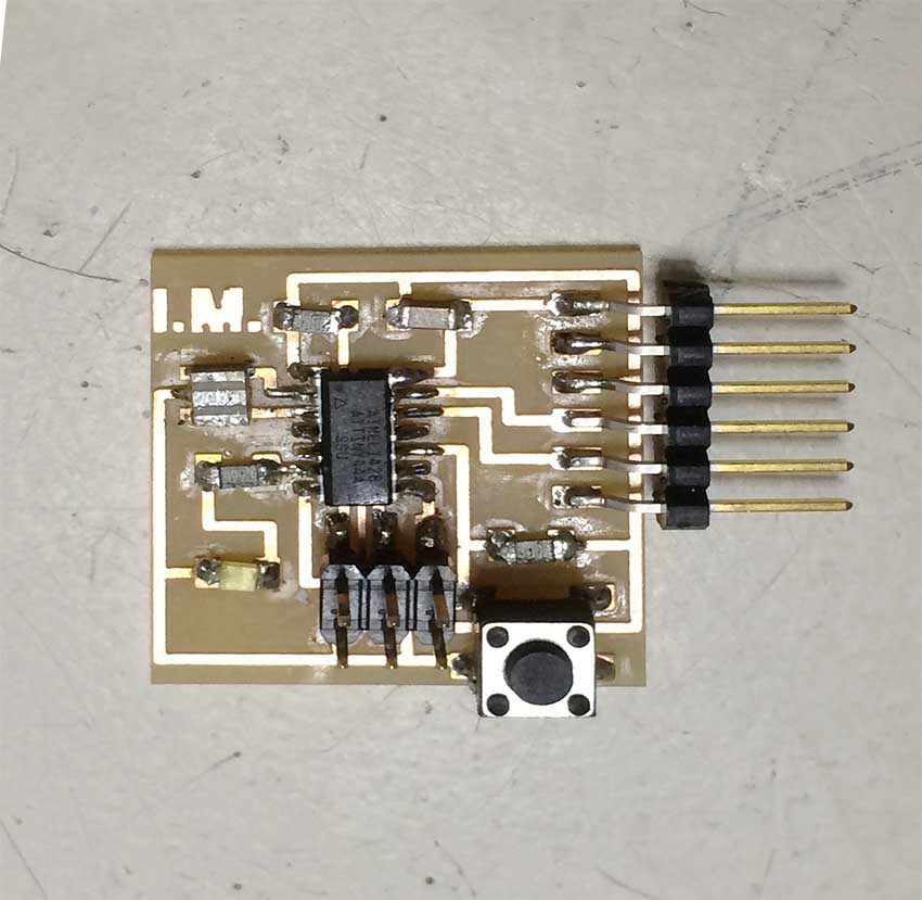
Next step, familiar from the 4th week, was the soldering. This time the difficulty of the process came as no surprise, as I’ve learnt to expect it by now. That did not stop me from making mistakes again, such as soldering the aTtiny44 in the wrong orientation. When I completed the soldering, I checked the connections with the multimeter and everything seemed fine. Here’s the final result, a bit dirty, but always shiny.
...Two weeks later...
It turns out I was too optimistic about my Hello Echo board. Unfortunately when I tried to program it in Week 8, it refused to be programmed. Despite doing everything correctly I always got an error from the computer.
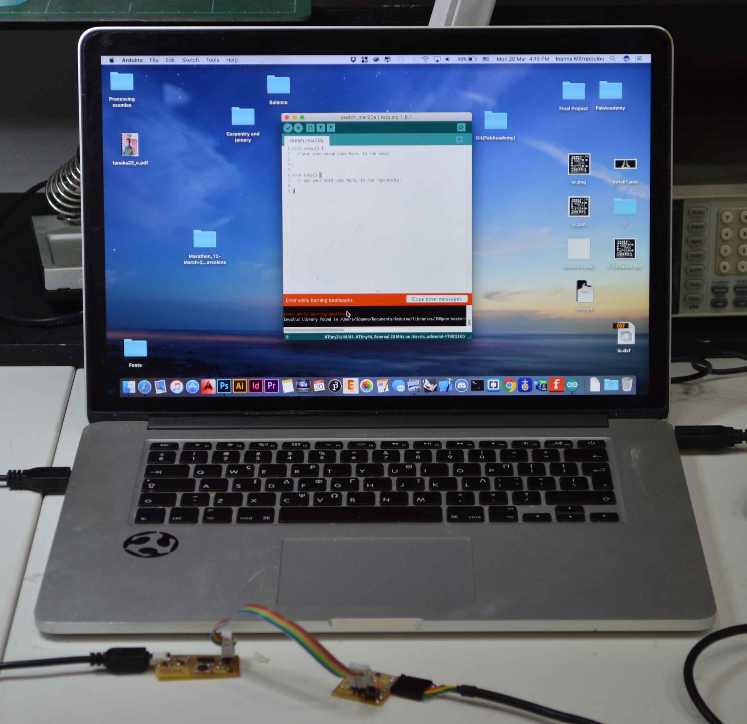
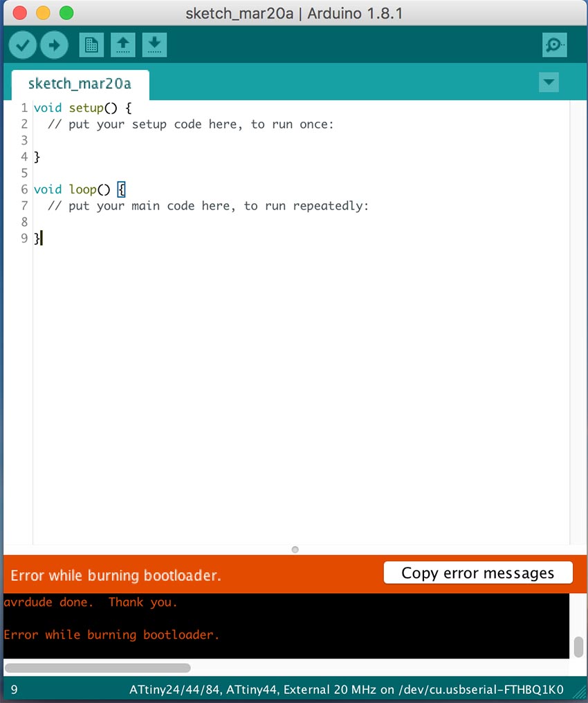
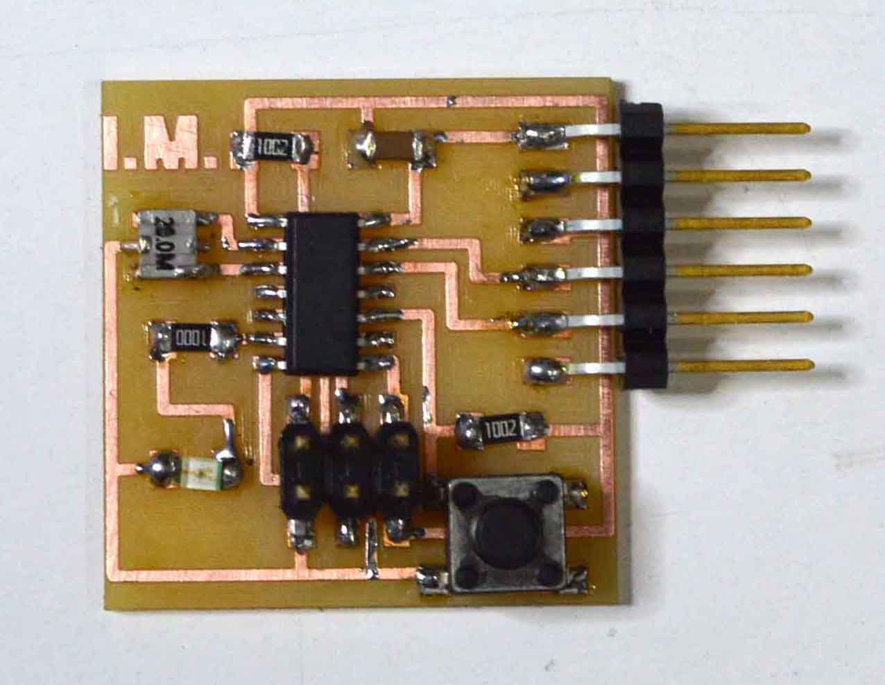
To narrow down the problem, I tried to program another HelloEcho in my computer, and it worked perfectly, so the problem was in the board. With help from the multimeter I found out that one of the atTiny’s pins was not connected as it should be. In an effort to fix that, I destroyed my atTiny. A few hours later, and after a series of similar bad interventions on the board I decided I should re-do it from scratch, saving as many components as possible from the old one. And so it happened. Here’s my brand new HelloEcho board which unarguably has been soldered much better.
In Week 8 you can find how I programmed it using Arduino IDE and C.