13th Week, Input devices
Potentiometer controlling LED brightness

This week we focused on Input devices. The assignment was to add a sensor to a microcontroller board that we have designed and read it.
I decided to use the PCB I designed during week 10 (Output Devices) for my final project to control my servos and connect them with bluetooth to my phone. You can find all the information about the design and the fabrication of the PCB on Week 10. Apart from the pins specifically designed for the servos and the bluetooth, the PCB has a few extra digital and analog I/O which I am using for this week's assignment.
Reading a Potentiometer (analog input)
A potentiometer is a simple sensor that provides a variable resistance, which we can read into the Arduino board as an analog value. When its position is changed, its resistance changes and the Arduino receives values from 0 to 1023.
In this example, that value controls the brightness of a LED. The potentiometer is connected to an Analog I/O, and the LED is connected to a digital I/O. The brightness takes values from 0 to 255, while the potentiometer sends values from 0 to 1023. This is why we need to use the “map” function with the following syntax:
brightness= map ( sensorValue, 0, 1023, 0, 255);
So the code looks like that:
The connections are very simple. Potentiometer is connected to VCC, GND and the A0 analog I/O of the PCB. The bluetooth is connected to VCC, GND, the TX of the bluetooth to RX of the PCB, and the RX of the bluetooth to TX of the PCB. Finally the LED is connected to GND via a 221Ω resistor and to pin 13 of the arduino. (alternatively, instead of connecting an external LED, you can observe the changes in brightness on the built-in LED of the PCB, which is also connected on digital I/O 13).
Here’s how it works.
Potentiometer controlling LED brightness with ioanduino from Ioanna Mitropoulou on Vimeo.
Here you can download the files for the ioanduino
traces.png
partlist.pdf
schematic (eagle file)
board (eagle file).
And here you can download the code for the potentiometer: potentiometer.ino
Making the mini board
Another thing I tried to do for this week's assignment was to fabricate a mini version of the ioanduino board, using the atTiny instead of the atMega. This was because I could see that for many projects, such as this week's assignment, I don't really need the atMega and all its pins. So I thought that it would be a good idea to make a cheaper and smaller version for such projects.
The atTiny is a microcontroller I have worked a lot with in previous weeks, so it was not very difficult to design this board. Here's the atTiny Datasheet, always very useful when designing a board. The software I used was once again Eagle.
Schematic
Board
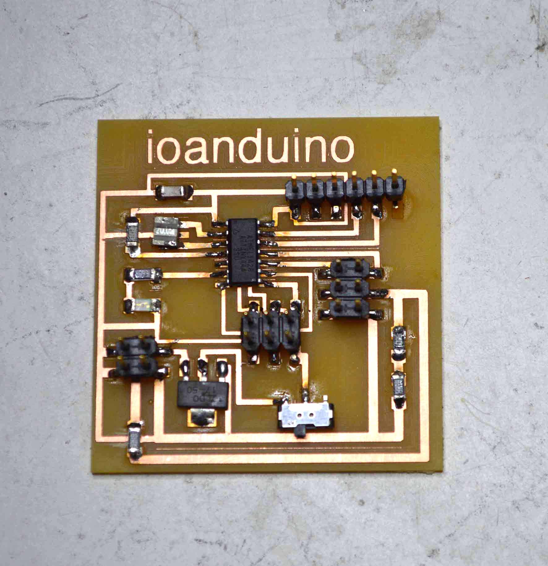
This board keeps the basic functions of the previous one: it has external power source, a switch and available pins for input and output. However it has not been designed to connect with bluetooth. It needs and FTDI and a fabISP to burn the bootloader, and then it can be programmed using the fabISP.
Here you can download the files for the ioanduino Mini
traces.png
schematic (eagle file)
board (eagle file).
I used the monofab to mill it.
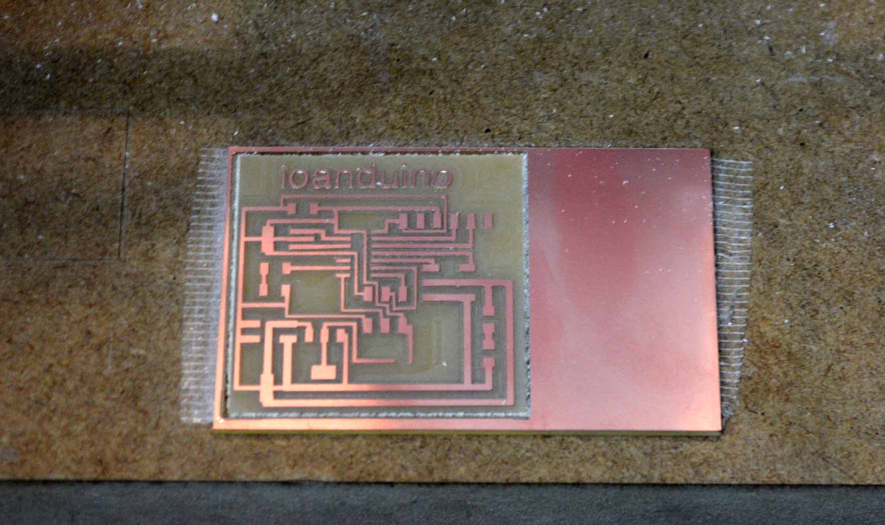
Here's the final board.
And here's a comparison of the mini version and the previous big version.

The steps for programming it are the same as with the previous boards. First you connect it with teh FTDI and the fabISP, and you need to burn the bootloader using the Arduino IDE. For more information about this process, visit the Week 8, embedded programming. Here are the necessary settings on the arduino IDE for burning the bootloader, and later programming the board.

Programming the board

In order to program it, we need to know the atTiny pinout.

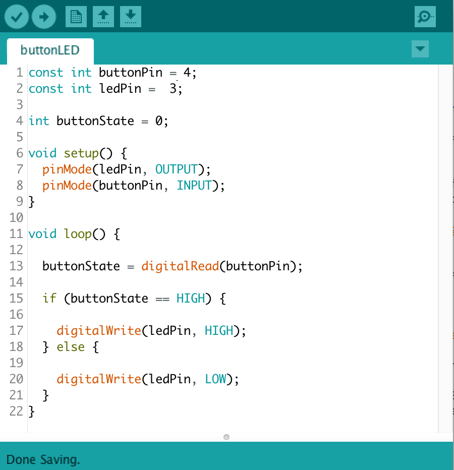
I tested the board using a button as an Input, and a LED that is turned on and off. The connections are simple: the LED is connectd to the pin 3 of the atTiny and GND with a resistance, and the button is connected to the pin 4 of the atTiny and GND. If the external power source is connected to the board then it needs no other cable to work, but it can also be alternatively powered with the FTDI.
Here's what the code looks like:
You can dowload the code here.