17th Week, Applications and Implications
-What is the project all about?
In my final project I am focusing on kinetic architectural elements and experimenting with the interaction of the human with the architectural shell. The interest is set on achieving low-energy movement by using a smart geometrical configuration, and on fabricating almost all the necessary parts inside the fabLab.
This project will be part of my diploma project for my architecture diploma, which I will present in the National Technical University of Athens in July 2017. My proposal for my architecture diploma is a pavilion in front of one of the lakes of Ciutadella park in Barcelona, which offers shadow and space for seating, and uses kinetic panels, the prototype of which I am developing in the fab Academy as my final project.
So in summary, my final project for the fabacademy is a kinetic shading panel that consists of two arms and uses spring forces as counterweights to minimise energy requirements and reliance upon the actuators. The user can interact with it with his phone via bluetooth using the project's application.
REFERENCES
Interactive architectureOverall we can say that architecture is desired to be interactive for two main groups of reasons: pragmatic and humanistic.
Humanistic: Sociology-psychology. Affect human behaviours, their sensing and understanding of space, allow control and personalisation, create attachment-bonding with the space.
Pragmatic: adaptability-optimisation. Improve conditions (temperature, shading, space etc), energy efficiency.
There are numerous examples of interactive architecture. Adaptive houses, moving walls, smart facades, interactive floors, lights, appliances and spaces. I will only present a few that are more relative to my project.
(click on the names to see more details for each reference)
Interactive Pavilions
on smart geometrical configurations for efficient movement
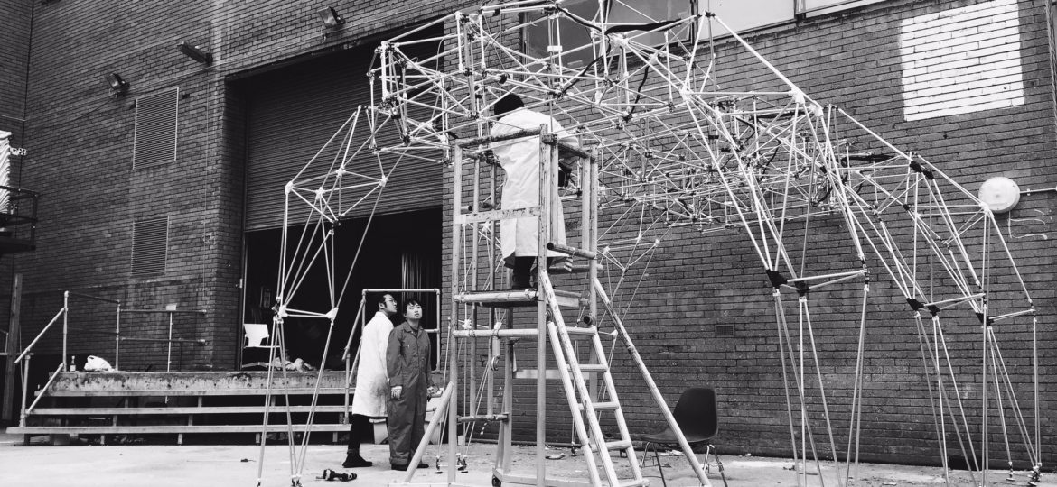
The Golem is a project developed by students in UCL that uses low cost 3D printing and open hardware tools such as Arduino, to create assemblies of low cost air-muscle actuators and mechanical joints.
Golem RoNomad - Pneumatic Walking Pavilion from siyuan jing on Vimeo.
For more information: http://www.interactivearchitecture.org/lab-projects/golemby ARUP, on engaging in interaction with the user

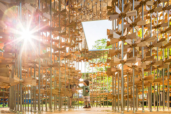
The Pinwheel pavilion is a self-supporting interactive structure built from bamboo, steel, timber and aluminum. It consists of multiple mills supported by a forest of pillars. Each wheel has been systematically aligned to others on the rod so that as visitors spin a single piece, it triggers the movement adjacent pieces. It serves as a metaphor for the ability to positively influence the wider community — the activity of one person can trigger a chain reaction that affects a great number of people.
by Aedas Architects in Abu Dhabi, 2012
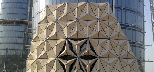
Completed in June 2012, the 145 meter towers’ Masharabiya shading system was developed by the computational design team at Aedas. Using a parametric description for the geometry of the actuated facade panels, the team was able to simulate their operation in response to sun exposure and changing incidence angles during the different days of the year.
by Enrique Jan + Jean Nouvel in Paris, 1987

In the early eighties Jean Nouvel in conjunction with Architecture-Studio won the competition to design what would become the Institut du Monde Arabe. It was conceived during the Grands Projets, a major development initiative headed by the French government. Its purpose was to create a destination devoted to the relationship of the Arab culture with France.
A main feature and innovative element of the IMA is the advanced responsive metallic shading mechanisms of the south façade. The system incorporates several hundred light sensitive diaphragms that regulate the amount of light that is allowed to enter the building. During the various phases of the lens, a shifting geometric pattern is formed and showcased as both light and void. Squares, circles, and octagonal shapes are produced in a fluid motion as light is modulated in parallel. Interior spaces are dramatically modified, along with the exterior appearance.
Use of counterweights in architecture for efficient movement
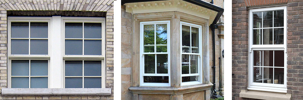
A sash window, traditionally fund in often found in Georgian and Victorian houses, is made of one or more movable panels. To facilitate it opening and closing, the weight of the panel is balanced by a counterweight concealed within the window frame. In contemporary such windows counterweights have been replaced by spring forces. A well designed and balanced window requires little or no effort to operate and remains open or closed as desired.
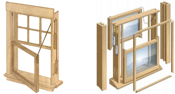
There are four important components to a properly designed weight and pulley window balance system:
Weights
The combined weight of the counterweights must match the full weight of the moving panel to which it is attached.
Sash Pulleys
The diameter, weight capacity and friction of the pulleys affect the design
Chain (or Cord)
The cord must be strong, lightweight and elastic, yet non-deformable
Counterweight Access
Access to the mechanism is essential so that adjustments can easily be made when it is put out of balance
References:
Sash/counterweight window, wikipedia
Weight and Pulley Balance Systems for Wood Windows
How to Fix a Window Counterbalance
Double Hung Window
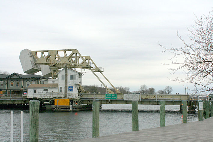
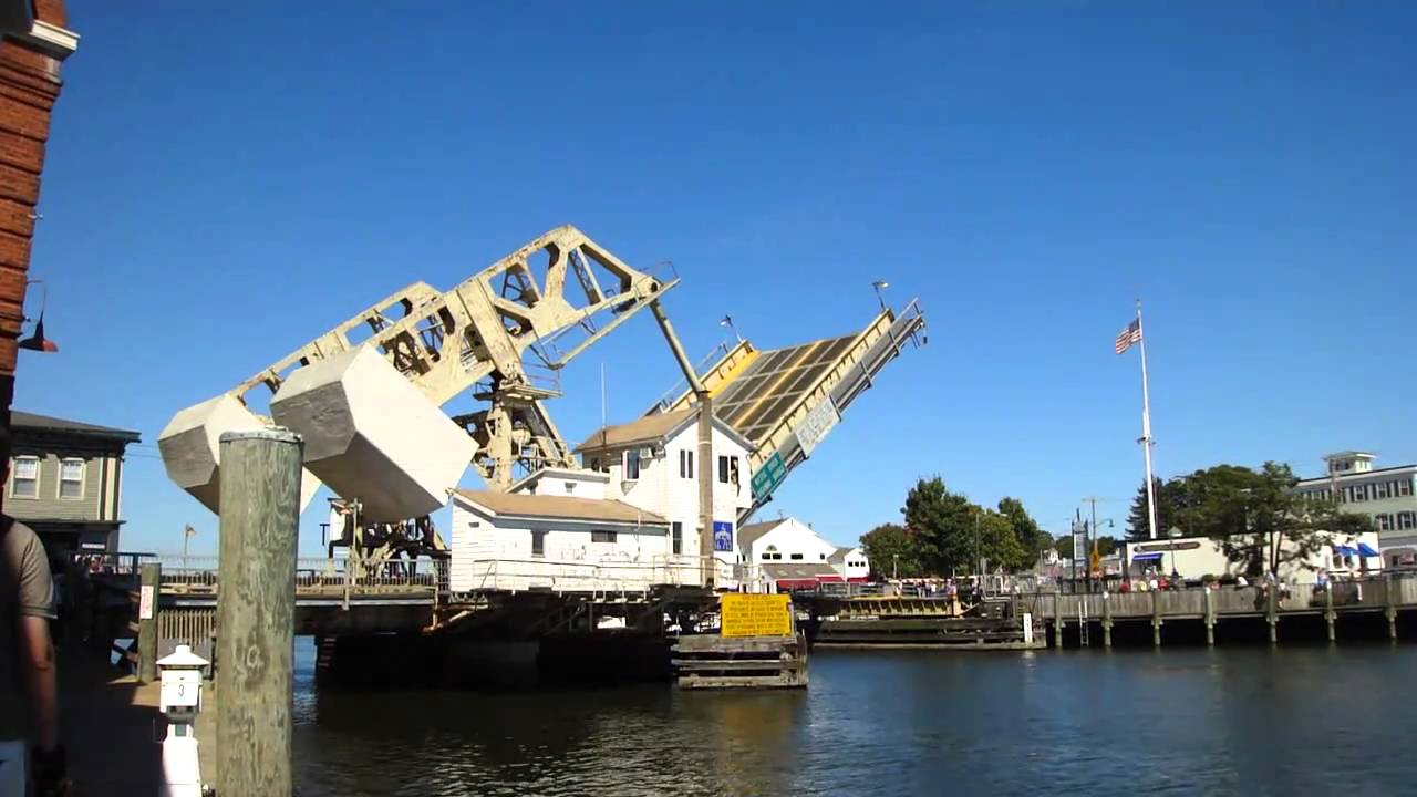
The Mystic River Bascule Bridge was designed and built in 1920 in New York, and it is still working very well. It carries vehicle and foot traffic via a 10 meters wide road. It uses two massive counterweights that continuously balance its weight, and allow it to swing upwards to provide clearance for boat traffic.

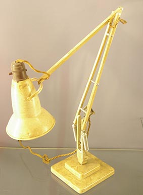
The Anglepoise lamp is a balanced-arm lamp designed in 1932 by British designer George Carwardine. It has adjustable folding arms which are balanced (also called floating arms), which are constructed so that the force due to gravity is always counteracted by springs, regardless of the position of the arms.
There are many possible configurations, some of which are very nicely summarised here: https://en.wikipedia.org/wiki/Balanced-arm_lamp
THE PROTOTYPE
My prototype is an improvement of the CNC week’s assignment. It looks like that.

This model is smaller and it has a lot of changes concerning the mechanism, the position of the shading surfaces, the base and the materials used. Here you can download the Rhino file with the 3d model, with the shapes for the laser and the CNC for all the pieces of my prototype.
THE PARTS
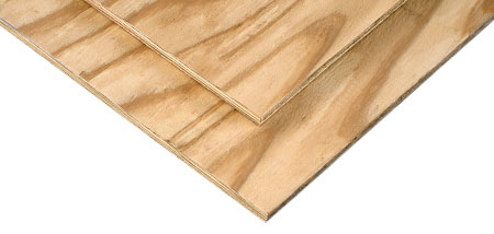
The main material I am going to use to construct it is 9mm plywood, which was ordered by the fablab from Gabarro. This will be cut on the CNC.
I will also need long bolts with diameter 6mm, which I will make by cutting long ribbed bars using appropriate the hand tools of the fablab for cutting and smoothing metal. In the same way I will cut a few 4mm bars I need for the attachment of the gears to the arms. All those will be bought from a local vendor of metal parts.

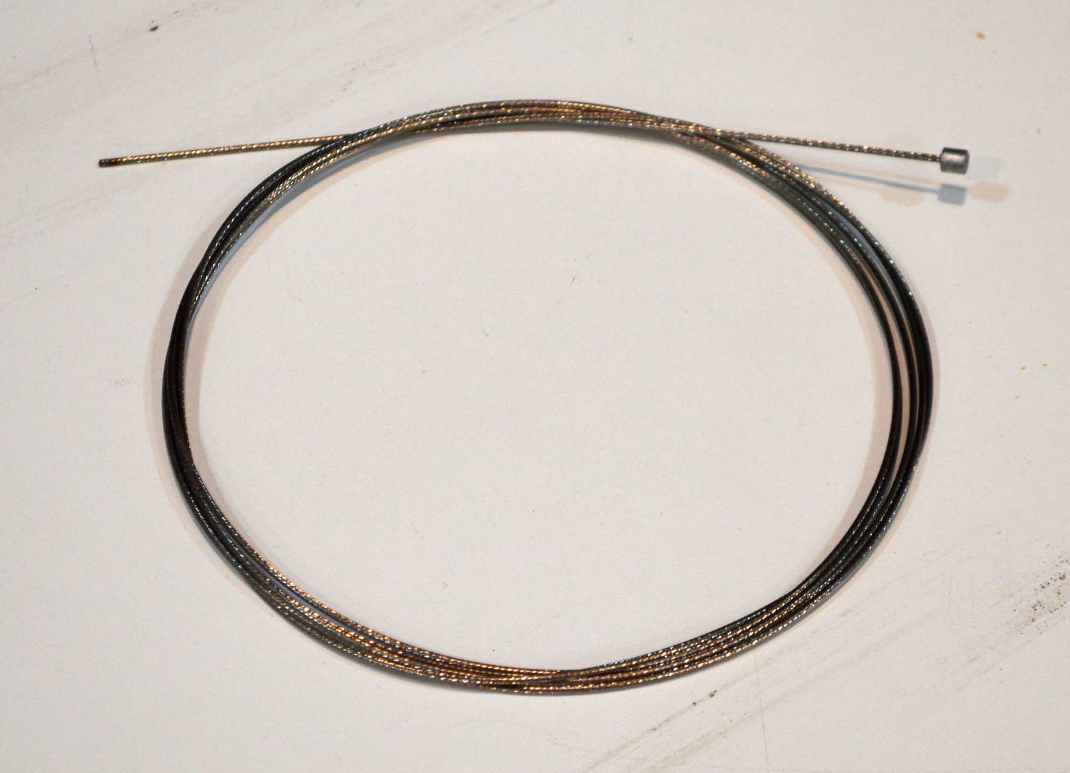
For my thread, after a long research, I decided to use the metallic thread that is used in the breaks of bicycles. It is smooth, thin elastic and very strong and non deformable when bended. The disadvantage? It is expensive. I bought it from a local bicycle store.
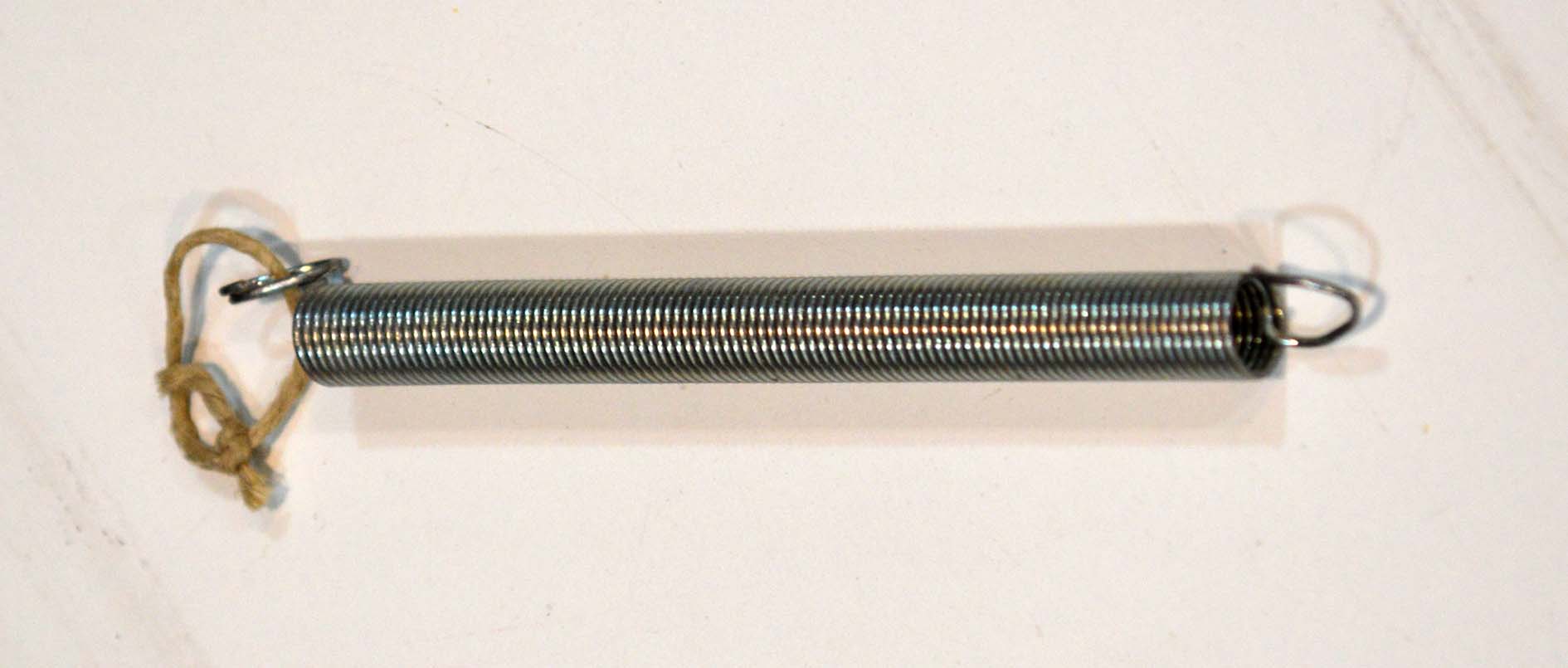
The springs were bought from a local vendor, and their material properties where tested using a lasercut scale. You can find out more about the process here.
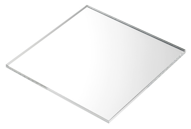
Apart from that, I will use 6 and 3mm acrylic to cut the gears, the pieces to attach the gears to the arms, and the pieces to attach the motors to the base and lower arm. These will be cut on the laser. I will not buy this material because I found some nice scraps on the fablab.
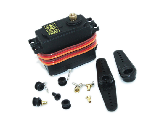
Which brings me to the next necessary component, the motors. I will use two servos of 180 degrees rotation angle, 100mA operating current, 3-7.2V operating voltage and 13KG/cm operating torque. They were bought from Diotronic, and here’s the exact model.
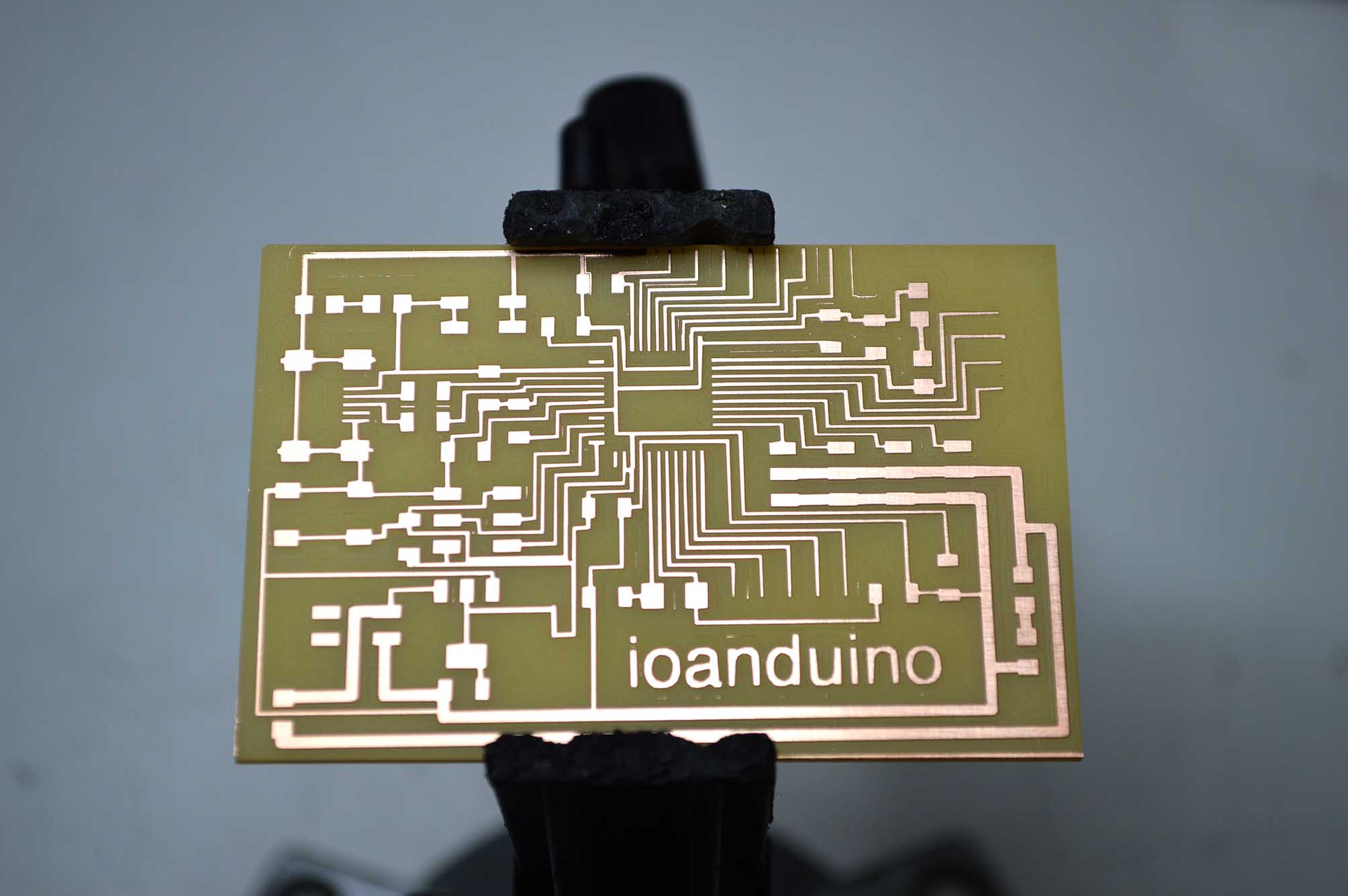
To control the motors I will use a PCB that is the improvement of the board I made for my assignment during the Output week. It is called ioanduino, and it is based on Arduino Leonardo, with the atMega32u4 as its core. You can find more information about its fabrication and programming in that week’s page.
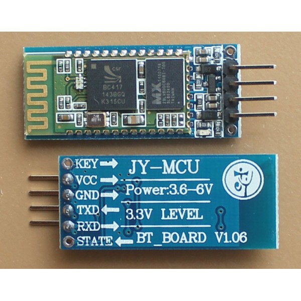
To send data to the ioanduino, I am using a bluetooth HC-05 module, which I became acquainted with in the Networking and communication week. There you can find all the information about the module and how it can be connected with my board. I bought the bluetoth module from Diotronics, but you can also find it on ebay in a better price.
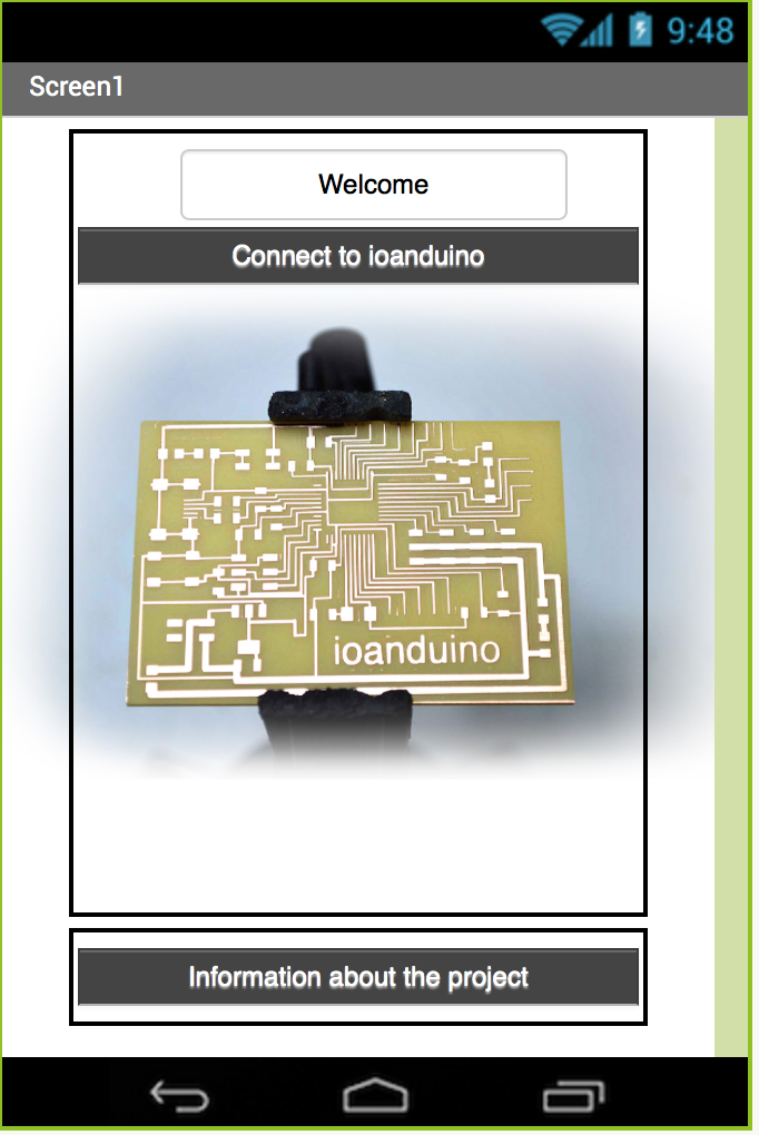
The bluetooth receives data from the application I designed during the Application design week using the MIT App Inventor. There you can find the blocks for the AppInventor, the code for the ioanduino, and a detailed explanation of how those two communicate using a 2-byte protocol.
THE COST
Roughly speaking, around 60 euros.
Plywood--------------------------6 €
two motors-----------------------30€
HC-05 bluetooth module-------9€
metallic parts---------------------4€
metallic thread-------------------7€
springs---------------------------4€
acrylic----------------------------0€ (I managed to find some wonderful scraps!)
ioanduino------------------------(around) 2€
Tasks that need to be completed- Schedule
At the moment my project is already quite advanced. I have fabricated all the pieces, and finished the electronics. What is more, I've started putting the parts together, but I still have to work on this. I believe I will need around 5 days to complete the model, and another week for troubleshooting. If all goes accoring to plan, I will finish a week before the final presentations, and I'll use this time to work on the video and the presentation.
Some questions still remain to be answered:
-how to measure the efficiency of the mechanism
-how to balance the springs better
-how to avoid the servos getting stuck
-how to present the project
How the project should be evaluated
The project should be evaluated in relation to the initial questions and the goals that were set. It is not perfect, but I believe it does answer the questions that were asked at the begining and it does achieve the goals. Those are:
-balaced arms with springs, fabrication of all the parts so that the prototype works. Done.
-rotation of the arms with low power servo motors. Done.
-working PCB for controlling the motors. Done.
-working application for wireless connection with the PCB using Android. Done.
Further questions and improvements are of course necessary. I discuss those in my final project page (conclusions and further research paragraph).