
This work is licensed under a Creative Commons Attribution 4.0 International License.
Final Project
Contents
Final prototypeThe idea
Fabrication
Electronics and Application design
Video
Photos of the finished prototype
Conclusions and further research
Why I loved doing the FabAcademy
An architectural proposal based on my final project
Project Development
Project development
The exploration Process
Adding the motor
Fabrication of the third model, CNC milling
Defining the spring's physical properties
The physics behind the springs mechanism
Moving on to balanced arms with springs, second model
First model with counterweights
Using grasshopper to explore the subject
First thoughts
The idea
In this research I am focusing on kinetic architectural elements and experimenting with the interaction of the human with the architectural shell. The interest is set on achieving low-energy movement by using a smart geometrical configuration, and on fabricating almost all the necessary parts inside the FabLab.
In other words, I am trying to come up with ways to achieve kinetic architecture with simple and cheap means inside a fabLab, so that both their fabrication and operation can be affordable by anyone.
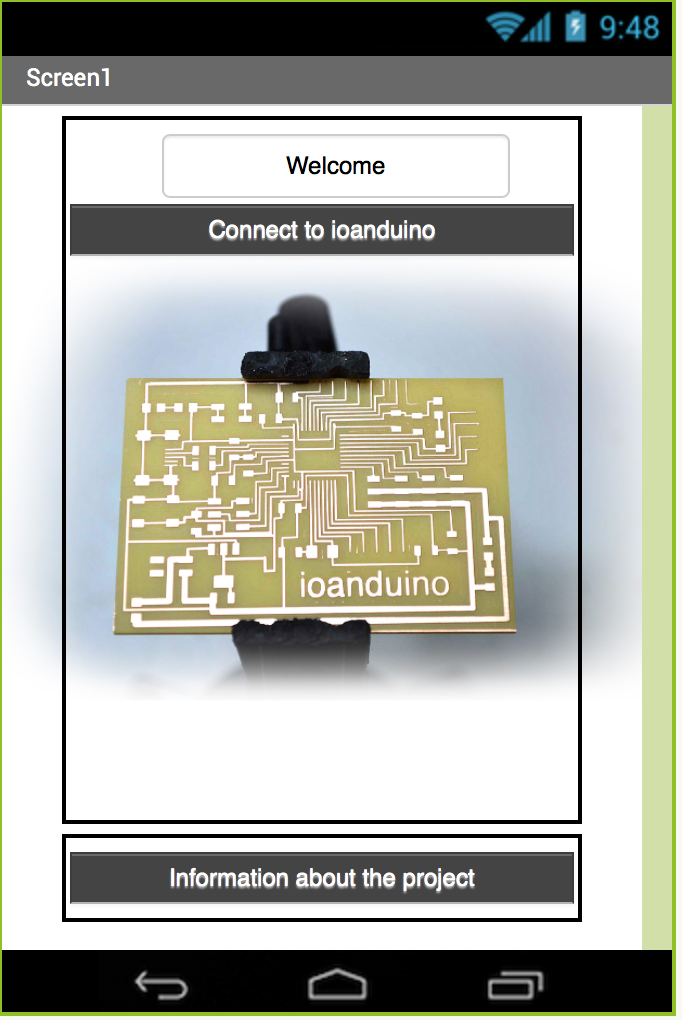
For this I am developing a kinetic shading panel that that consists of two arms and uses spring forces as counterweights to minimise energy requirements and reliance upon the actuators. The user can interact with it with his phone via bluetooth using the project's application.
This project will be part of my diploma project for my architecture diploma, which I will present in the National Technical University of Athens in July 2017. My proposal for my architecture diploma is a pavilion in front of one of the lakes of Ciutadella park in Barcelona, which offers shadow and space for seating, and uses kinetic panels, the prototype of which I am developing in the fab Academy as my final project.
Fabrication of the final prototype
My prototype is an improvement of the CNC week’s assignment. I am using many of the techniques I mention in that week's page, as well as a few new that I explain here. The list of all the necessary parts, where come from and which techniques are used, as well as my references, can be found in the Week 17 (Applications and implications) page.
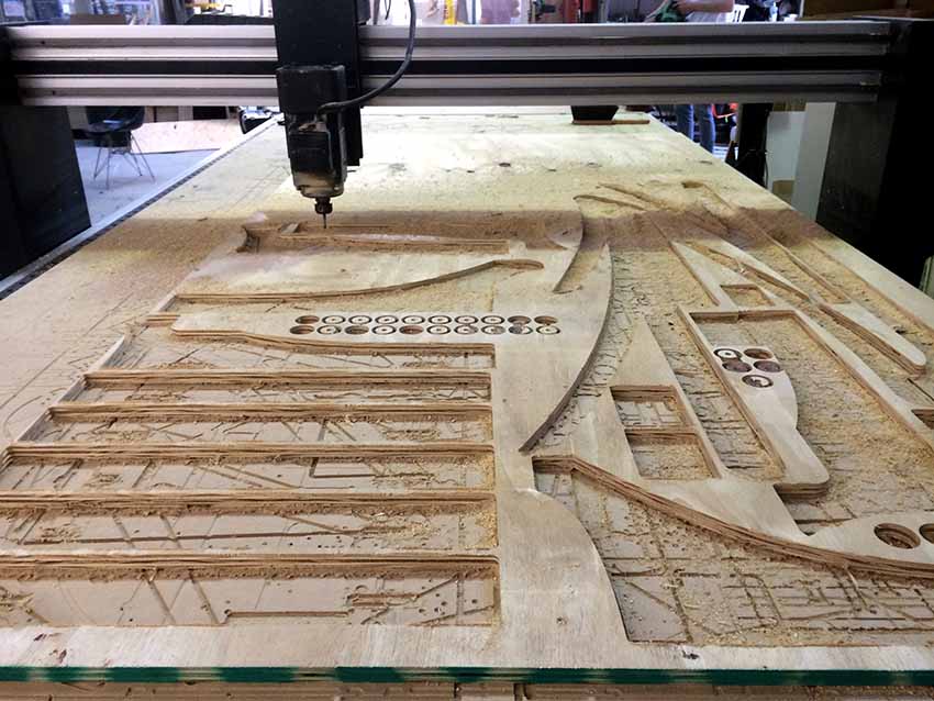
CNC MILLING
The main material I used was 9mm plywood. This was cut on the Shopbot CNC using a 6mm flat mill. The strategy was calculated using the RhinoCam plugin.
Here you can download the rhino file with the RhinoCam strategy:RhinoCAM.3dm


And this is me happily removing my pieces from the board.

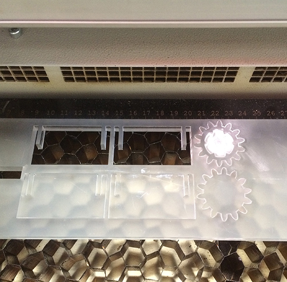
LASER CUTTING
For the details (the gears, the pieces to attach the gears to the arms, and the pieces to attach the motors to the base and lower arm) I used acrylic with thickness from 3 to 8 mm. This was cut on the Trotec laser cutter.
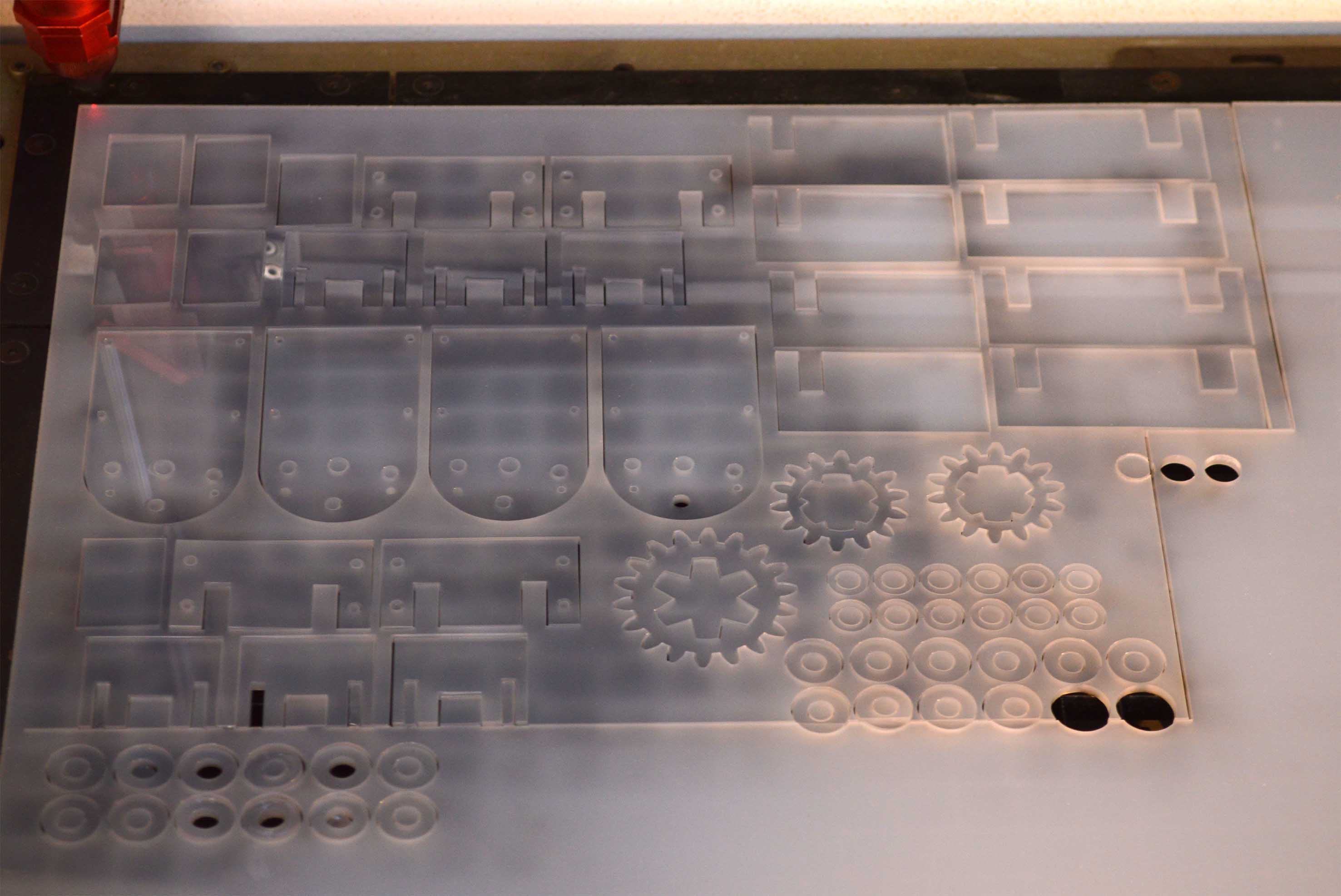
For the gears that are attached to the motors, instead of cutting two 3mm layers and glueing them together as I did in my last model, this time I cut one piece of 8mm acrylic, and engraved it so that it can be attached on the motor. This worked much better. You can see the process on the following video, behind the reflection of my hair on the laser cutter's glass.
Fabrication of gears from Ioanna Mitropoulou on Vimeo.
The motor's case that allows it to connect rigidly with the arms was the same I had used in my previous models.

For the shading surfaces I used 4mm mdf wood which was also cut on the Trotec.

All the parts can be found sorted according to the material in this rhino file: piecesForCutting.3dm
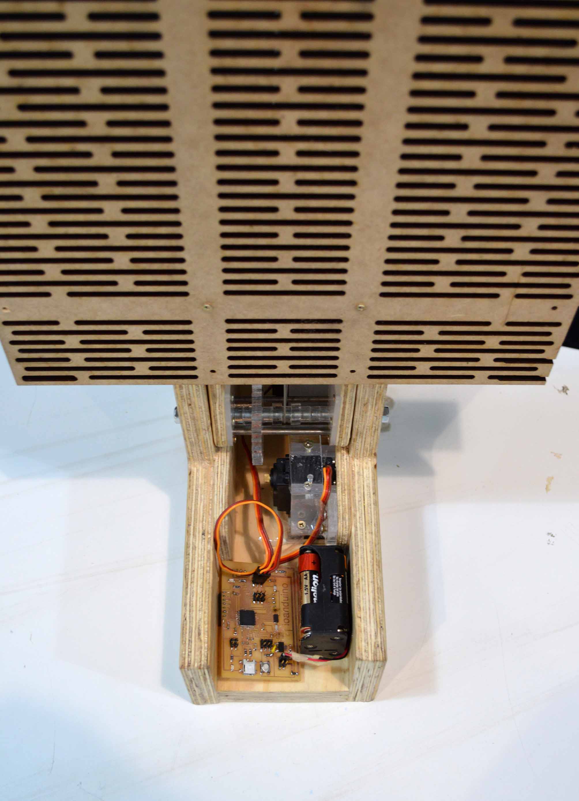
Electronics and Application design
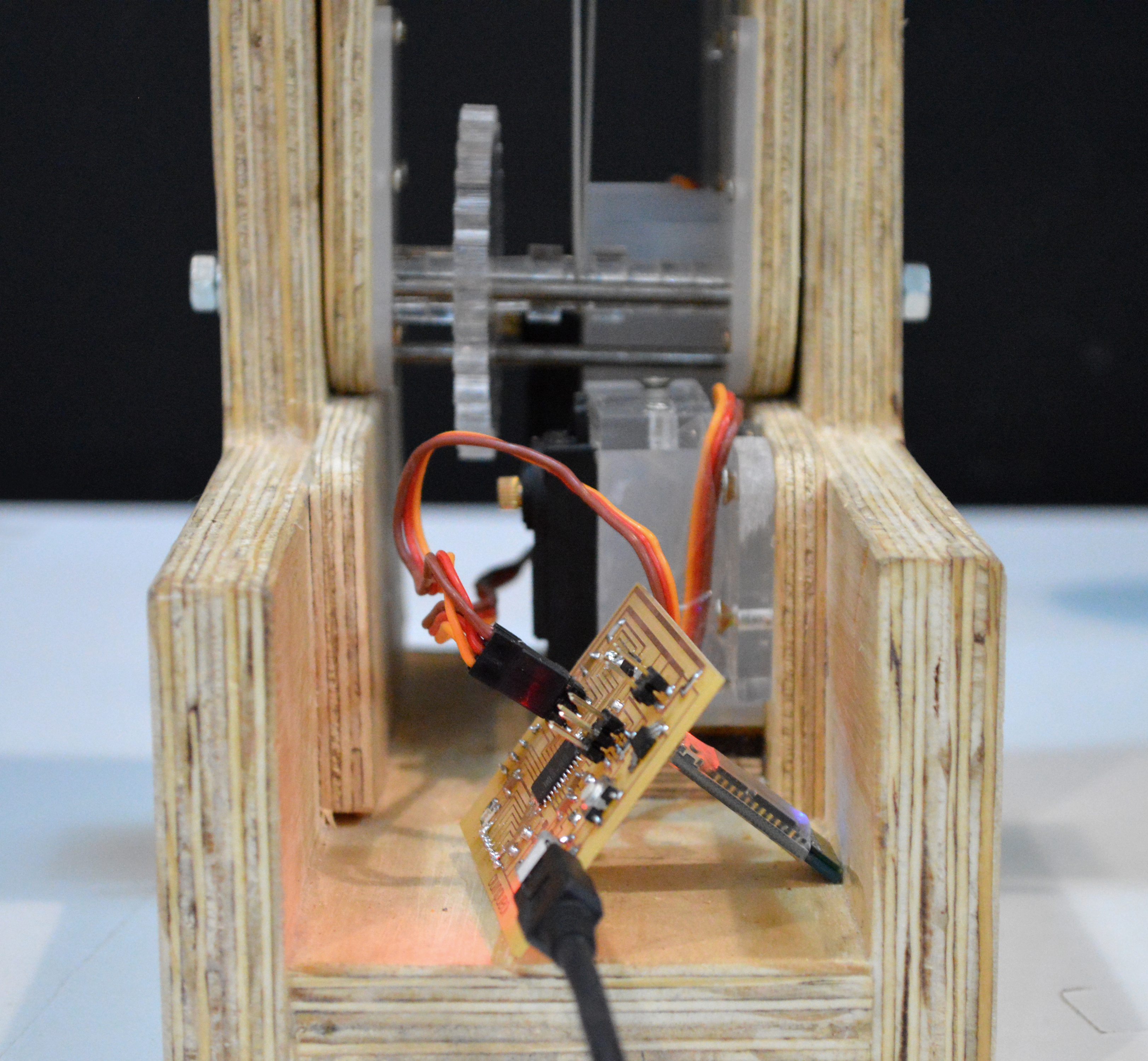
To control the motors I used a PCB that is the improvement of the board I made for my assignment during the Output week. It is called ioanduino, and it is based on Arduino Leonardo, with the atMega32u4 as its core. Everything about the fabrication and programming of both versions is documented with detail in that week’s page.

Here you can download the ioanduino files
traces.png
partlist.pdf
schematic (eagle file)
board (eagle file).
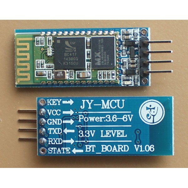
In order to send data to the ioanduino, I am using a bluetooth HC-05 module, which I became acquainted with in the Networking and communication week. There you can find all the information about the module and how it can be connected with my board to allow sending and receiving data.
The bluetooth receives data from the application I designed during the Application design week using the MIT App Inventor. There you can find the blocks for the AppInventor, the code for the ioanduino, and a detailed explanation of how those two communicate using a 2-byte protocol.
Here you can download the arduino code: _ioanduinoBluetooth.ino
The Video
BEHIND THE SCENES
To make my video I used a Nikon D3100 to shoot, a tripod, and pretty much every corner of the fab academy room of the Barcelona fablab. I therefore have to thank all my fellow students who tolerated me during that process.
I am quite experienced with making videos, so for this task I used the software I am most familiar with, the Adobe Premiere Pro.Editing videos is one of my favourite things to do.
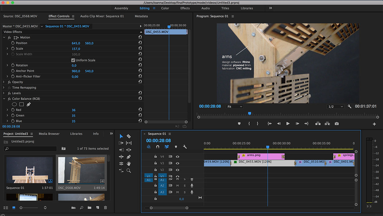
I always start with a plan of all the different shots I need, even though I never follow it. When I finish with my "plan", I improvise. This leads to a lot of gigabytes of very little use, inside which a few nice accidental images can hopefully be found.
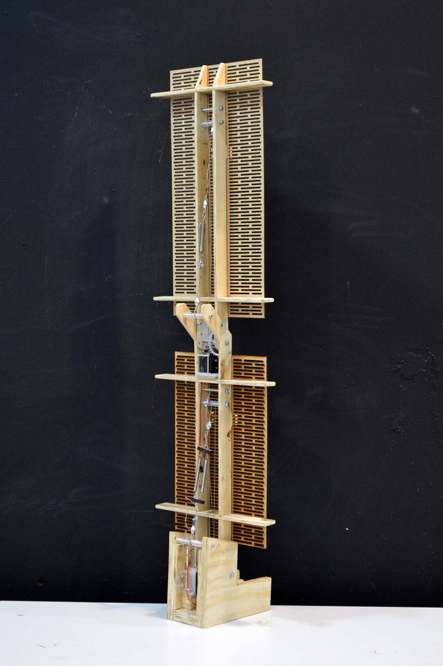
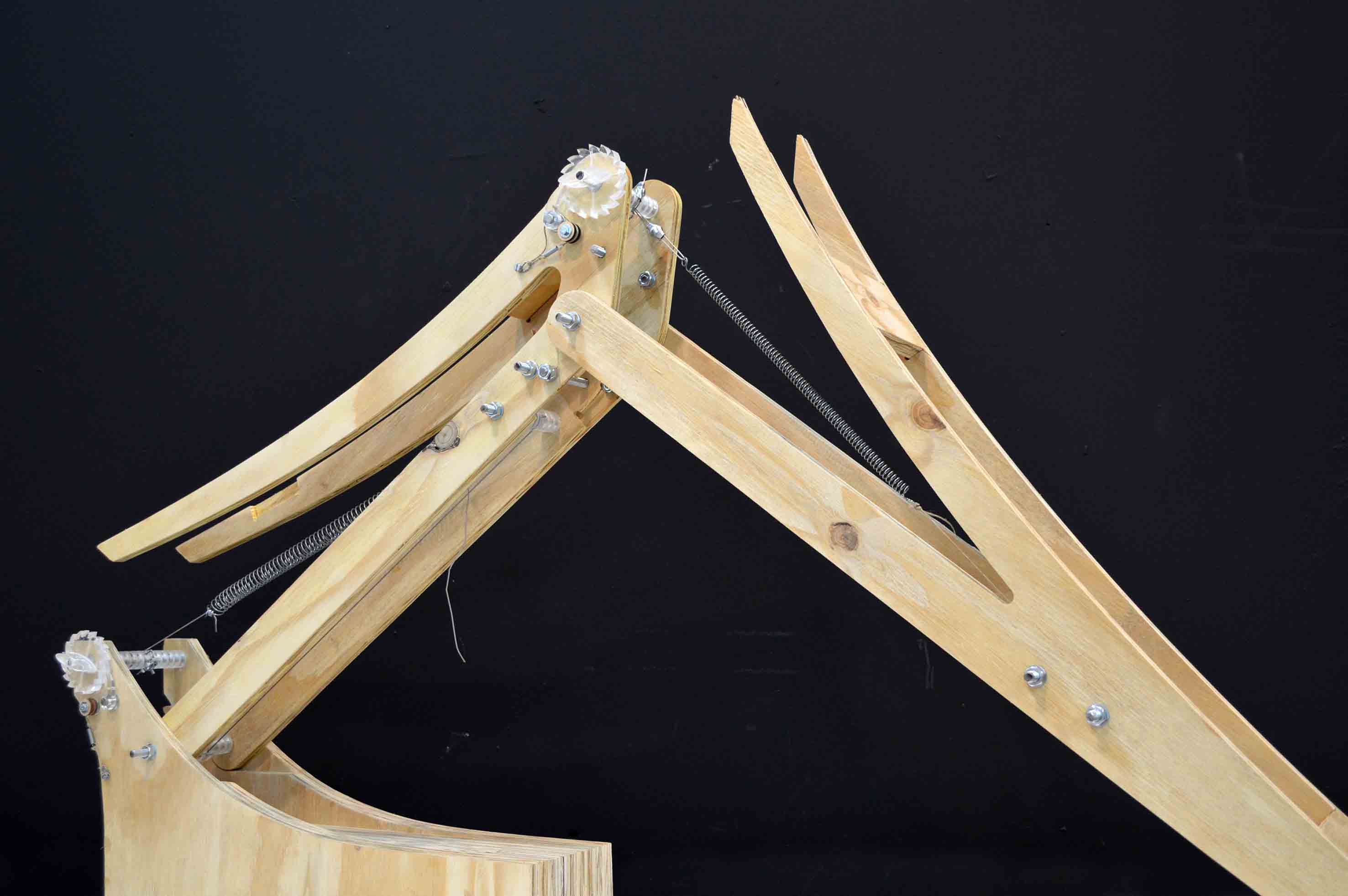
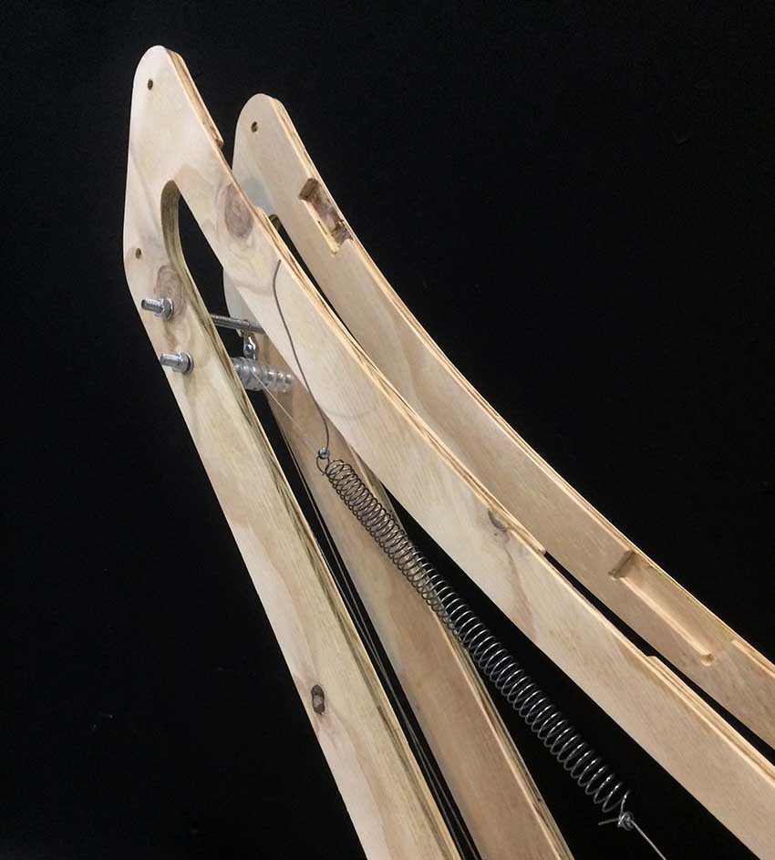
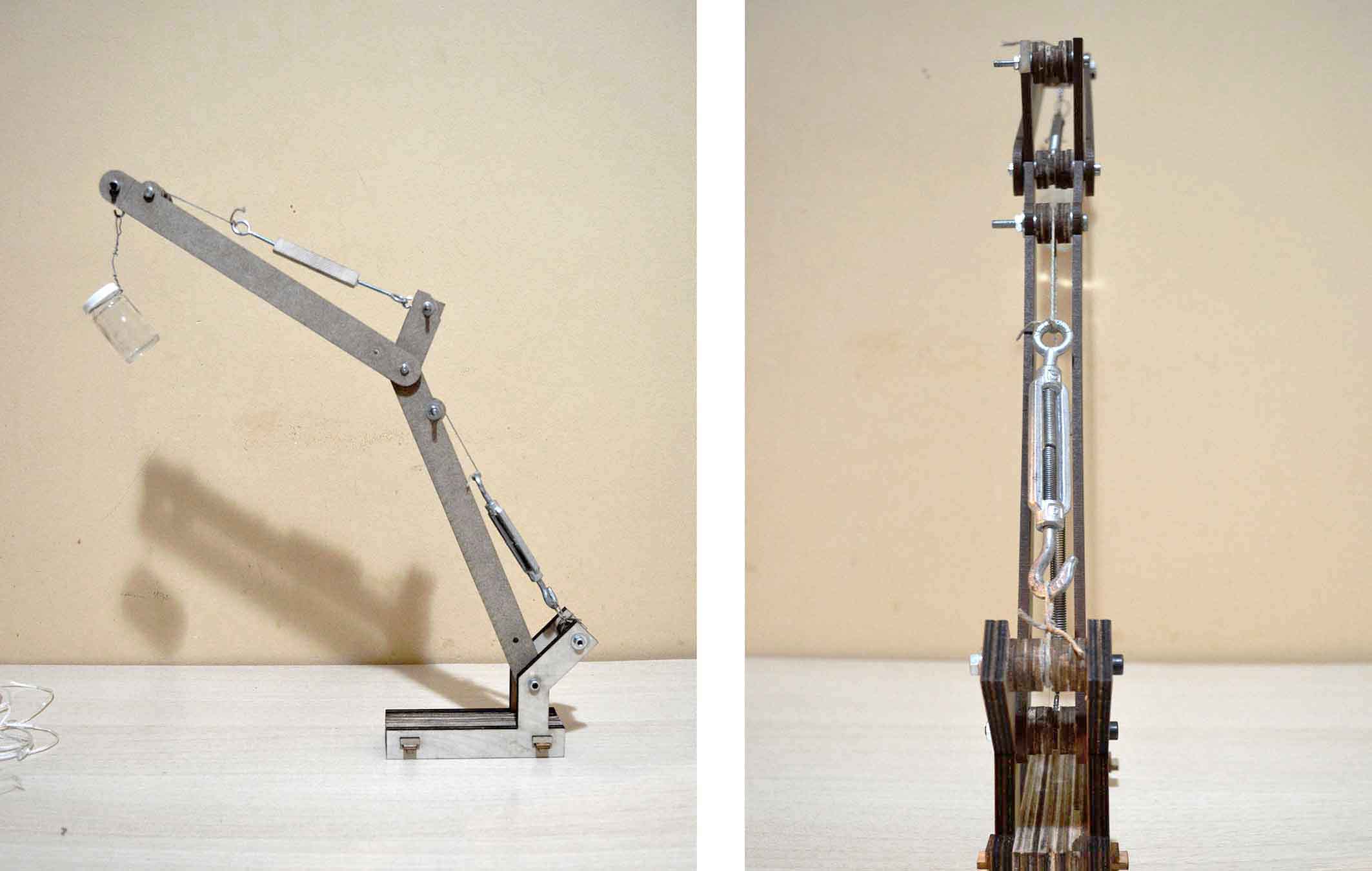
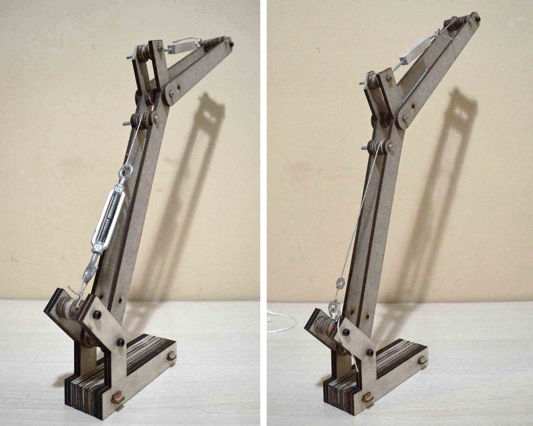
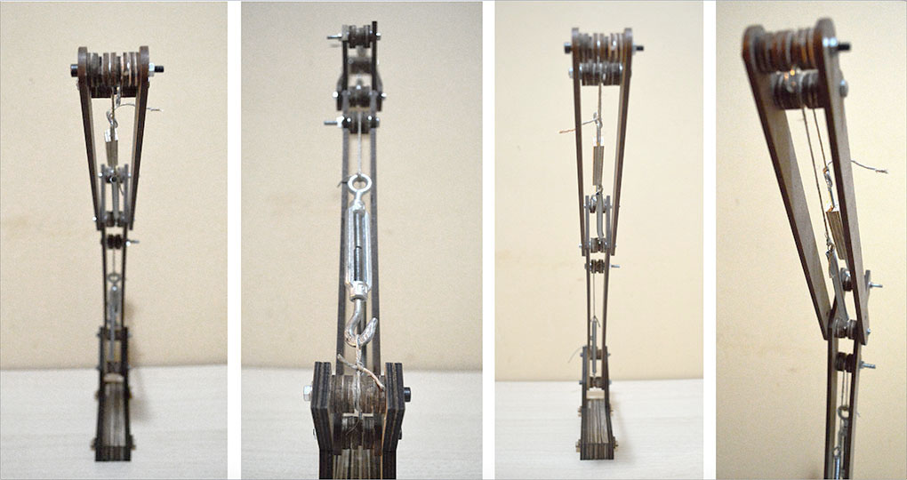
Photos of the finished prototype


Conclusions and further research
I consider this prototype to be successful because the goals I had set were achieved:
-Low energy and smooth movement of heavy objects
-Working prototype
-PCB designed according to the needs of the project
-Application that allows interaction with bluetooth
-Fabrication of all the parts inside the fablab
Nevertheless there are a few unsolved issues which should be addressed in future research. Those concern both the hardware and the software.
MODEL
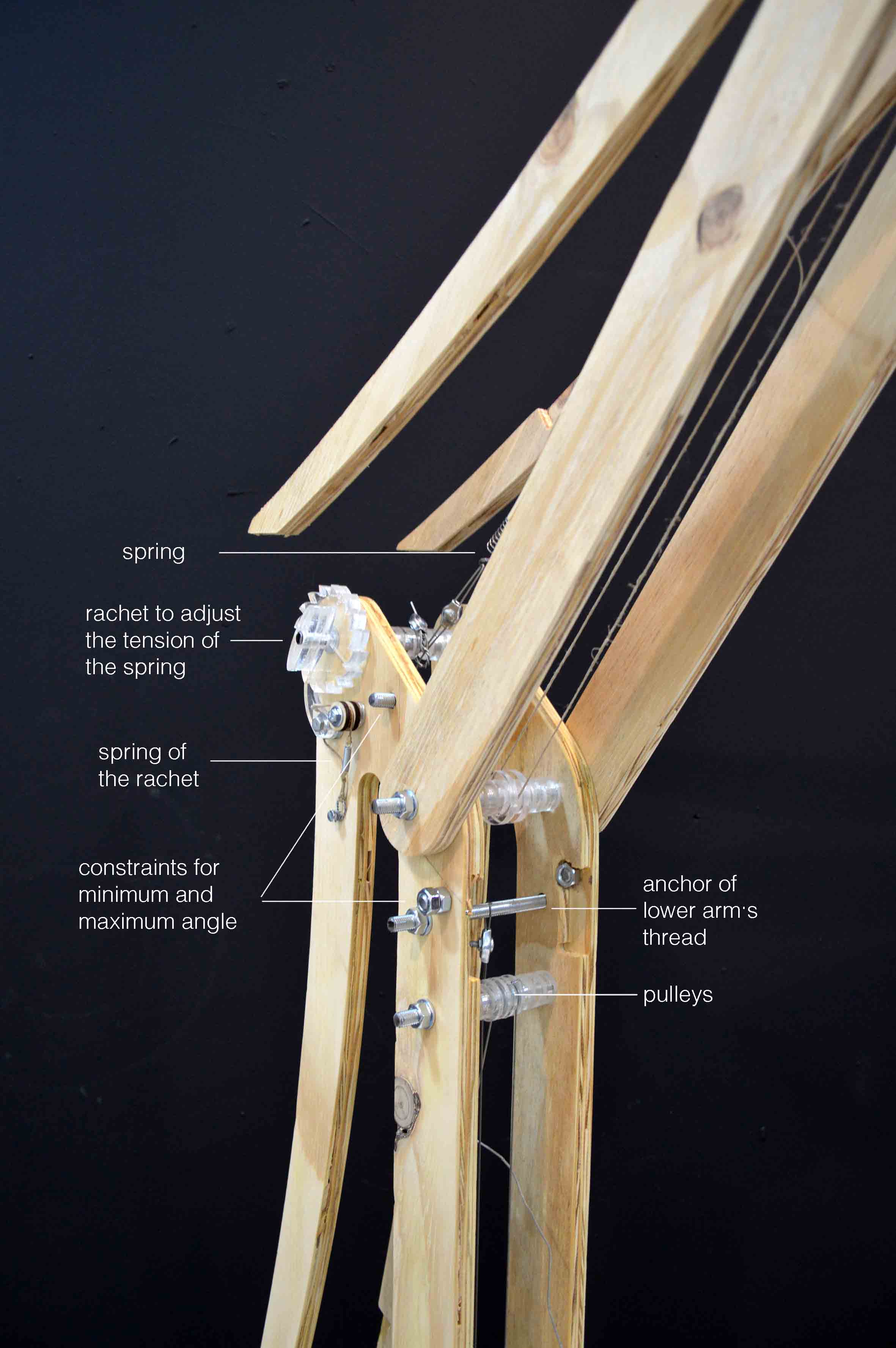
One problem observed is that the arms can not be set and be stable in the intermediary positions. Apart from the constraints of the minimum and maximum angle, there are no other constraints in the rotation of the arms. Thus it is possible that rotating the upper arm will result in undesirable movement of the lower arm, or that with a little bit of wind the whole prototype moves. At the moment the only thing holding it in place is friction (which I went into great pain to minimise) and the motor. These are not enough. There should be a mechanism that allows it to lock in intermediate positions, in order to become more stable and reliable.
Another problem is that there is a little bit of play in the joints of the arms, as a result apart from moving up and down, they also slightly tilt left and right. If you see the video carefully, you will see it. This should be addressed by rethinking those joints, and basically the whole design. In order to fix it there should be more area of parallel surfaces touching or/and tighter joints. But it is not as simple as that, because this would increase friction, and thus the required energy for the movement.
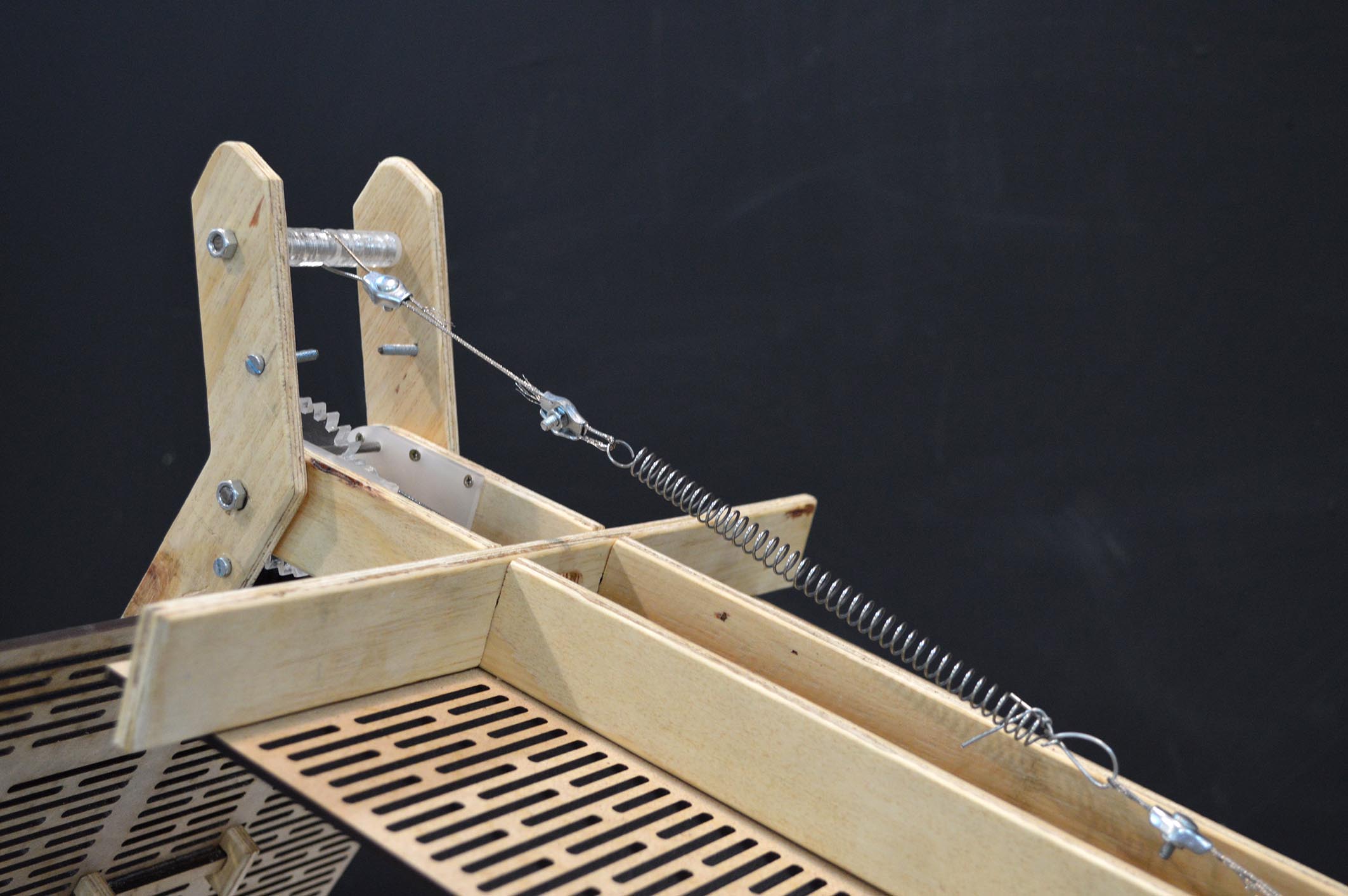
What is more, if the weight on the arms changes, the prototype is out of balance. This means that the springs do not help as much as they could the rotation, and that in certain positions (usually the ones close to the maximum positions), instead of helping the motors, they actually act in a negative way, adding up to the gravity force. Another improvement therefore would be to add a mechanism that allows for automatic tension adjustment on the springs. (I tried to do that in my first big model with the ratchet mechanism, you can find more about it here, but the idea didn’t make it to the final prototype). This would allow the prototype to carry weights that variate without falling out of balance.
After the problems are solved, it would be very interesting to add more arms in order to create a more agile structure.
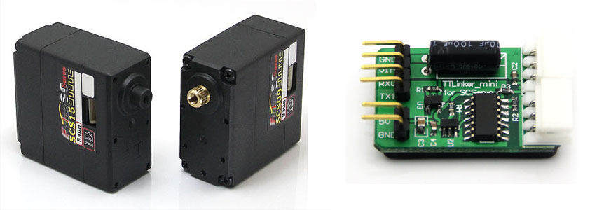
MOTORS
The servos I used are not strong enough to move the arms without problems. Sometimes they got stuck. I believe that I should pass on to another family of servos. What I am considering is the family that is called SCS servos, which are stronger, more reliable (and more expensive). The problem is that those motors require a TTLinker, which has to be connected with the TX and RX pins of the atMega (pins currently used for the bluetooth communication). As a result, to use those motors the ioanduino has to be redesigned.
PCB
I am very happy with the way the PCB works, which is not surprising taking into consideration that I stayed as loyal as I could to my reference: the arduino Leonardo. Still, many things could be improved. One of them is the pins that the motors connect with. At the moment there is one voltage which connects to all the motors, so if one of them has different voltage requirements, it cannot connect with the others. This is not a problem now, but if the extra mechanisms I mention above are added, then more and different motors will be needed.
Why I loved doing the FabAcademy
Participating in the fabacademy and developing my final project was a very interesting process during which I learnt so many new things, that I feel like an entire new world of possibilities have opened to me.
I must thank all the the FabAcademy advisors, teachers and technicians of the FabLab Barcelona, because without their help this would not have been possible.
What I really liked about this course was the freedom it gives to the students to chose their project, and to customise the process, the schedule, and the final goals according to their needs. Another benefit was that we were able to see other students' work very often. As far as the complexity of the projects is concerned, in the class we had all the spectrum, from very basic to really advanced and complex projects. For me, being in the middle, it was very beneficiary to be able to see other student’s work because I really learnt from that. Also, it was a good motivation for me to work harder.
Finally, during FabAcademy I started a new collection: interesting scraps or mistakes produced by the lasercutter. I already have a few beautiful pieces.
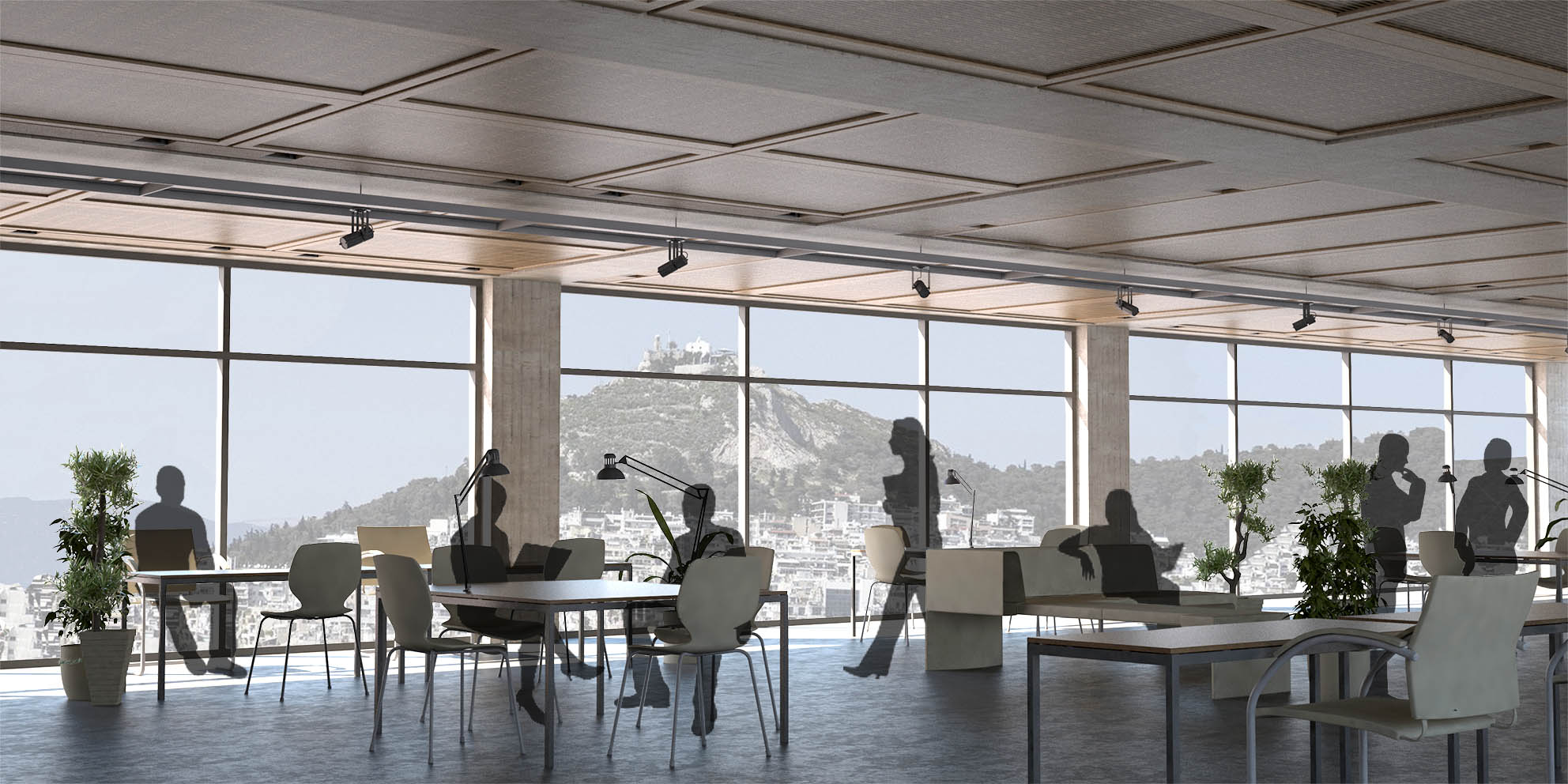
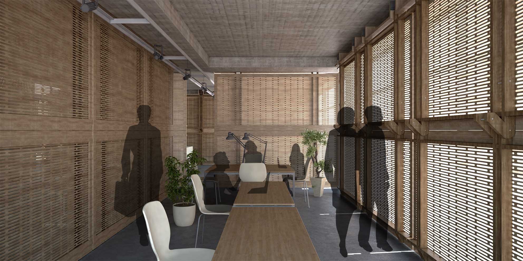
An architectural proposal based on my final project
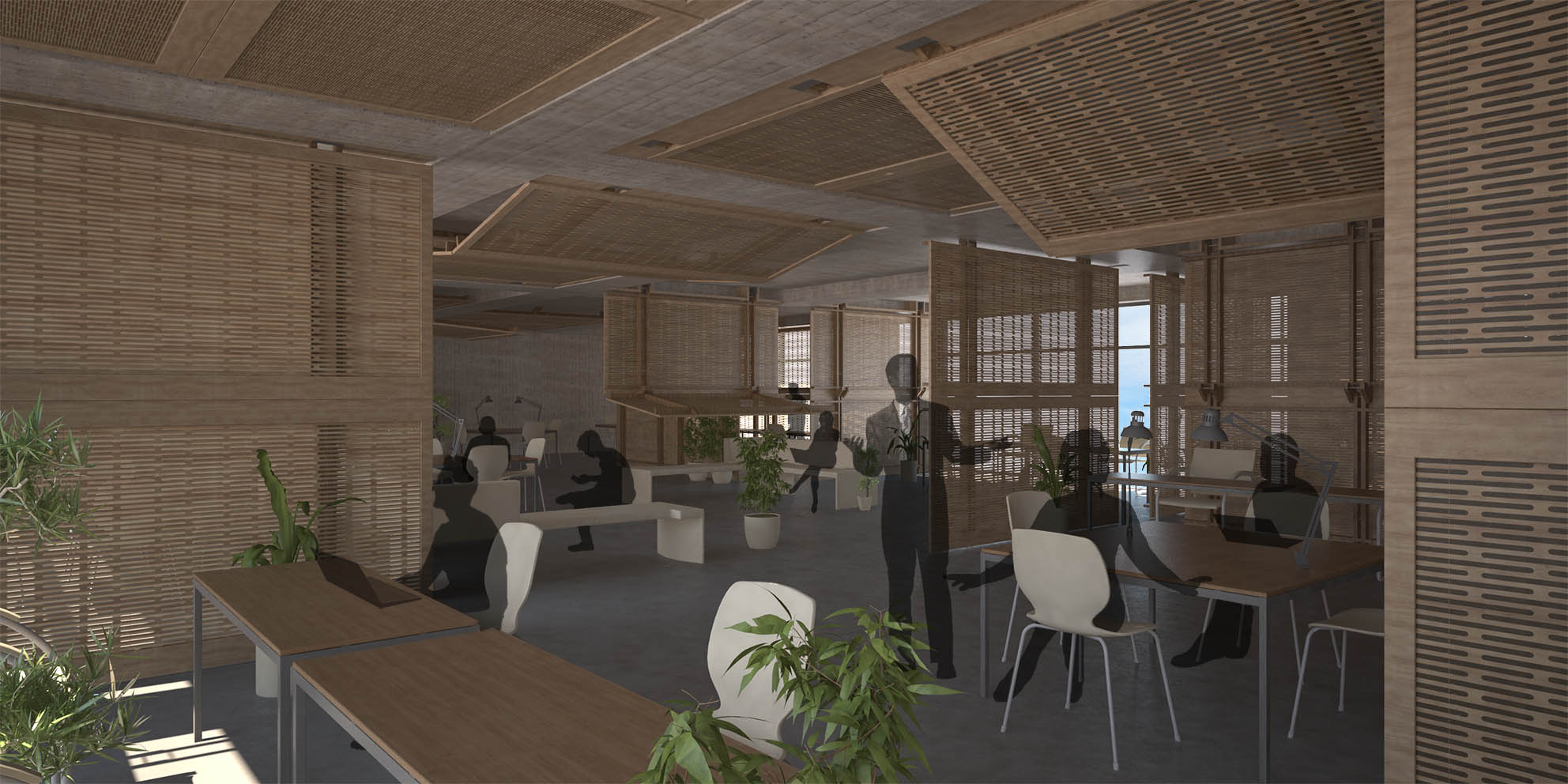
As I've mentioned, I am using this prototype as part of my diploma project for my degree in Architecture at the National Technical University of Athens. Here are some pictures from my diploma project about how thiw prototype could be used in real life in the ceiling of an open-plan office space.


Project Development
Deadline
The final presentation of my project is on the 16th of June.
Tasks to be completed
My prototype is completed and it is working relatively well. The only problem is that the servos get stuck quite often, so I need to investigate how I can fix that. Apart from that I also have to make the video and the presentation. I plan to work on all those tasks simultaneously, so that I can be sure that they will all be satisfyingly completed by the time the presentation arrives.
What has worked and what hasn't
In general I am very satisfied with how my prototype works. It is well balanced, and so it requires little force to rotate, the electronics and the wireless communication work well, and everything is integrated in a more or less coherent whole.
The only substantial problem as I mention above is that the servos get stuck sometimes because they are not strong enough. I can try to fix this by improving the balancing of the springs, but after that, I should change the servos if I want the problem to be gone completely. I don't think I will change the servos for my final project, but I discuss what I believe should be done about that in the Conclusions and further research paragraph.
Bill of materials and cost
Plywood--------------------------6 €
two motors-----------------------30€
HC-05 bluetooth module-------9€
metallic parts---------------------4€
metallic thread-------------------7€
springs---------------------------4€
acrylic----------------------------0€ (I managed to find some wonderful scraps!)
ioanduino------------------------(around) 2€
Total cost around 60 euros.
The exploration Process
In other words, how I got from being able to make almost anything, to making this final project.
This was my fab-academy calendar about the work that was relative to my final project. I go into a lot of detail which probably interests only me, but it was necessary so that I don't forget all the parts of my research.
30-April-2017
Adding the motor
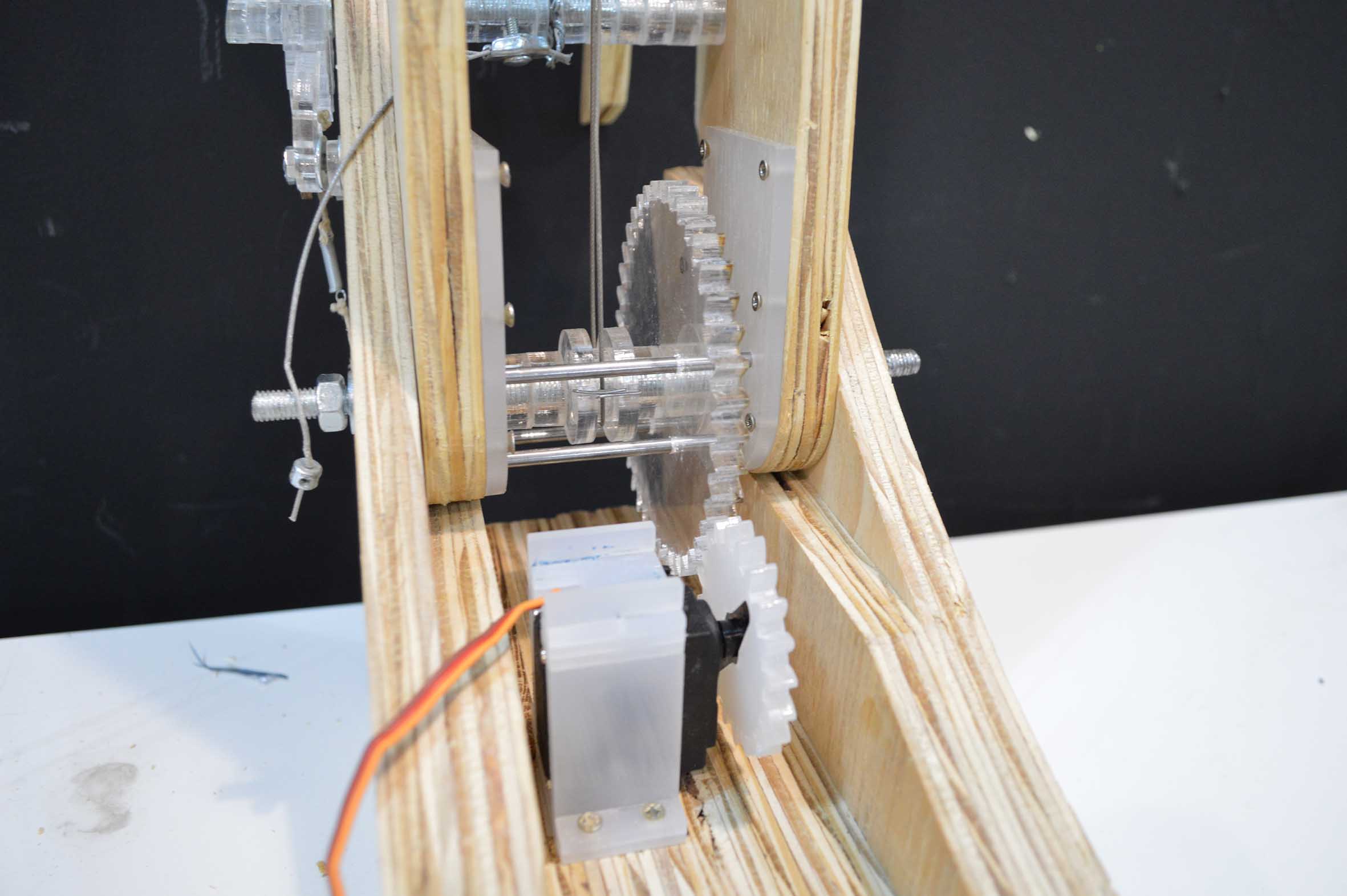
The next step was to add a motor and try to automate the movement. For the fabrication of the new pieces of this week I used mostly scraps of acrylic from the lab, and the laser to cut them. All in all, what I needed to was to find a way to attach the servo on the wooden base, and to make the gears that will move the arms.
For the gears I used the grasshopper plugin Gear, which is a very handy tool for generating gears with different radiuses that work together. I then carefully measured the motor and designed a press-fit case for it, with holes for screws so that it can be securely attached to the base.
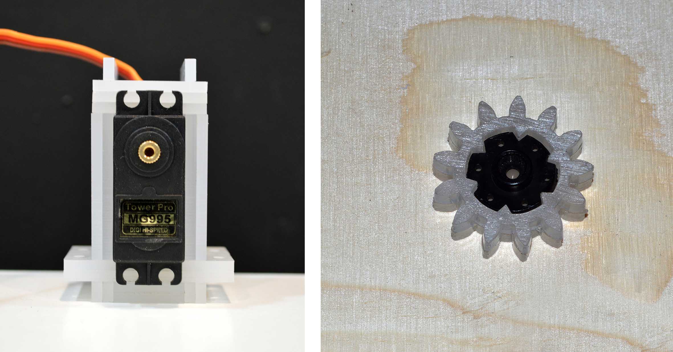
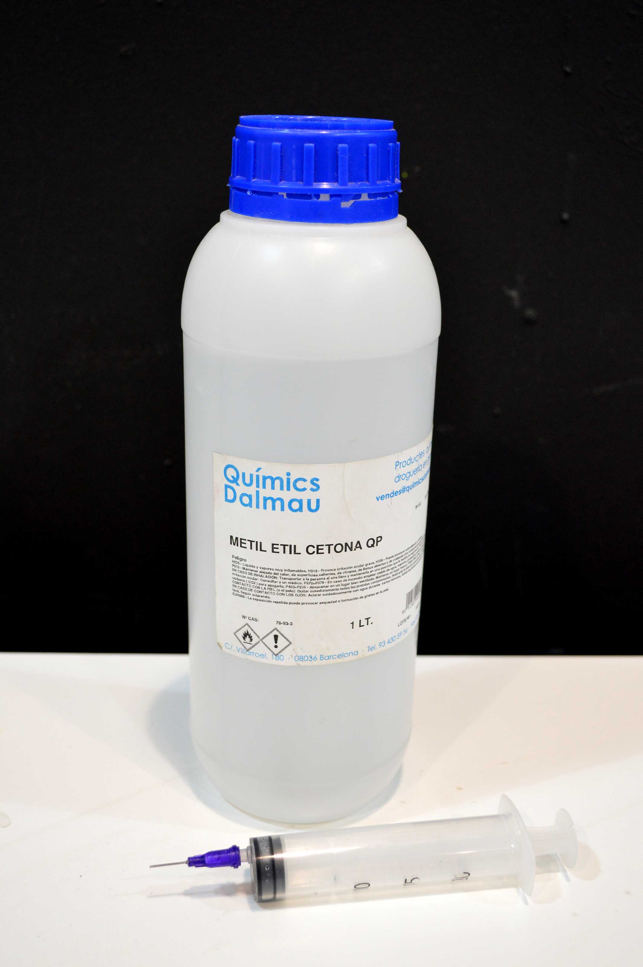
In order to glue acrylic I used “Methyl ethyl ketone (MEK)”, which gives very nice and strong connections between touching surfaces of acrylic. It is a substance that evaporates very fast and thus needs to be applied with a syringe, and always must be used in a place with good ventilation (preferably outside), as it is harmful when inhaled. Also, in order for the connection to be good, the surfaces need to perfectly touch, so sanding is necessary before putting them together, to remove small imperfections that keep the surfaces apart.
Here’s my motor with its case and its gear.
Then I also needed to reconfigure the joint of the arm, so that it can connect to the motor. For this I used 8mm acrylic to make the gear, 4mm acrylic for other necessary pieces, and a few metal bars (4mm radius).

I then placed the motor in its position, and did a few adjustments so that the gears fit perfectly.

I decided to begin by automating the movement of the lower arm alone, so I removed the upper arm. For this first test I used Arduino, and connected it to the motor and to external power.
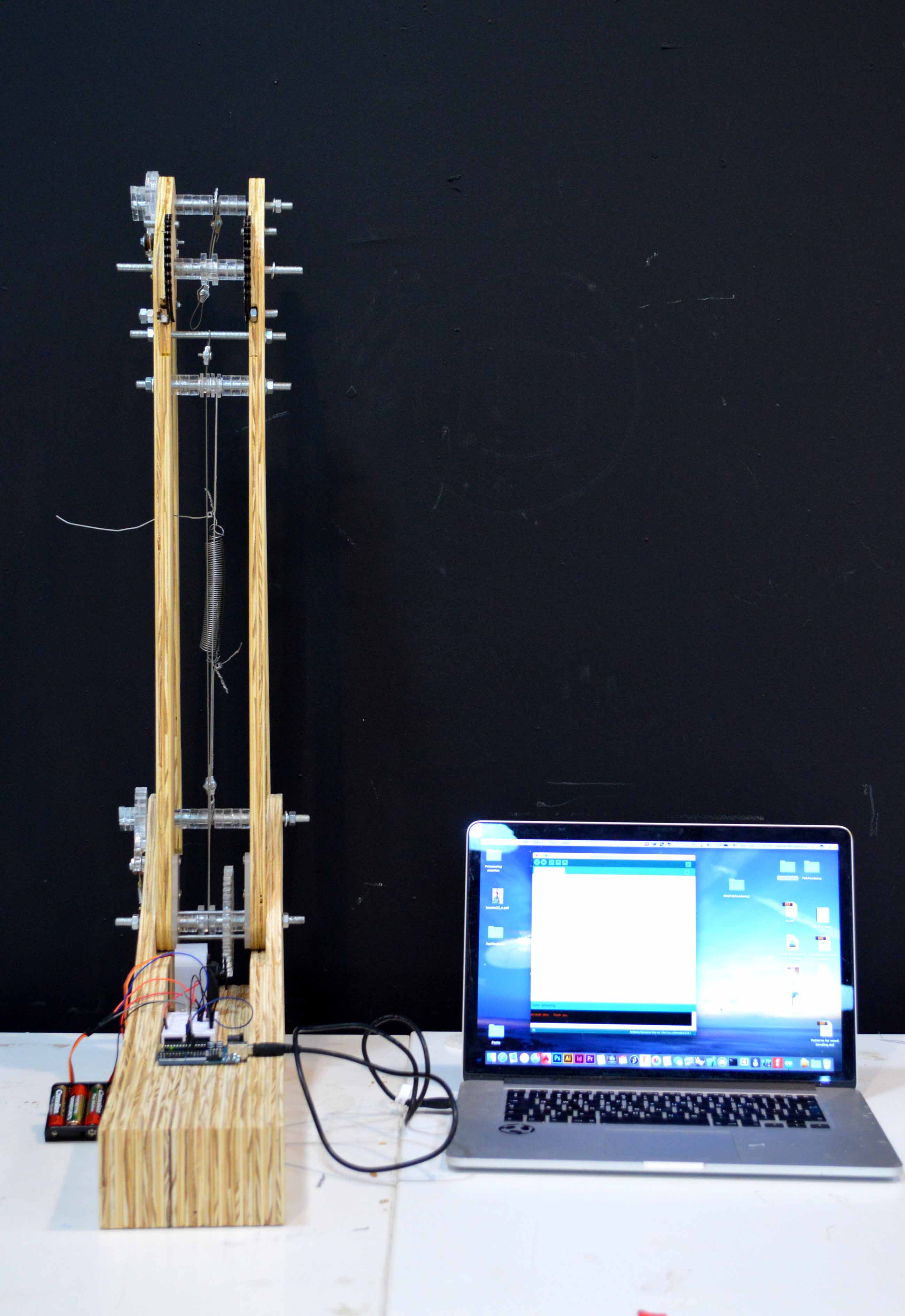
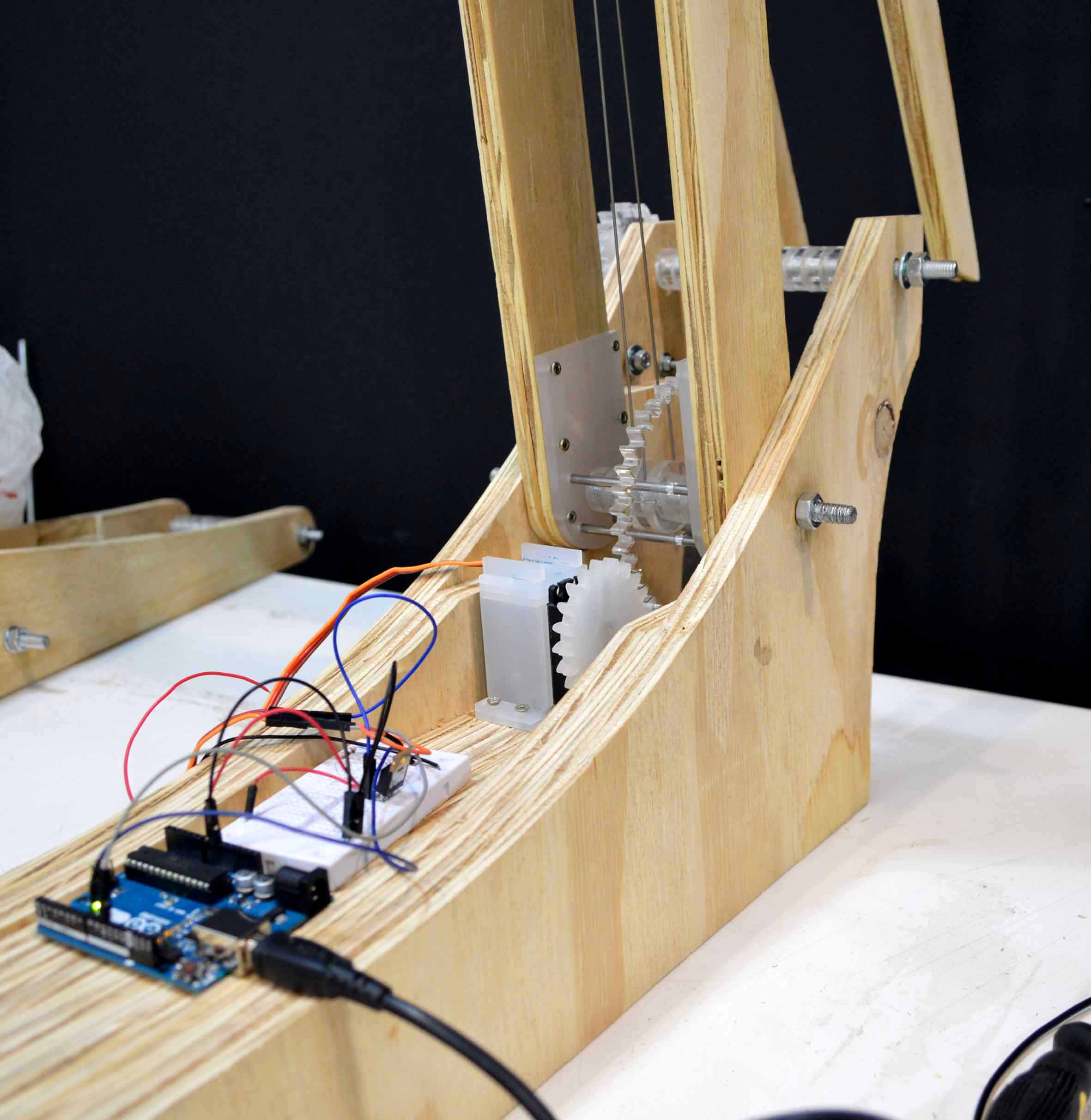
Overall the problem I encountered was that the motor was not strong enough, so it got stuck in places or moved irregularly. I had hoped that the help from the springs would be enough for a servo with torque 15kg/cm. This is an issue I must seriously think on before I make my final model.
Adding the motor (1) from Ioanna Mitropoulou on Vimeo.
Adding the motor (2) from Ioanna Mitropoulou on Vimeo.
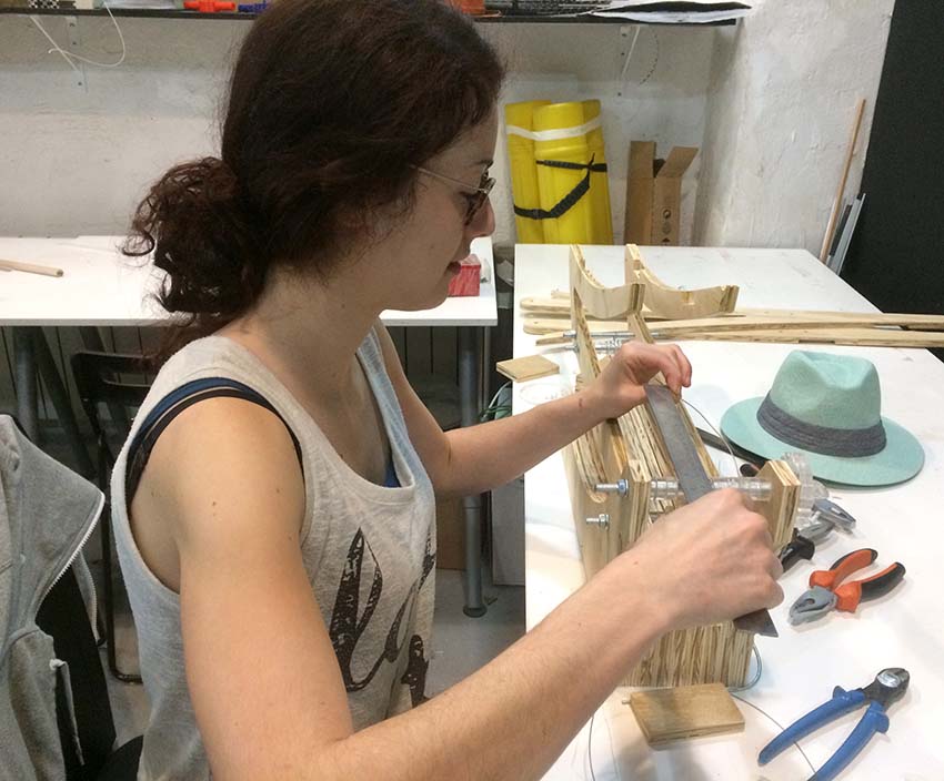
22-March-2017
During the Week 7 whose subject was large format CNC milling, we had to produce something big using the CNC, so it was the right time for me to make a bigger model.
I started with the model I had from the small experimentations, and tried to adjust it to a bigger scale, drawing knowledge from the experience acquired from the small models. Also, I decided to add a “back” on each arm, so that I can later attach surfaces on the back and test the capacity of the mechanism to carry something other than itself. Here’s the evolution and the final model.

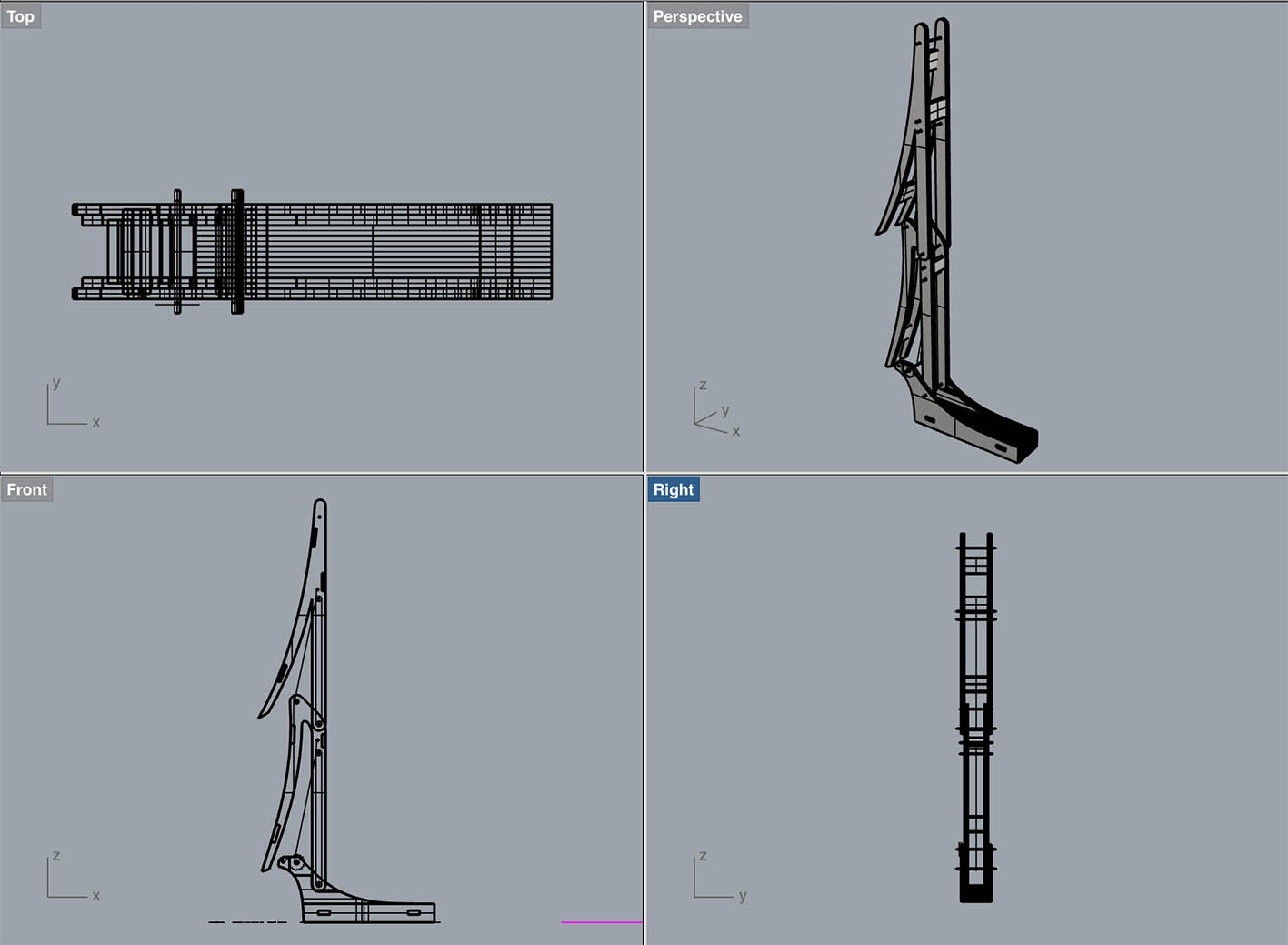
I used the RhinoCam to generate the tool path, and the Precix 11100 CNC, with a flat 6mm upcut mill as my tool.
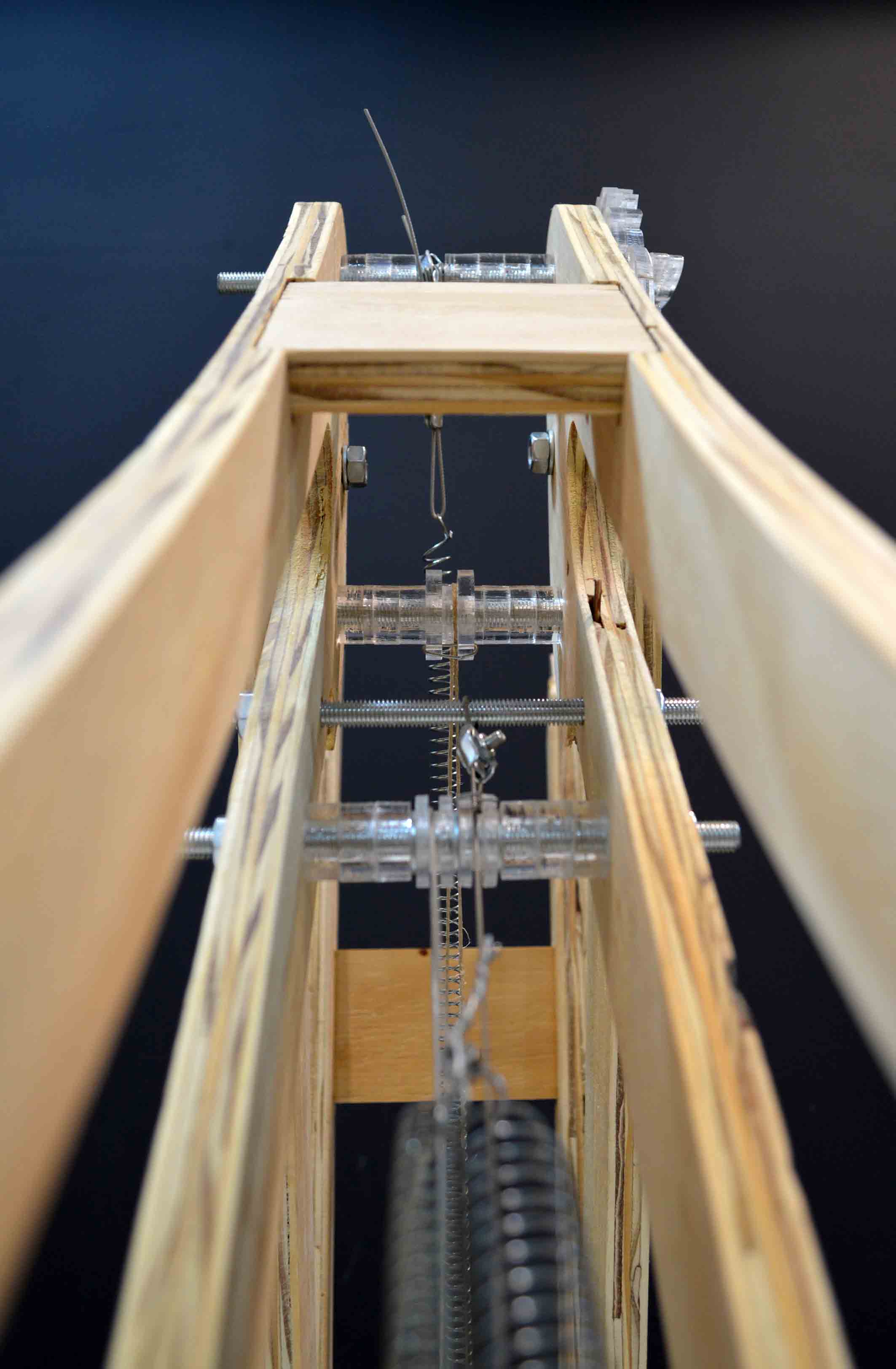
Putting together the model was not an easy nor quick process, but eventually it did come together. It took a little longer than expected, but I finally completed it. Well, "completed" is too big a word to use, as I have a lot of future additions in mind, but the part concerning the CNC seems to be over. The total height is 1.60 m and the weight is (----) kg. Plywood of 15mm thickness is the basic material (cut on the CNC), but I'm also using metal wire, acrylic (cut in the laser), metallic springs -obviously-, metallic bars, and very few screws.
Overall, the springs work to balance the mechanism, but it is not balanced in all the positions I expected it to. I'm still working on finding the correct springs, but I believe it is also a problem of the overall geometry. I am investigating what is the problem with the lower positions where it is not balanced, even though the smaller models were perfectly balanced in those positions.
Nevertheless, I'm very content with the result given the fact that it was my first model of this scale. The future additions concern mostly the surfaces that will be applied in the "back" of the arms, improvement of the rachet mechanism to make it easier to open at will, and a mechanism that is able to lock it on specific positions.


16-March-2017
Defining the spring's physical properties
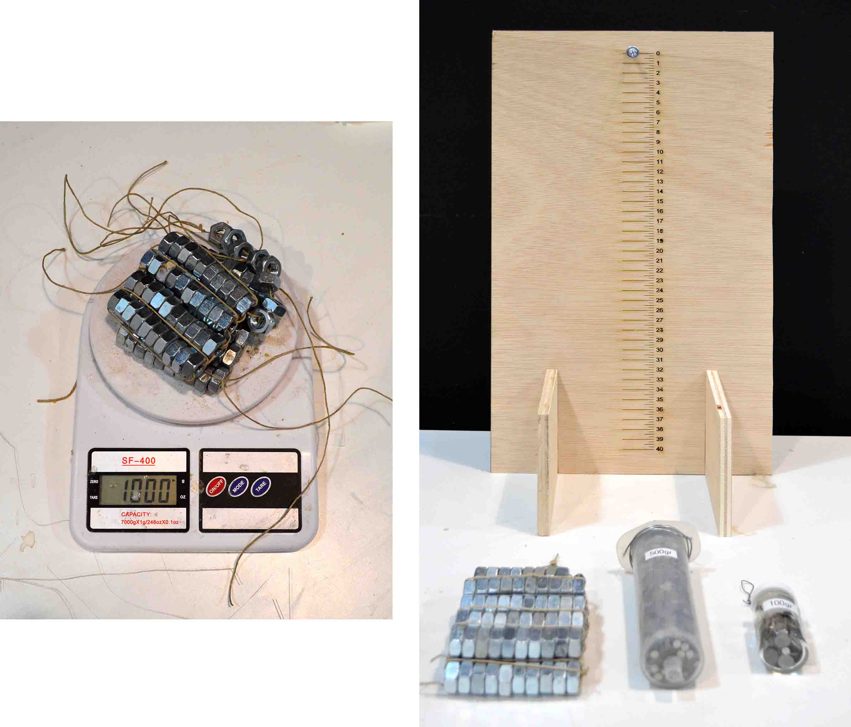
Having finally understood the maths at work on this mechanism, and with the prospect of scaling up my models, I needed a clear picture of the physical properties of my springs. For this I gathered all the springs I’ve acquired so far, and I created my own measuring scale and weights.
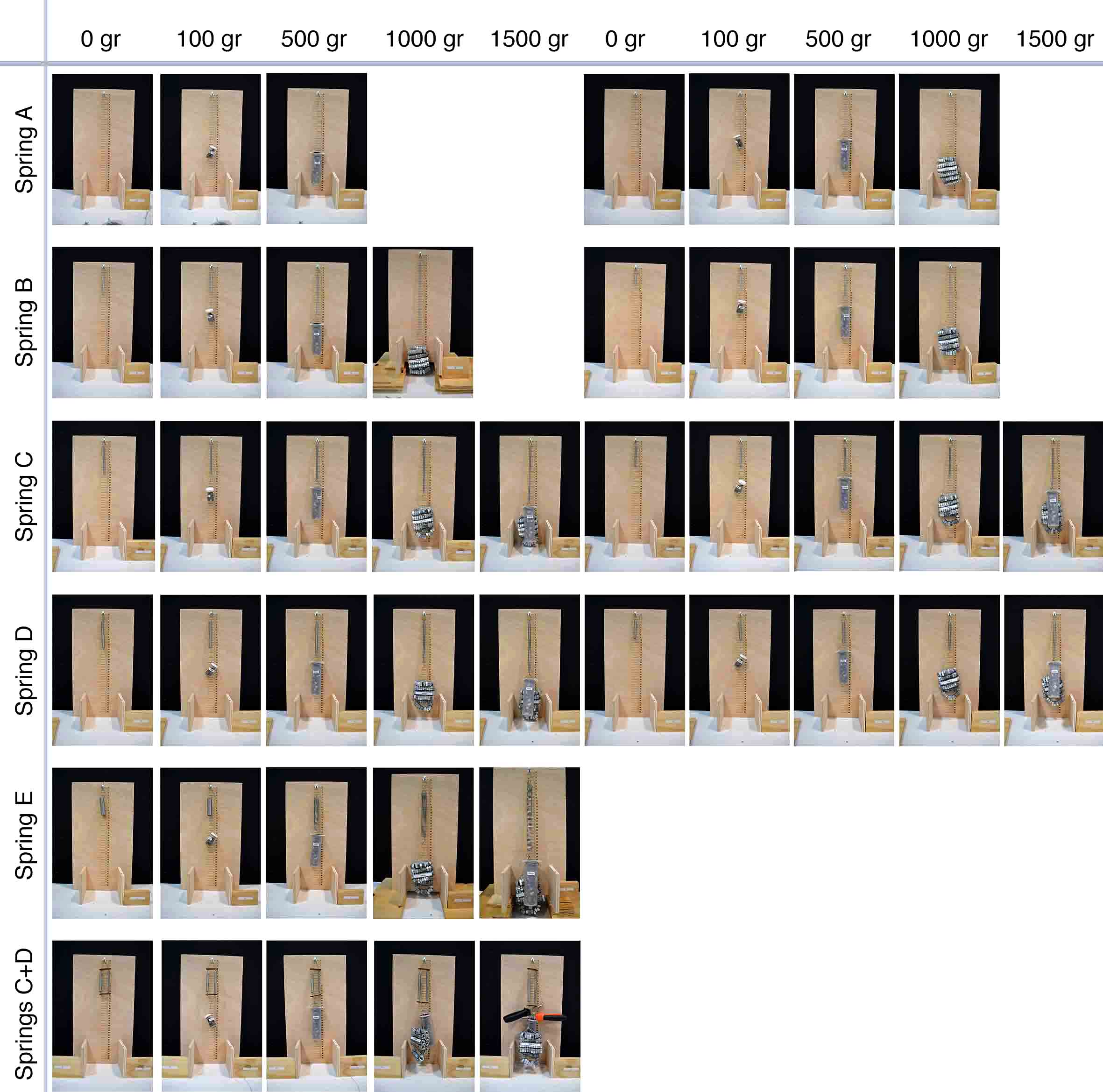
I then made multiple measurements with two different lengths for each spring, and gathered all the measurements in an excel file. This helped me calculate the average stiffness coefficient for each type of spring per unit of length.

8-March-2017
The physics behind the mechanism
Hook's law
Hooke's law, named after the 17th-century British physicist Robert Hooke, is a principle of physics that states that the force (F) needed to extend or compress a spring by some distance X is proportional to that distance. That is: F = kX, where k is a constant factor characterising the stiffness of the spring, and X is the deformation of the spring.

Potential Energy
Potential energy is the stored energy of an object, by virtue of its position relative to other objects. Potential energy is associated with conservative forces such as spring forces or the force of gravity. The action of lifting the mass is performed by an external force that works against the gravity. This work is stored in the force field as potential energy. If the external force is removed the force field acts on the body to perform the work as it moves the body back to the initial position, causing a body to fall.
Suppose a ball which mass is m, and it is in h position in height. If the acceleration of free fall is g, the weight of the ball is mg. So the total work or energy is force × displacement = mg × h = mgh
Elastic potential energy is Potential energy stored as a result of deformation of an elastic object such as a spring. It is equal to the work done to stretch the spring, which depends on the spring constant k as well as the distance stretched. According to Hooke's law, the force excerted has the form F = kx. Therefore the work done to stretch the spring a distance x is W=1/2kx^2
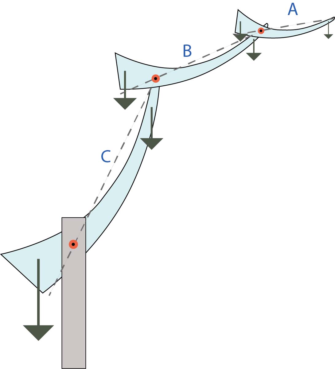
The balanced system
A balanced system is designed such that a constant potential energy is established throughout its range of motion, given that the mass remains stable. The constant potential energy removes any preferred position of the system and thus, the system can be moved easily regardless of its weight without depending on actuators.
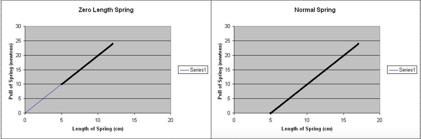
For the following equations the springs are considered to be zero-free-length springs. These are ideal springs are pre-tensioned to such a degree that their tension is proportional to their length, instead of their elongation. In other words, the zero free length spring would exert zero force if it had zero length. In a line graph of the spring's force versus its length, the line passes through the origin, while in normal springs it is displaced according to their minimum length.
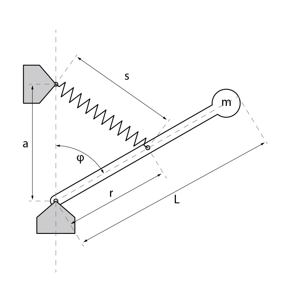
Up = Um +Us =mgLcosφ + 1/2ks^2 (1)
And according to the Law of cosines
s^2 = a^2 +r^2 −2ar cosφ (2)
For a mechanism to be in equilibrium, the potential energy must be stable, and therefore its rate of change is 0.
DU/Dt=−mgLsinφ+karsinφ=0 (3)
Consequently the angle φ is crossed out of the equation, and the following condition for static balancing arises:
mgL = akr (4)
And basically that is all there is to be said. If this condition is met, the mechanism is in equilibrium for any configuration in its workspace.
This clearly shows the possibilities for adjusting the balancing properties: by varying a or r (the position of the attachment of the spring), k (constant factor that characterises the stiffness of the spring), L (the length of the arm), or m (the mass of the arm), different balanced configurations can be achieved.
When examining a balanced system with two degrees of freedom (in our case two arms), then the same equations apply to each arm separately, as long as the mass of the elements above the element examined is taken into consideration.
In reality it is very difficult to manufacture zero free length springs, so normal ones are used in my models with a wire-and-pulley construction as shown in Fig.1. However, an error is introduced by the pulley because the wrap angle of the wire (β) will depend on the position of the weight arm (φ). Consequently the wire length is not always exactly proportional to the spring elongation (and thus force) required for exact balancing. Some optimisation is possible by reducing the size of the pulley and carefully positioning it horizontally to reduce the error, but the balancing still remains inexact. This problem can be solved by introducing (at least) two additional pulleys. The three pulley solution, shown in Fig 2 and 3, ensures that the same amount of wire is always wrapped around the pulleys regardless of the position of the arm, and therefore the elongation of the wire will be exactly proportional to the distance between the axes of the pulleys at all times.

References
R Barents, M Schenk, W D van Dorsser, B M. Wisse, 2009, "Spring to spring balancing as energy-free adjustment method in gravity equilibrators", Proceedings of the ASME 2009 International Design Engineering Technical Conferences
J Herder, "Energy-free Systems", University of Delft, Netherlands
M J French, M B Widden, 2000, "The spring-and-lever balancing mechanism, George Carwardine and the Anglepoise lamp", Lancaster University, UK
Zero length spring
23-February-2017
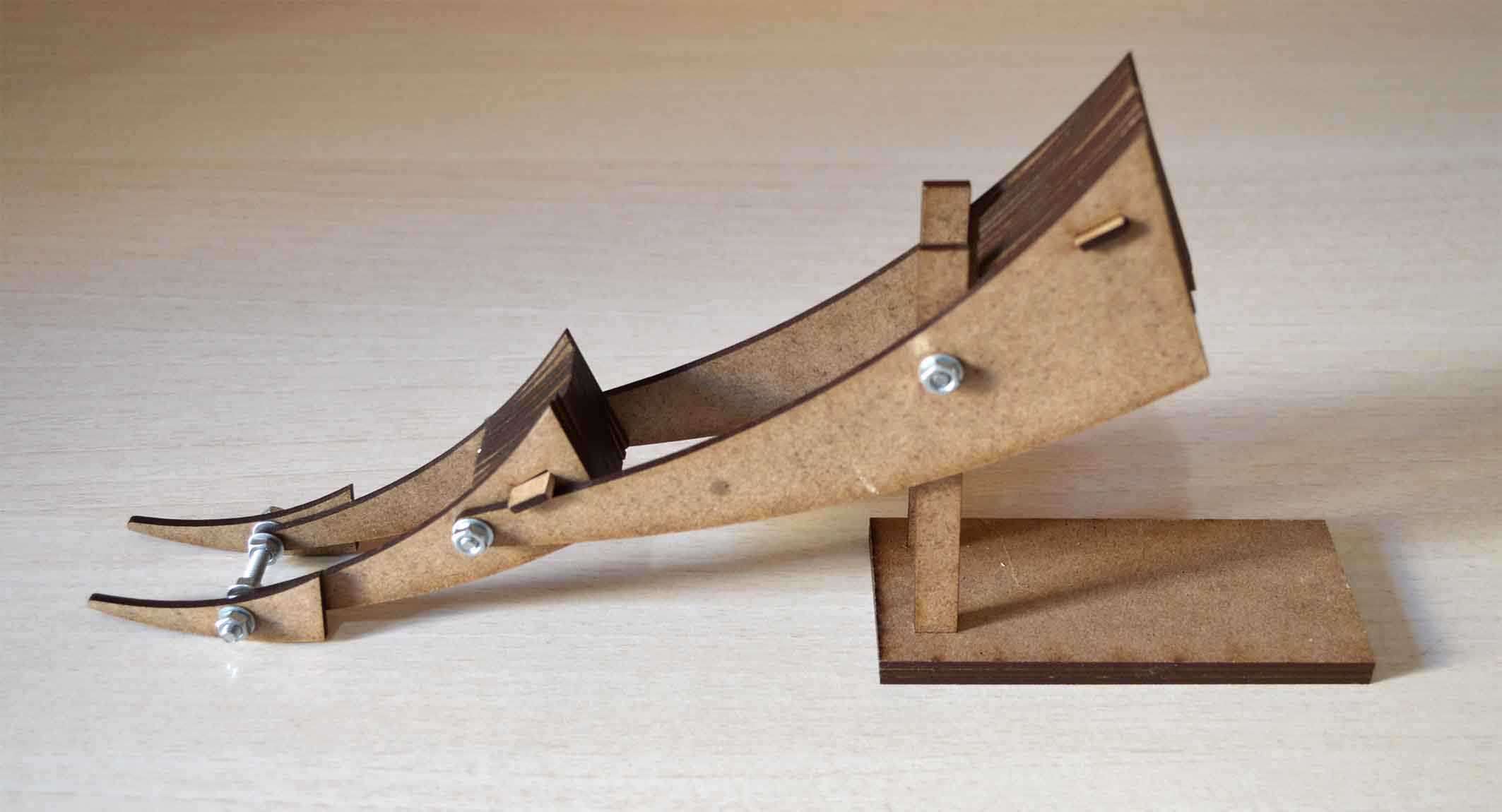
Working with springs was a wonderful idea which helped me advance my concept a lot. I started with a reference of a balanced-arm lamp mechanism with tension springs within the arms. I translated it into my project's geometry using Rhino.

From this model I learnt A LOT. First of all, it actually works, and it is quite reliable when the tension in the springs is properly adjusted. I didn’t use any glue in my model, so that I was able to put it together and apart as many times as I needed while I was experimenting with different configurations. This process was very beneficial so that I could understand how it works, and identify my next steps.
Tension is a key word. Probably the most important parameter in the model. The tension that the spring needs to have so that the arm can be balanced at all positions depends on the weight of this arm and of everything that is above it. This means that if an extra weight is added, then the structure is no longer in balance. In order for it to come again in balance the tension of all its springs must be modified.
This led me to a long research about how I can have a way to adjust the tension, which I had not foreseen and so it was really difficult in this model. I tried several ways such as different tensioners or metallic rings. Overall this is the first next step: the addition of a mechanism that helps adjusting the tension.

Friction is a great friend. In fact it is only thanks to friction that all this is possible. The spring counteracts the weight so that the arm is free to move, and it is thanks to friction that it stays in place. When you move the arm, you only have to overcome this friction with your strength, and it doesn’t matter what is the actual weight of the arm you are moving. However not all friction is good, in certain parts it is better to be minimised, while in others it should be kept higher, yet not too high. I identified those empirically.
My next step here is to change slightly the configuration so that it increases the "good" friction, and decreases the "bad" one.
Other improvements needed:
Better balance
Larger ground counterweight
16-February-2017
Cutting the model on the laser was not very difficult. I connected the pieces either by geometrical configuration or by metallic hinges. I am not a big fun of glue and wanted the model to be easily demountable. What is more, i needed counterweights that would allow me to add weight or subtract it if necessary. Everything worked out well, except from the fact that my perfectly balanced 3d model was not at all balanced in reality.
I started making adjustments on the materials and on the counterweights to achieve balance. And here it is when I finally got it to work. It can be balanced in any position, but it’s not very stable.


Disheartened by this conclusion I set off to find different ways of using counterweights that would be easier to construct, would require less material and be more robust. And as it always happens, everything I try to ‘invent’ has been invented centuries ago, and all I have to do is find it and understand it. In this case, one possible answer was in front of my eyes. Literally.
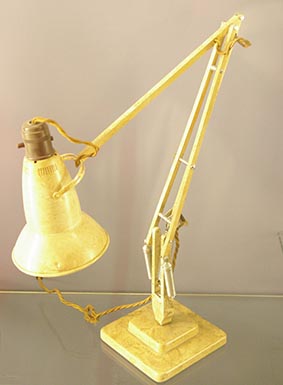
(This lamp is not really mine, its a collectible model from 1935, but I also have one)
The Anglepoise lamp is a balanced-arm lamp designed in 1932 by British designer George Carwardine, that uses spring forces to balance the elements. The result is a modular structure whose elements are “floating”: they can be moved very easily and are balanced in every position. I believe that maybe I could use the same logic for my project.
5-February-2017
During the 2nd week I explored a few mechanisms that could be used for my final project, through modelling and animating them in parametric software. The one that interests me most is the counterweights.
As I also mention in the week’s assignment, using counterweights for moving parts is a very simple yet really powerful concept that is often used when there is need for very smooth movement or for moving heavy parts without requiring a lot of strength. The basic idea is that it is much easier to move one element if you can provide a counterweight through a smart geometrical configuration or by using elements such as levers or ropes. The main disadvantage of this strategy is that it almost doubles the weight of the assembly.
This mechanism has also a lot of applications in architecture both on its own and combined with other mechanisms. It is very efficient for moving platforms, surfaces and heavy objects. The application that interests me for the final project is an opening roof.
This is what my first grasshopper looks like, and after that there’s a small diagram of the idea.

Improving the Grasshopper definition was a little tricky. Here’s why. To calculate the centre of mass for each rotation I needed to start from the smallest piece that is on the top, and then for every piece calculate the centre point by adding its own weight plus the weight of everything above it (always taking into consideration the distances). However to calculate the rotation of the pieces and make it parametric I had to start from the biggest element in the bottom because it is the only one that is anchored to a stable point. And then calculate the rotation of each piece adding to the rotation of the piece right under it. The problem begins when the rotation requires changes in the geometry, and thus the centre of mass and rotation. Changing the part of the algorithm that produced an outcome based on this outcome which by its turn changes the part again.
In other words, in the grasshopper definition I had two opposites “workflows” that gave feedback to, and mutually changed each other in a way that resembles a recursive algorithm. I had to connect the end of the algorithm with its beginning. I did come up with a few solutions so that I could proceed to make my first model, but the definition still has many problems. It’ll do for now though, because I should start making my first model to see how it works.
.jpg)
.jpg)
30-January-2017
Not having a clear picture of what I want my final project to be, I will use this space as a brainstorming area where I can write my thoughts until I arrive on an exact concept for my final project.
I am interested in kinetic objects of daily use, in other worlds, objects that can transform their state to serve multiple purposes. Examples of such objects have always been around us, from very simple ones, such as doors, windows or folding tables and chairs, to more advanced ones, such as elevators, responsive facades or opening roofs.
What is usually required for such objects is a geometry that can be transformed so as to allow the objects to stabilise itself in two (or more) states/ positions of equilibrium, and a mechanism that allows the transition between those positions.
The usual approach to such problems is to put together various high-performance parts, that are based on actuators (usually the user’s strength or motors) so as to convert the actuator’s movement into the movement of the parts of the object and achieve the change of its state.
Although this approach works well, it has some disadvantages. When for example we rely on motors, the performance of the mechanism can variate based on the performance of those motors. In other words, the overall performance of a system varies according to the performance of individual parts, and the result is a design that is dependent on its parts. As a result costs can increase and the mechanism can become very expensive even when it is being built to perform a simple action.
Another approach which could lead to higher performance, lower cost mechanisms and energy savings would be to consider the design of the mechanism as one whole, and come up with smart geometrical configurations that are designed and balanced so as to alter their state naturally without being entirely based on the force of the actuator. In other words, by predetermining the function of the object, and giving it a smart geometry that helps it balance itself in those positions, more rational and beneficial movement can be achieved. What is more those mechanisms do not rely on increasing the performance of the parts themselves, but rather on their overall configuration.
In truth, many mechanisms around us fall indeed into the second category, having smart geometrical configurations that allow them to optimise their function. Take the bicycle for example, a human-powered, pedal-driven, single-track vehicle, with two wheels. The actuator makes but a small movement with his legs on the pedals, and it is translated to a long distance with the movement of the wheels. Its mechanism, designed specifically for the purpose of fast movement, allows it to optimise its function without requiring great strength from the actuator.
However, unlike those mechanisms, architectural elements are usually either static, either passively kinetic elements. The usual door, window or drawer do not take advantage of any smart geometrical configuration, and the only focus on their design is the optimisation of their hinges, instead of the element as a whole.
I would like to focus my research on designing configurations (call them architectural elements, furniture, or simply objects) that manifest some sort of movement using original mechanisms and sensor technology if possible, without relying entirely on actuators.
Here's some references to get me started
Evolution doors