10th Week, Output devices
This week we focused on learning to control output devices, such as LEDs, motors, speakers etc. The assignment was to add an output device to a microcontroller board we designed. and program it to do something.
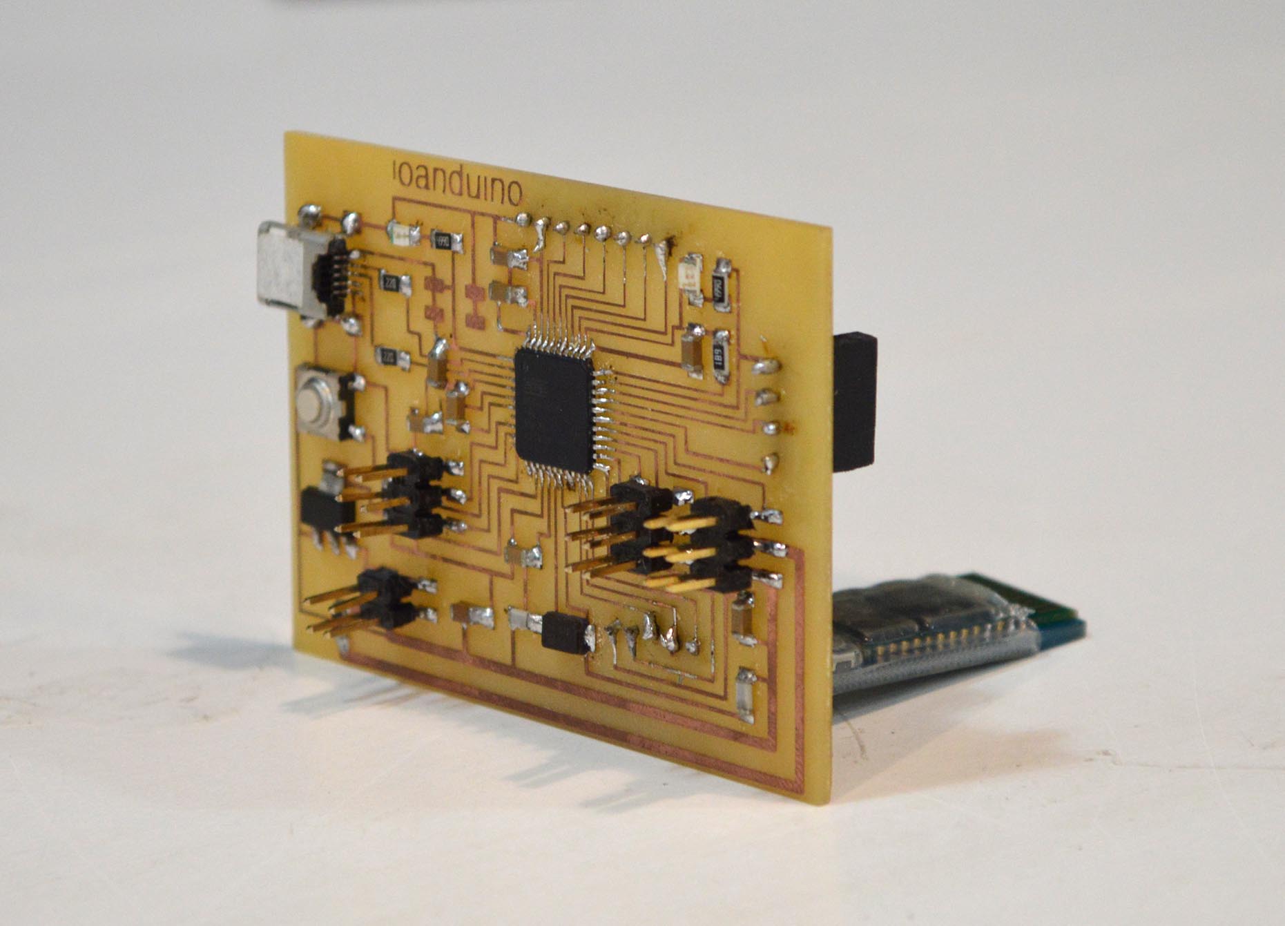
I decided to work on the board that will control the motors in my final project, in which I am making a prototype of a spring-balanced opening roof. The name of this board is ioan-duino.
Designing the board
What is the ioanduino?

The ioanduino is a board I designed for the needs of my final project. It is inspired from the Xavduino, which was in its turn inspired by the arduino Leonardo, a different version of arduino from the fabAcademy archives. The ioanduino is a simpler edition of an arduino.
The requirements of my final project are the following:
-two servos that run at 8.4V and 1.5A to open and close the roof
-a bluetooth module (5V on VCC, 3.3V on RX and TX) to communicate with the ioanduino via a phone
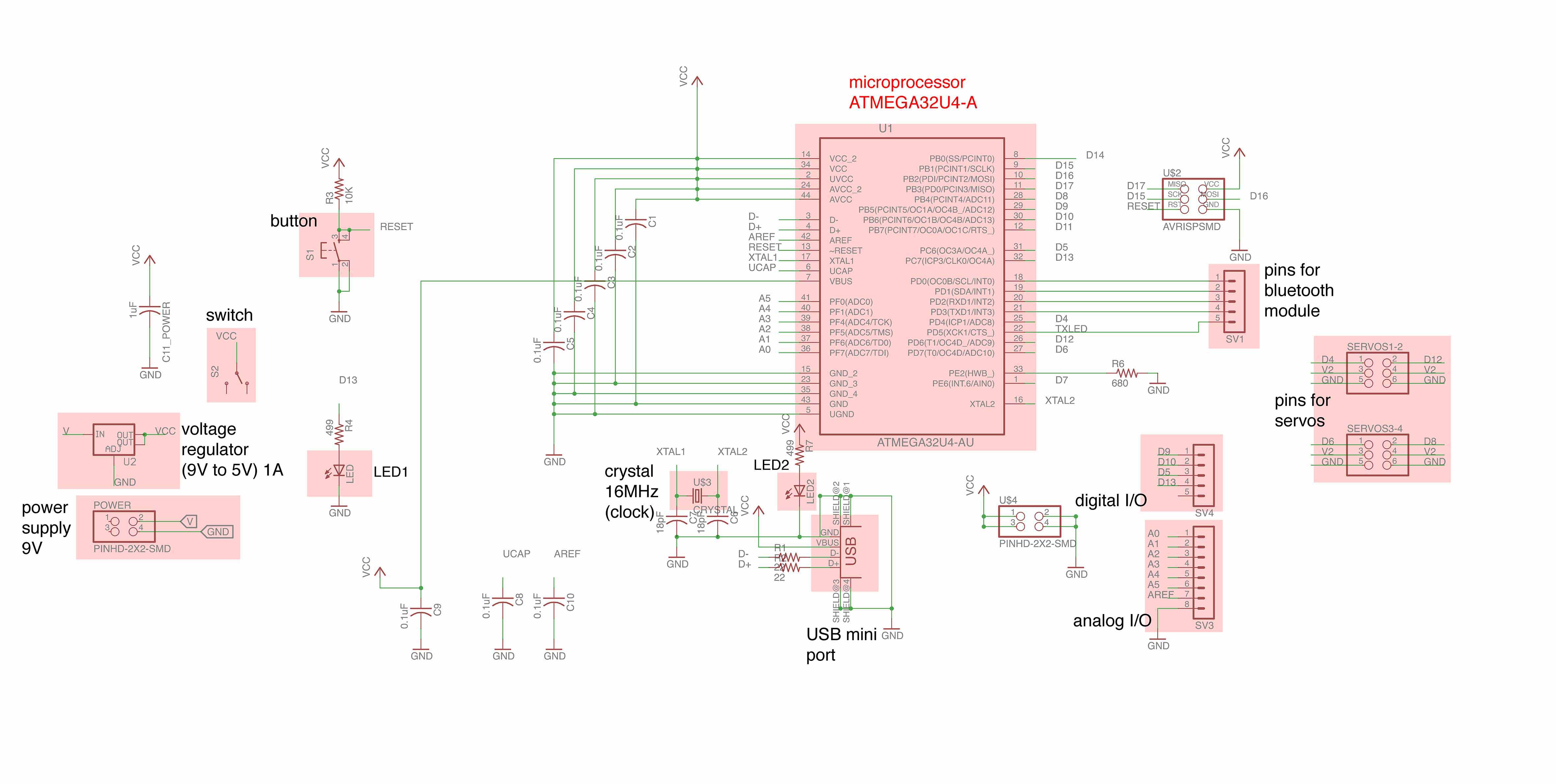
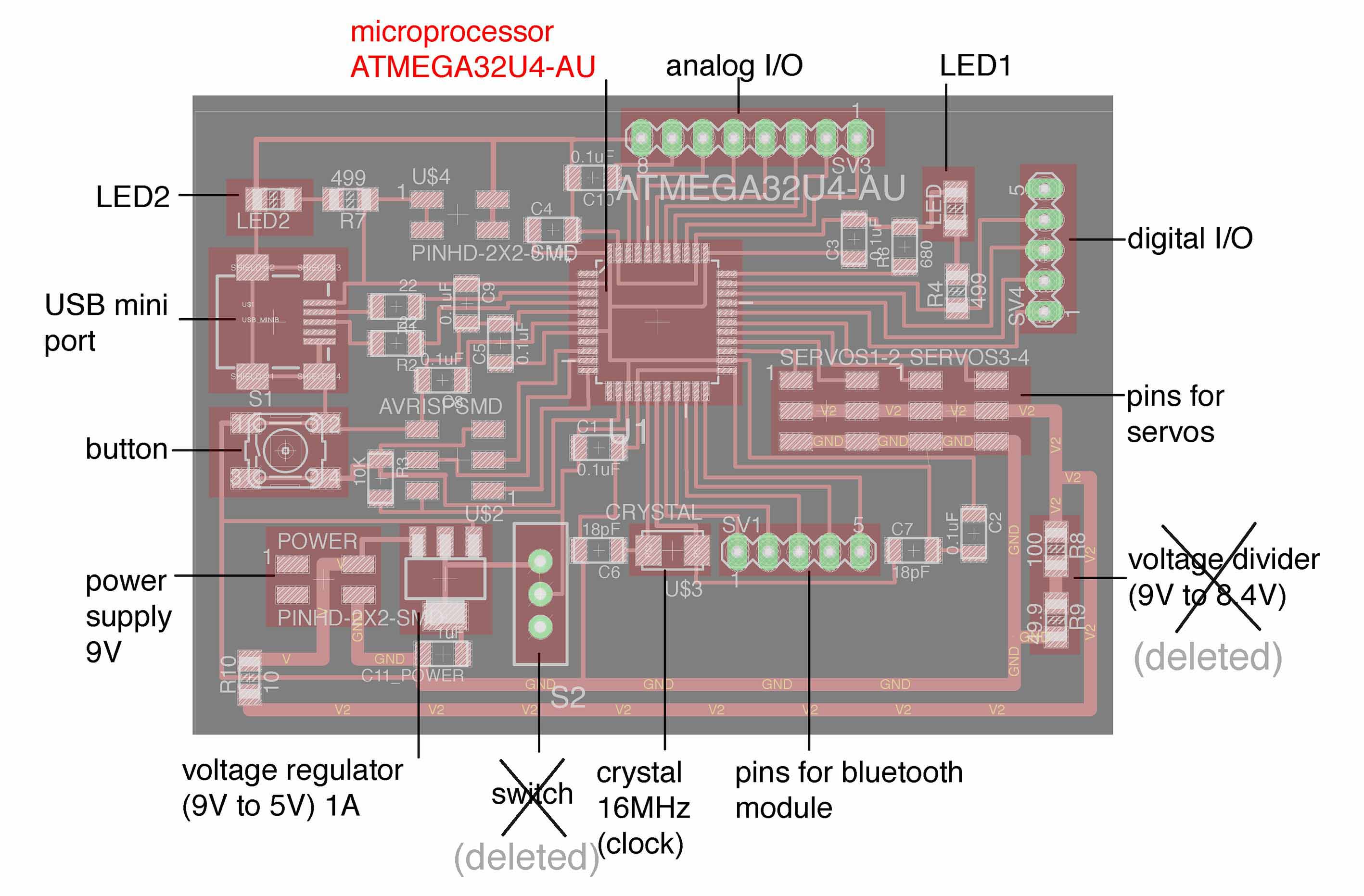
As a result, on the board I put specific pins for those components so that they could be easily connected and have the necessary voltage and amperage. In order to make the board a little more generic in case I change my mind on how I plan to use it, I added pins for 4 servos instead of two, and some digital I/O and analog I/O.
The core of the PCB is the aTmega32U4-AU.
I decided to use this microchip instead of the atTiny44 which I had been experimenting with until now because I want my servos to be controlled via a portable device using bluetooth communication. The memory of the atTiny was barely enough to store the bluetooth libraries of the arduino language, and so I wasn’t sure if I would have enough space to store my program as well. As a result I chose the aTmega32U4-AU which has the following characteristics.
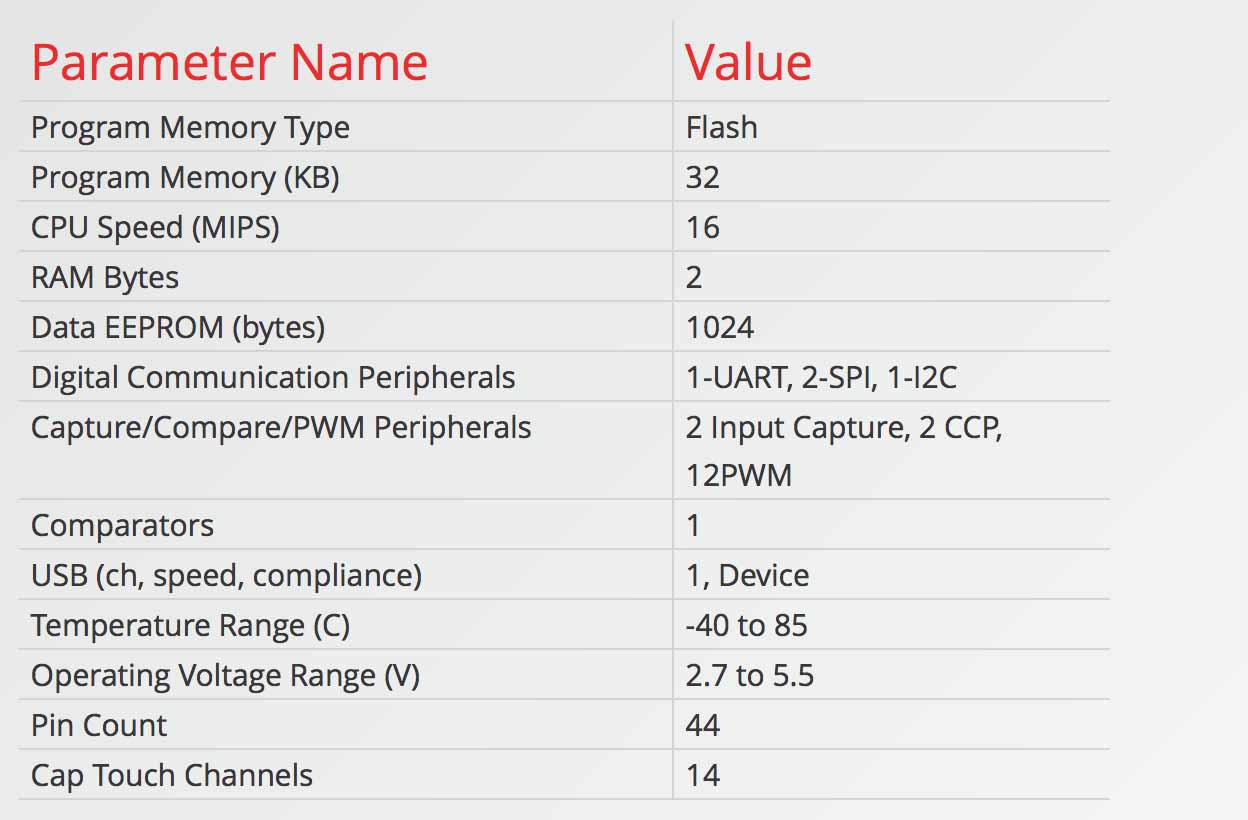
One of the advantages of this microchip, apart from its 44 pins (which allows for a lot of inputs and outputs), is that it does not require an FTDI for communication with USB because it is already incorporated inside, so it can be connected (almost) directly to a USB tiny port. The aTmega32U4-AU datasheet can be downloaded here.
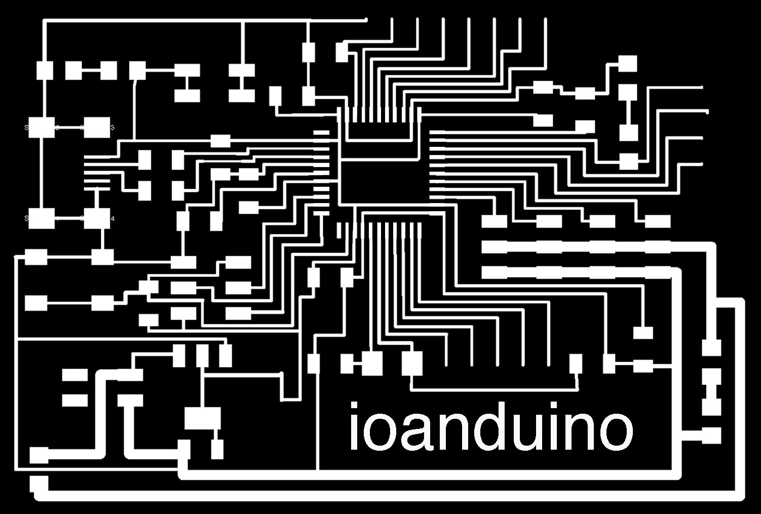
I used Eagle to design the board. In the following images you can see the different parts of my board both in schematic and in board.
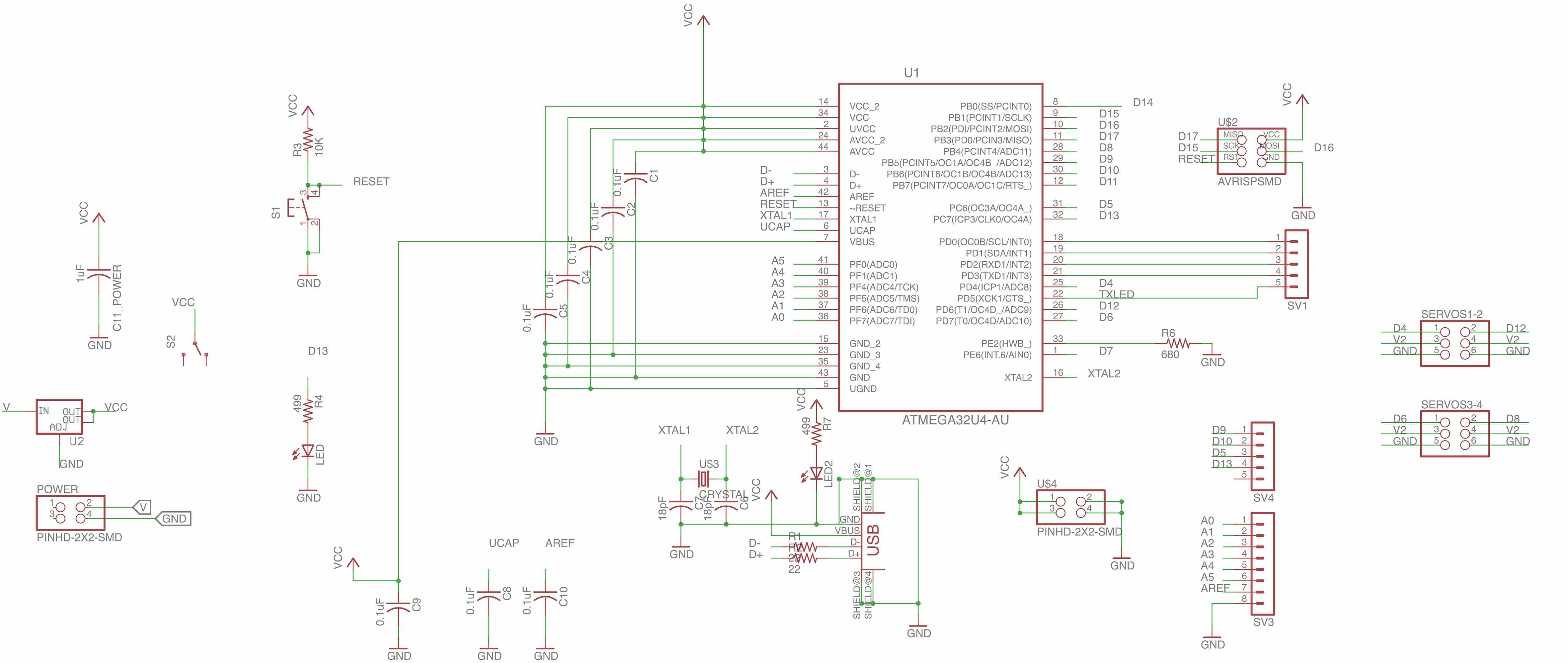
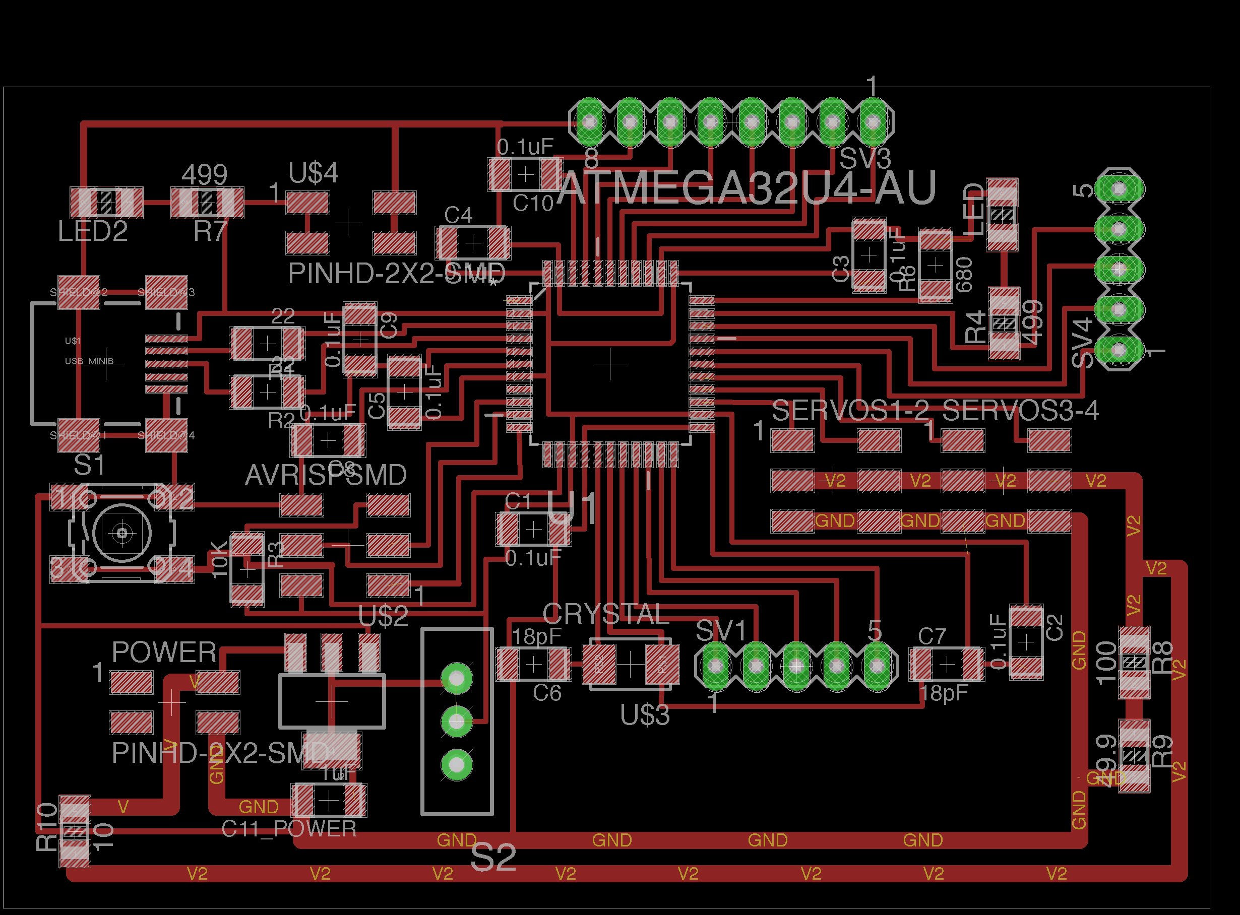
Here you can download the board.png, schematic.png, traces.png, schematic (eagle file), and the board (eagle file).
Fabrication process
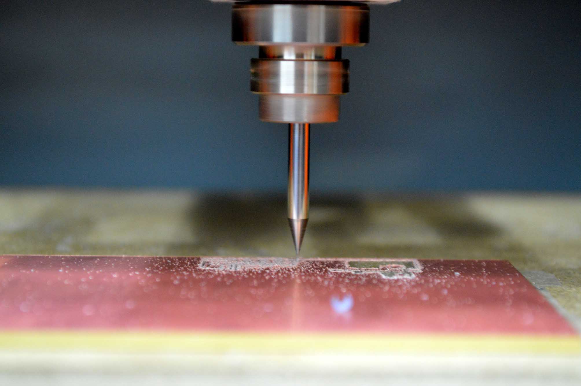
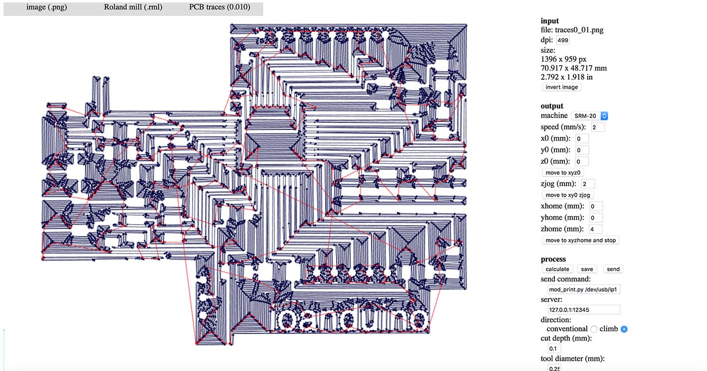
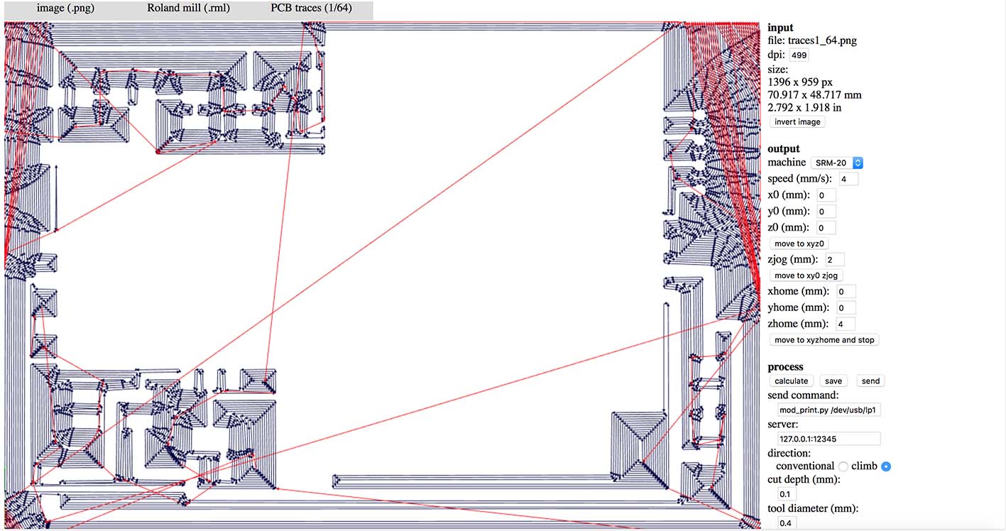
The traces were exported from Eagle and with the help from fabmodules.org the tool path was calculated. I have very thin lines on the board, so I used the 0.01 tool for the difficult parts (not without casualties), and the 1/64 for the rest of the board.
0.01 tool
1/64 tool
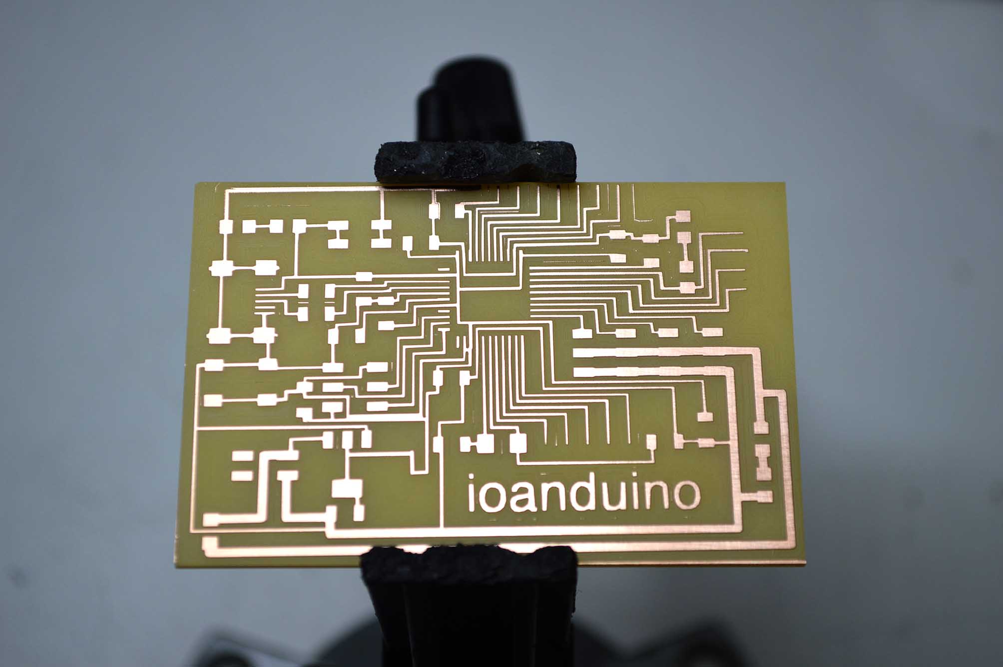
When the milling finished I cleaned the board, and I was ready for soldering.
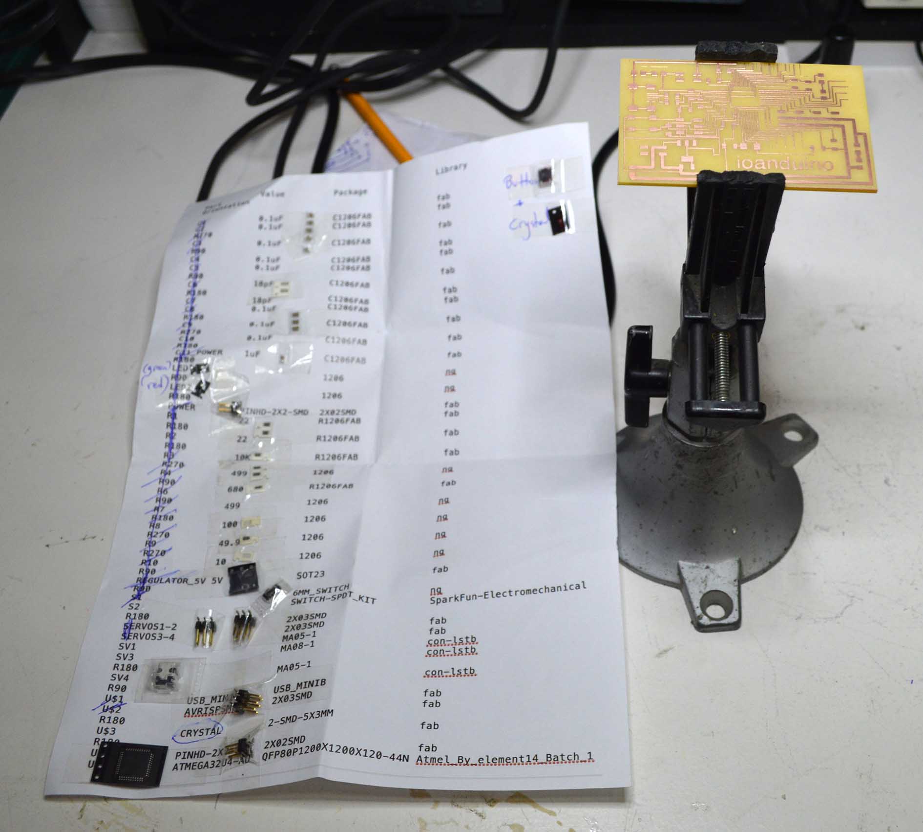
I always start the soldering by puting together all the components I will need, and attaching them on the list of parts that I have exported from Eagle.
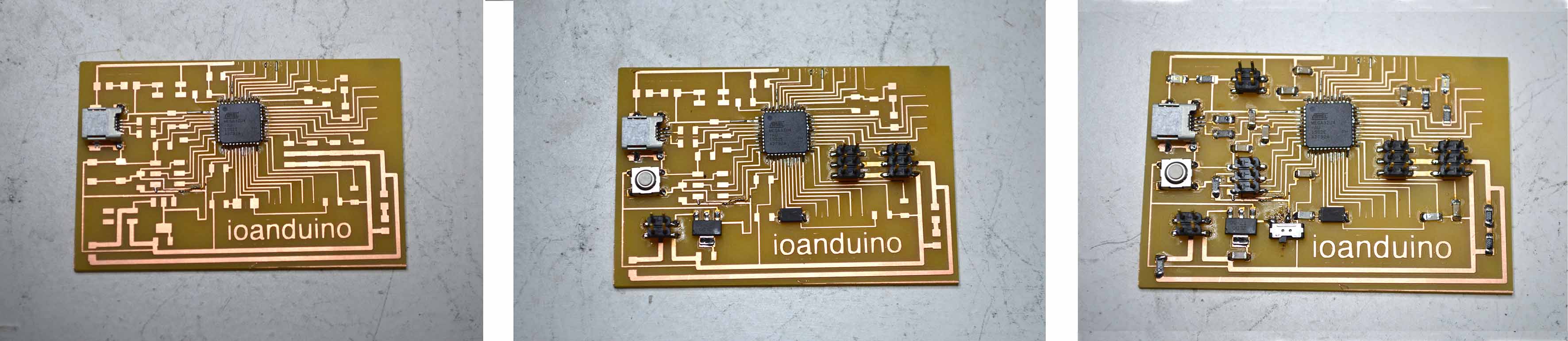
And finally, here it is. A couple of general I/O pins do not work because of bad soldering, but fortunately all the vital pins I need seem to be all right.
Programming the ioanduino
The next step was to program and test the board. I decided to use the Arduino IDE, because it is easier, and this board already has had enough difficulty. There’s a great tutorial in the FabAcademy archives, on how to prepare and program a new PCB from the 8th week (embedded programming) using the arduino IDE.
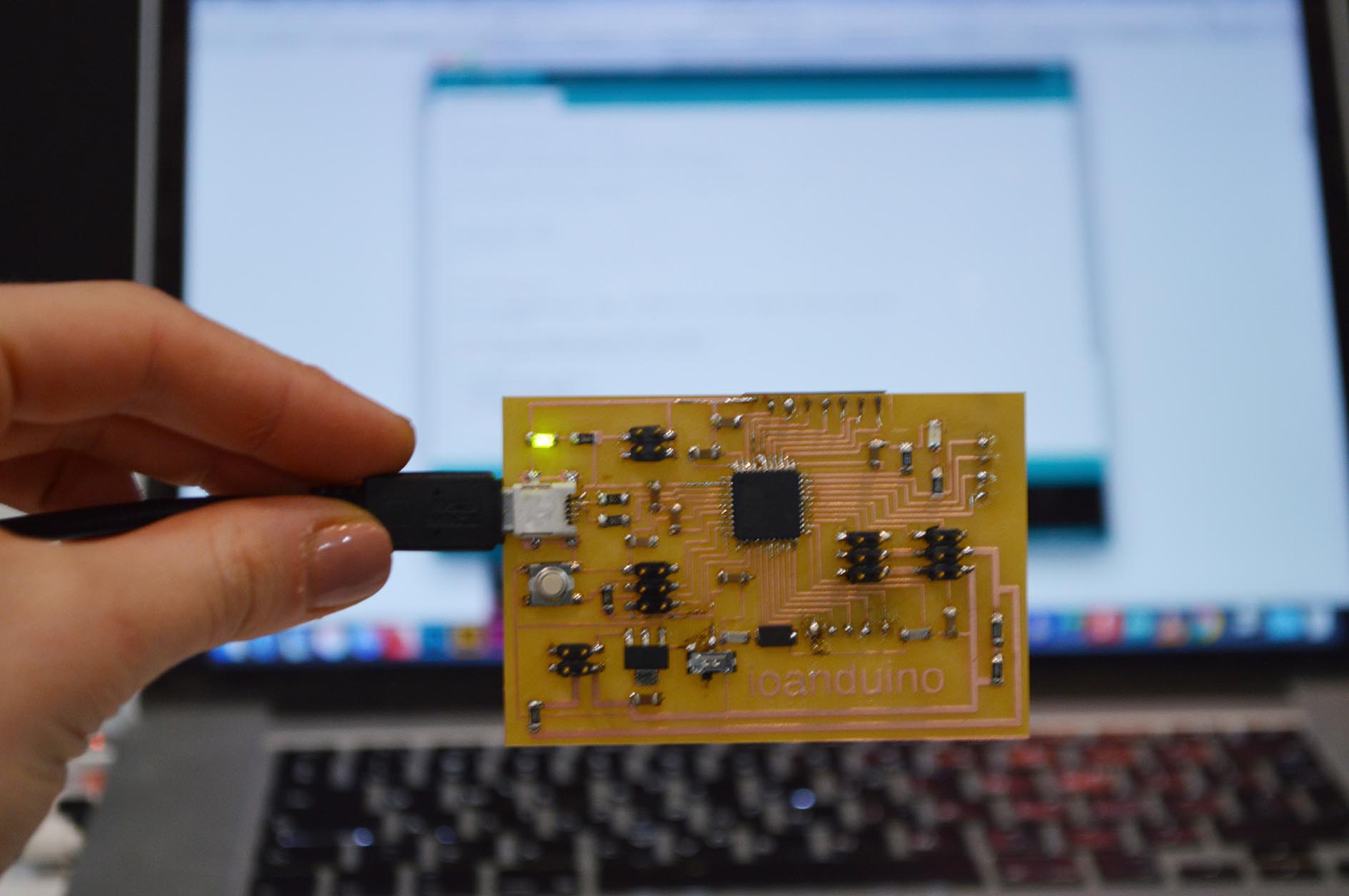
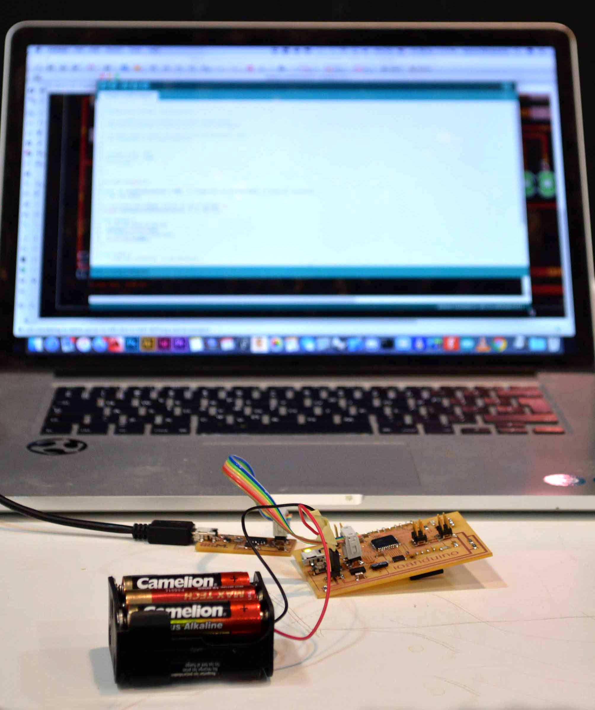
At first, I connected my board with my computer using the USB tiny port, and to my delight, it showed the first signs of working: the green led was on.
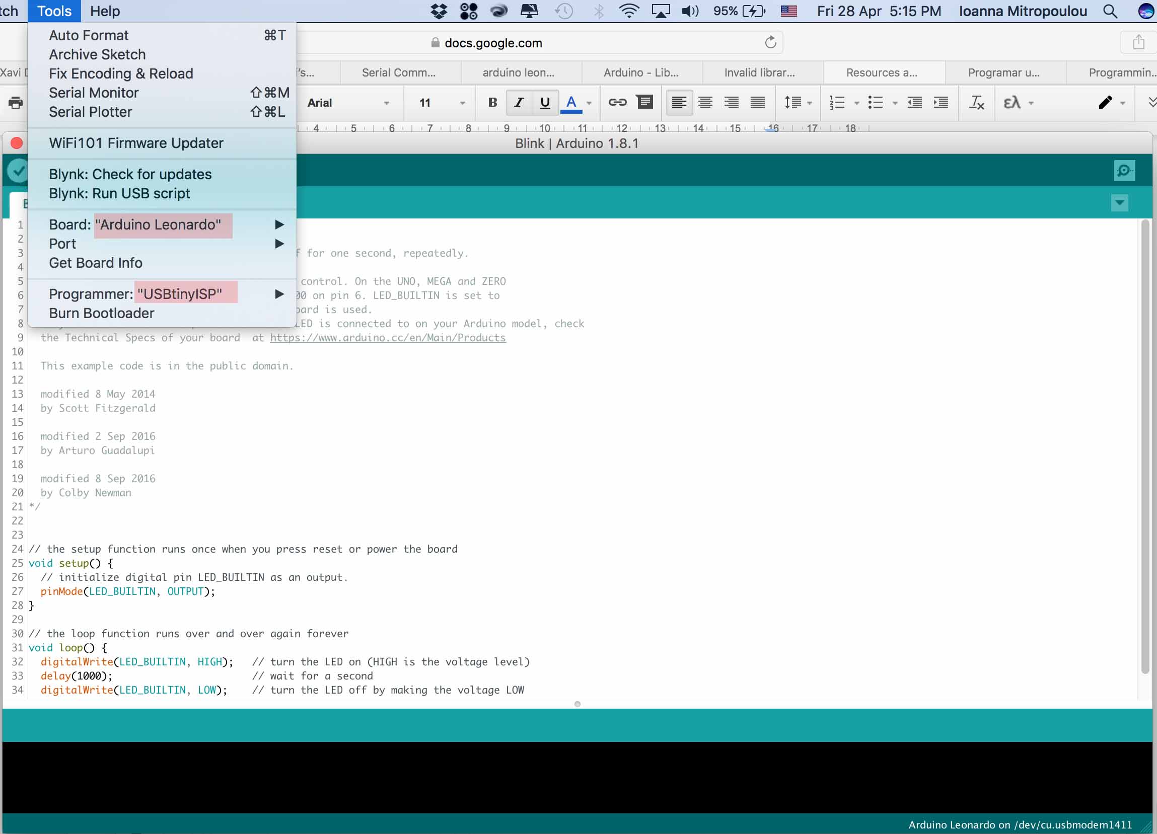
In order to have the correct settings for programming this particular board, the following parameters must be selected on the arduino IDE: Board = Arduino Leonardo, and Programmer = USB tiny.
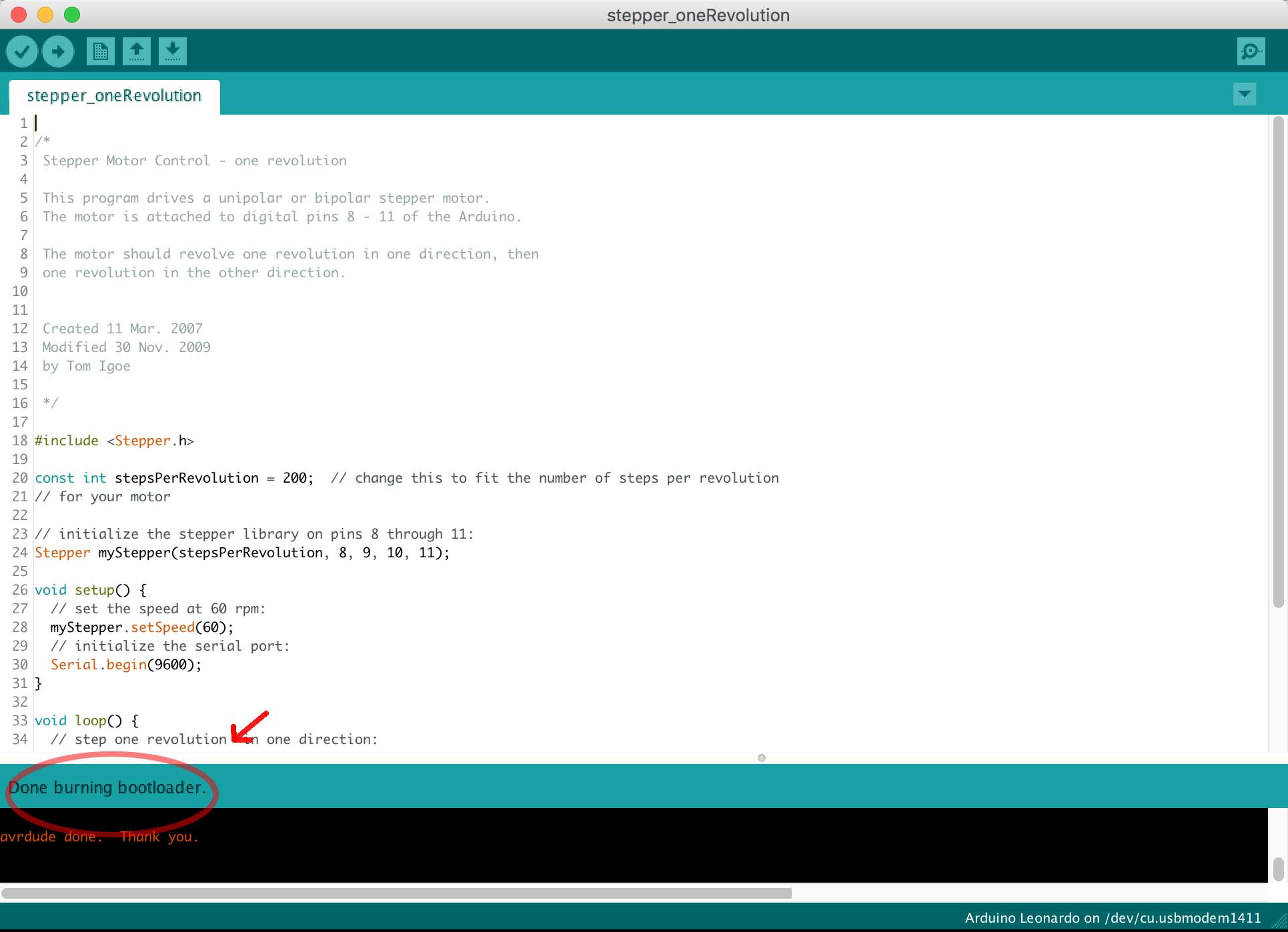
Just like with every new board, in order to prgeam it the first step is to burn the bootloader. To do that I connected the ioanduino with power, and with the fabISP. This process only need to be done once, because then the fuse bits keep their value unless they are explicitly changed.
BLINK
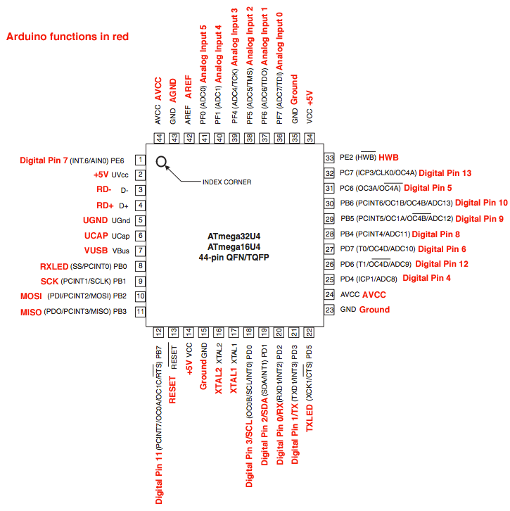
After that is done, the board can be programmed via the mini USB directly from the computer, and the external power is not necessary unless there are big energy requirements from the motors. The first thing I tried was to make a LED blink, in order to check that the board works as expected. In order to address the pins of the atMega using the arduino language, we need to look again on the pin mapping. Now we are interested in the arduino functions (red letters). In my case, I connected the led on the digital I/O 30, which is Digital Pin 10.
So my code looks like that.
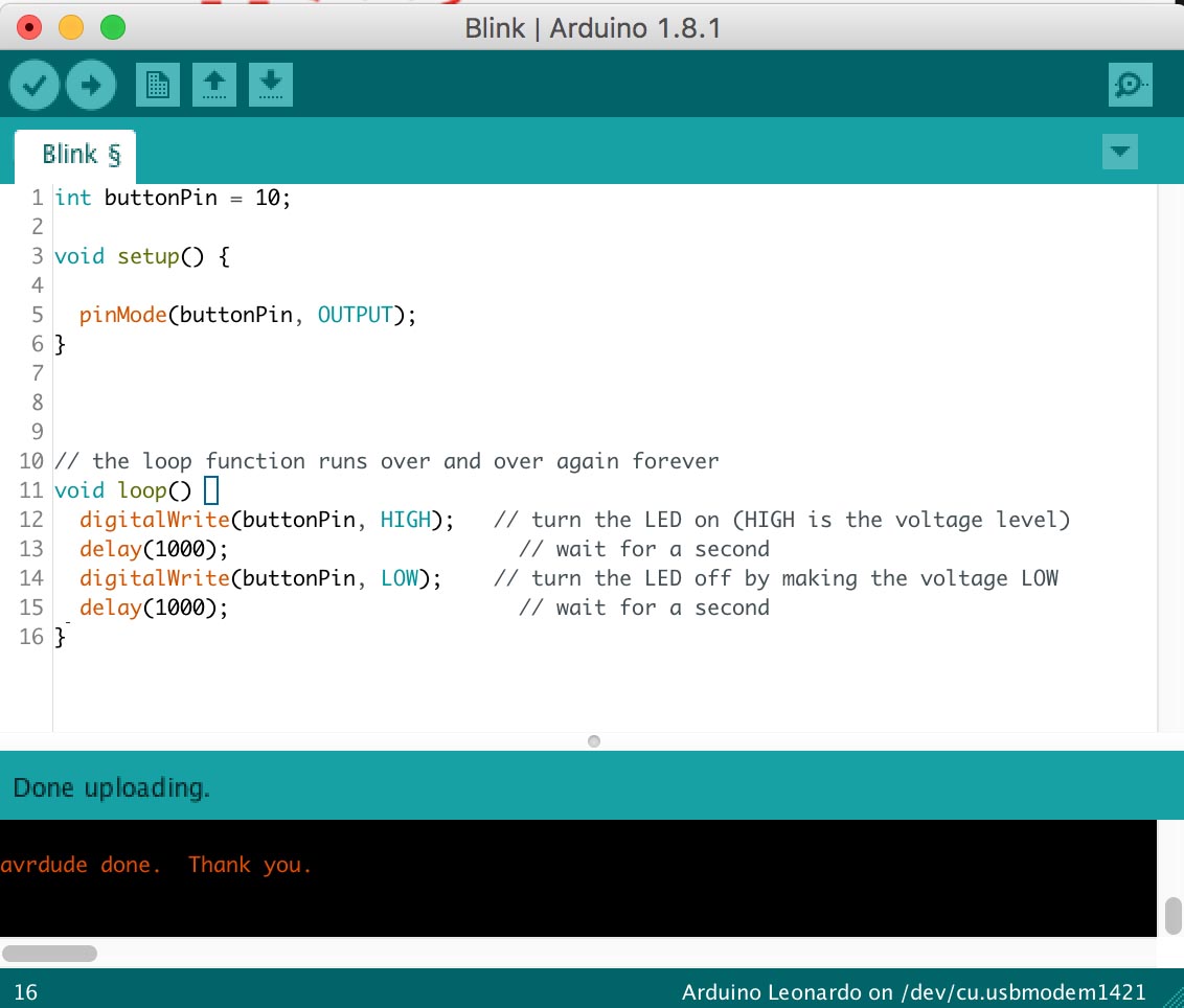
I was really relieved when it worked.
Internal LED blinking
External LED blinking
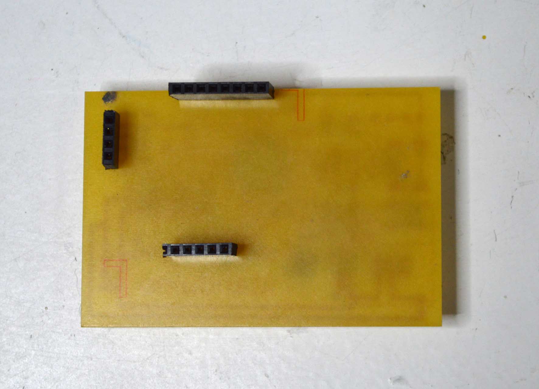
Tip: when working with a breadboard and ioanduino or any other similar PCB, you can get voltage and ground from the ISP programming header. The only problem I noticed is that while these are connected, I couldn’t upload a new code on my board.
SERVOS
The next step was to connect and check the servos. This time I needed to have external power source of 9V.
I connected two servos in the pins 25 and 26, so in the digital pins 12 and 4 (always look at the pinout image above). My code looks like that:
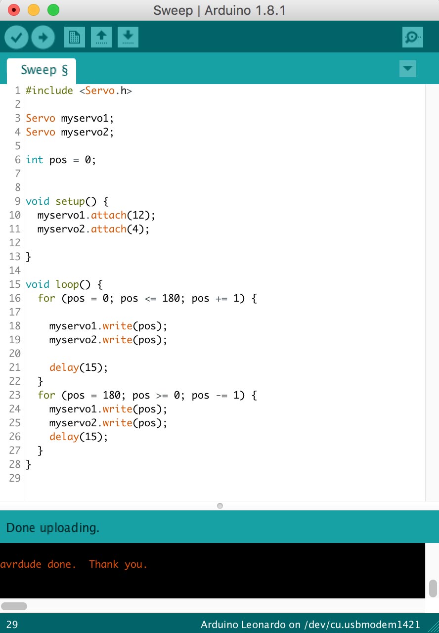
And it works!
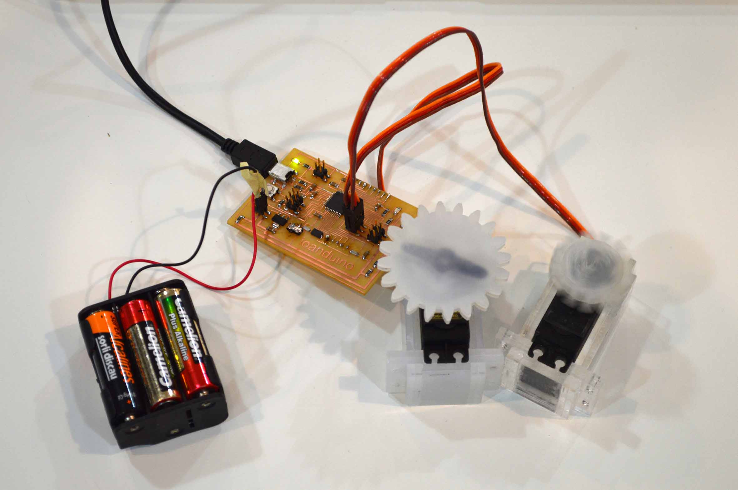
However I noticed after some time using the external power source that powers the motors, the resistors used as voltage dividers became hot. After some research I did, it turned out that I had the wrong idea about voltage dividers, so I decided to remove that part by taking out those resistors, and have the power directly connected to the motors. In any case the divider was supposed to give 8.4V out of 9V, but I noticed using the multimeter that my six AA batteries which were not new gave me a voltage of 8.2V
The next step was to connect the board with an input device . You can find more details about that in the 13th Week (input devices).
After that, I connected the bluetooth module HC-05 with my board using an application I made. You can find more details about these in the pages Week 15 (Networking and Communications), and Week 16 (Interface and Application programming)
A few weeks later
I designed a second version of ioanduino, which I used to power my final project. It has a few improvements making it smaller and easier to use.
Here you can download the files
traces.png
partlist.pdf
schematic (eagle file)
board (eagle file).
