16th Week, Interface and application programming
The focus of this week was on creating an application that interfaces with an input/output device that we made. I found this subject extremely interesting, so I put a lot of time in this assignment.
MIT App Inventor
To develop my application I use the MIT application inventor, which is a very well designed platform for visual programming application for android devices. In a way, it is like grasshopper, but instead of geometry, you make applications. It was the first time I ever used this tool, and I am really happy with it, as it is very powerful and user-friendly, and you can find a lot of tutorials, projects and documentation online.
Once again this week I worked for my final project.
Where was I? Oh yes. I was at the point when I had just managed to connect my ioanduino (see week 10) via a bluetooth module (see week 15) to my phone. Now I need to create the application on the phone which will allow me to control my two servos.
I started by watching many tutorials on MIT app inventor, and I am writing here the ones I found most useful.
Videos:
App Inventor 2 Tutorial-Arduino Bluetooth Control (ΥouTube, 9 min)
How to MIT APP INVENTOR 2 Make a Bluetooth Connection Screen (YouTube, 20 min)
How To Receive Multiple Sensor Readings, arduino - MIT app Inventor 2 (YouTube, 15 min)
App Inventor 2 - Android receive data from arduino (YouTube, 4 min) !!! Potentiometer example
How To Build Android App for your Arduino, MIT App Inventor (Youtube, 9 min) !!! Led example + motor example
Text:
Great bluetooth tutorials for MIT App Inventor, with everything you need to know about bluetooth communication
Part1 (on sending text)
Part2 (on sending numeric data)
Connecting Arduino and Bleutooth
Other useful links:
MIT App Inventor Built in Blocks documentation
MIT App Inventor User Interface Components documentation
Creating my application
Thanks to all the online documentation, I had more than enough information to start on my project.
An interesting thing about the process of creating an application that interacts with an arduino is that you have to be writing two codes at the same time: the application and the arduino code. Those two have to match and cooperate well to get the project working.
The communication between the application and the arduino in my code, inspired by some tutorials I referenced above, is based on a simple logic. This application defines a very simple protocol for communicating with the Arduino. This protocol is merely a 2-byte sequence.
The application always sends the first byte (=number) , which contains a value that we interpret as a “command”. This number points out what this particular communication is for.
(for example, 1 = “I want to receive the position of servo 2”, or 2 = “I want to send a new position for servo 1” etc).
Thanks to this first byte, now both devices know if they should send a byte or receive a byte, and what this byte is for. Then the second number-byte contains the actual value.
(for example 64 = "move servo 2 to 64 degrees").
With this logic, I started building my application. It wasn’t easy, but after a few days of failing I finally managed to put together an Application and an Arduino code that work well. I will explain each side separately, and then put all the codes together.
Let’s start with the App Inventor.
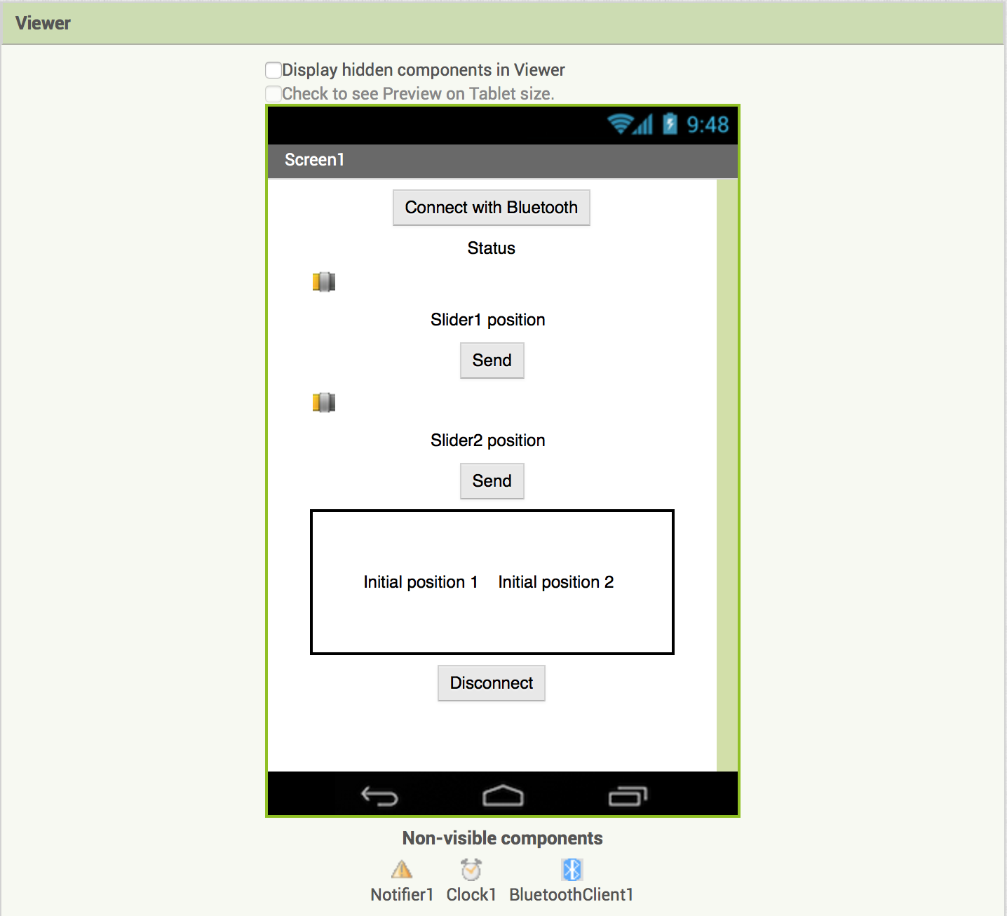
Here’s the designer tab. I created a very simple layout with a list-picker, a few buttons and labels, and two sliders. I also added one Notifier, a Clock and a BluetoothClient (non-visible components). I will improve the design later-on, but for now I wanted to make sure it works.
On the Blocks tab is where you put all the functions to make it work.
ESTABLISHING CONNECTION
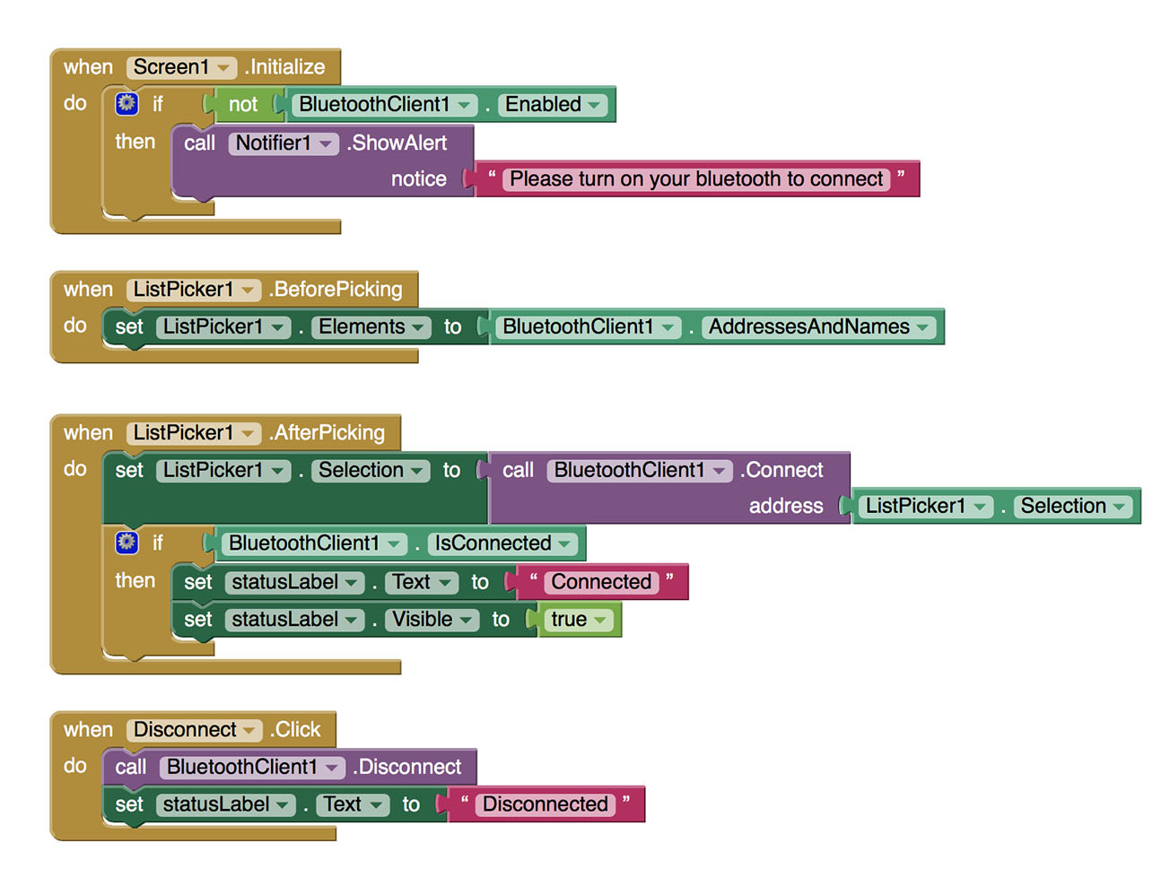
This first part concerns the list-picker on the top of the screen which establishes connection with the bluetooth once clicked.
CLOCK-UPDATE STATUS
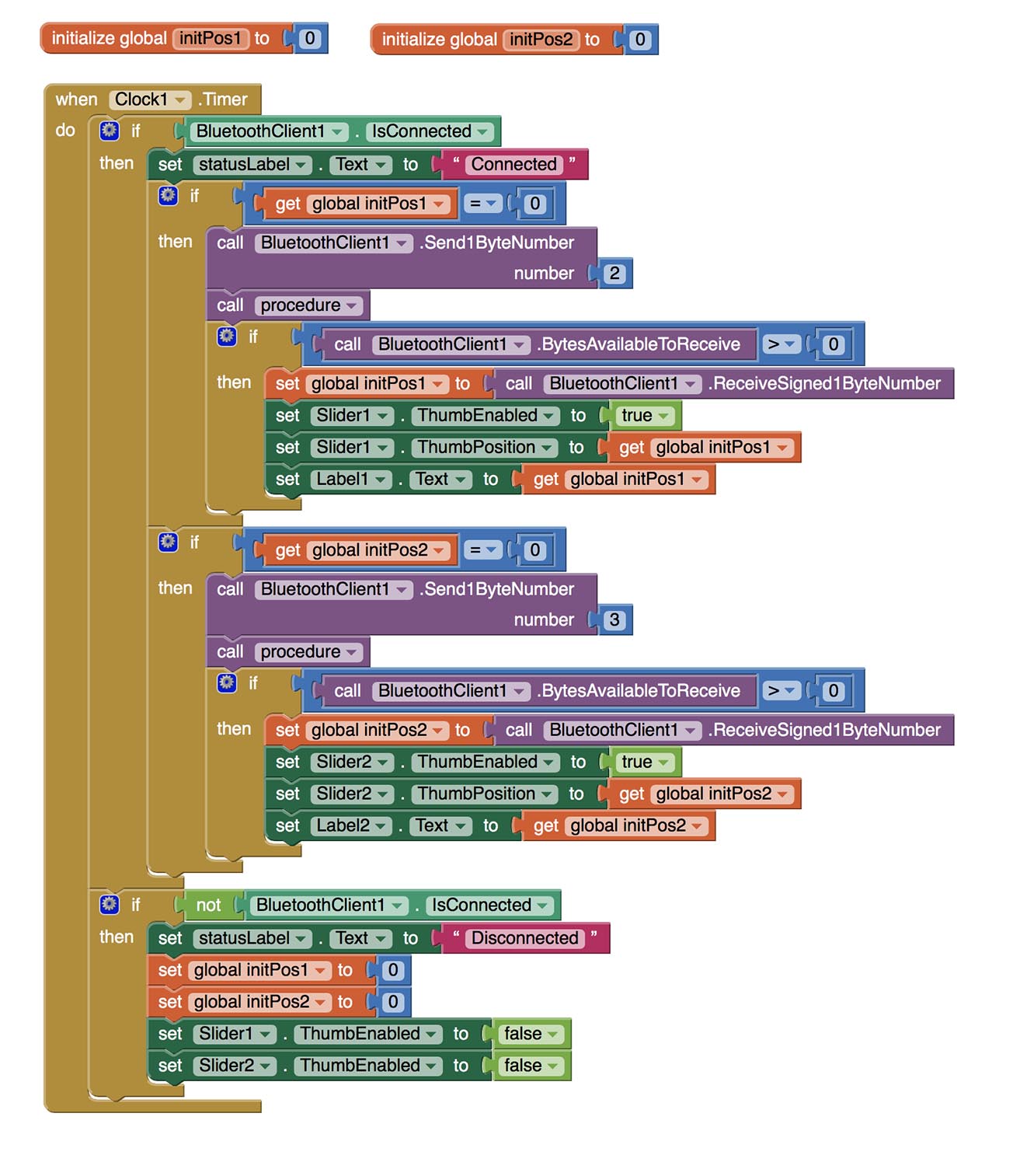
What happens here, is that every time the clock ticks (once every second), it checks whether the application is connected with the bluetooth, and updates the “Status” label to say: connected/disconnected, and then also updates the other components (sliders and buttons) accordingly. This is the basic function of this part, but not the only one.
When the phone establishes connection with the bluetooth, it has two global variables (initPos1=0 , initPos2=0 ), which it needs to fill with numbers of the current position of the servos. So if the values of those variables are 0, then it starts communicating with the arduino in order to acquire the current position of the two motors. The communication goes like that:
from Application (Command)
-2from Arduino (Value)
-number (position of first motor) —> stored in initPos1from Application (Command)
-3from Arduino (Value)
-number (position of second motor) —> stored in initPos2
After that, each time the clock ticks, if the variables are not 0, it doesn’t ask anymore for those values, because it needs them only to initialise, so that the sliders that will control the servos are in the correct position.
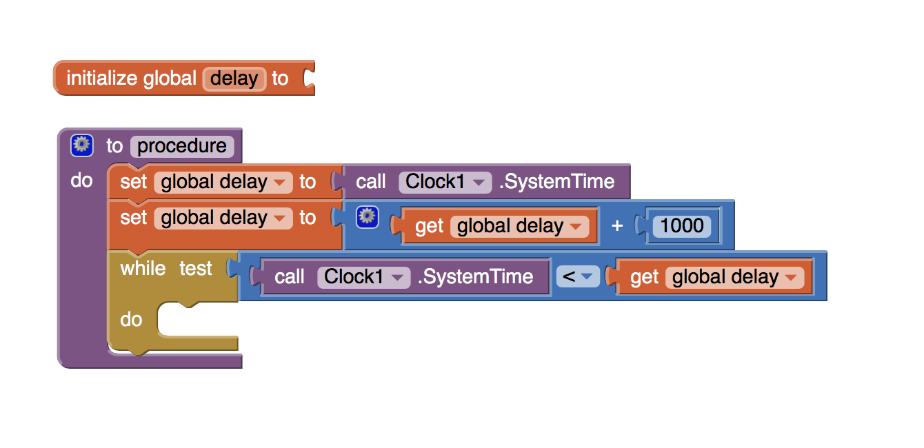
DELAY
A problem I had in the clock part is that when the Application sent the first command, it wouldn’t receive any byte from the arduino. With the next command it would receive the previous byte, and so on, always receiving the answer of the PREVIOUS command. I’m not sure why this was happening, but I guess it might be because of some delay on the answer by the arduino. To solve this I created an extra delay function which I put in the Application blocks always after sending the command and before starting to expect its answer, so that the arduino has enough time to send back the data. What this function does, is basically telling the Application to do nothing for some milliseconds. So this is what that mesterious "call procedure" was the clock's blocks inbetween sending and receiving bytes. I don’t know if that’s the best way to do it, but it worked. Here’s how the delay function is made:
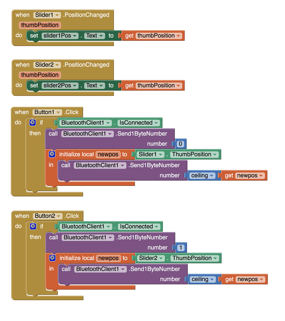
SLIDERS CONTROLLING THE MOTORS
Finally, in this part the the value of the sliders is sent to the arduino when the button “Send” is pressed. Again with the 2-bytes communication protocol I explained before, here the application always sends data, and the arduino always receives. The communication this time is like that:
from Application (Command)
-0from Application (Value)
-number (desired position of first motor) —> move motor 1from Application (Command)
-1from Application (Value)
-number (desired position of second motor) —> move motor 2
This time I didn't need a delay to wait for a response, so here are the blocks:
Now let’s take a look at the Arduino code.
When a desired new position is set for a motor, it moves in steps of 1 degree each time, with a delay in between, because I need it to move slowly. To make the code cleaner, I put this in a separate function (void servoGo(Servo servo, int destination, int initialPosition)). Apart from controlling the two motors, I also added a LED on the arduino code which blinks with different speeds according to the Command it receives. The purpose of this is for debugging, as it is really helpful to have a blinking LED when you have no idea what is going on or why something doesn't work. This is on the separate function (void flash(int wait)).
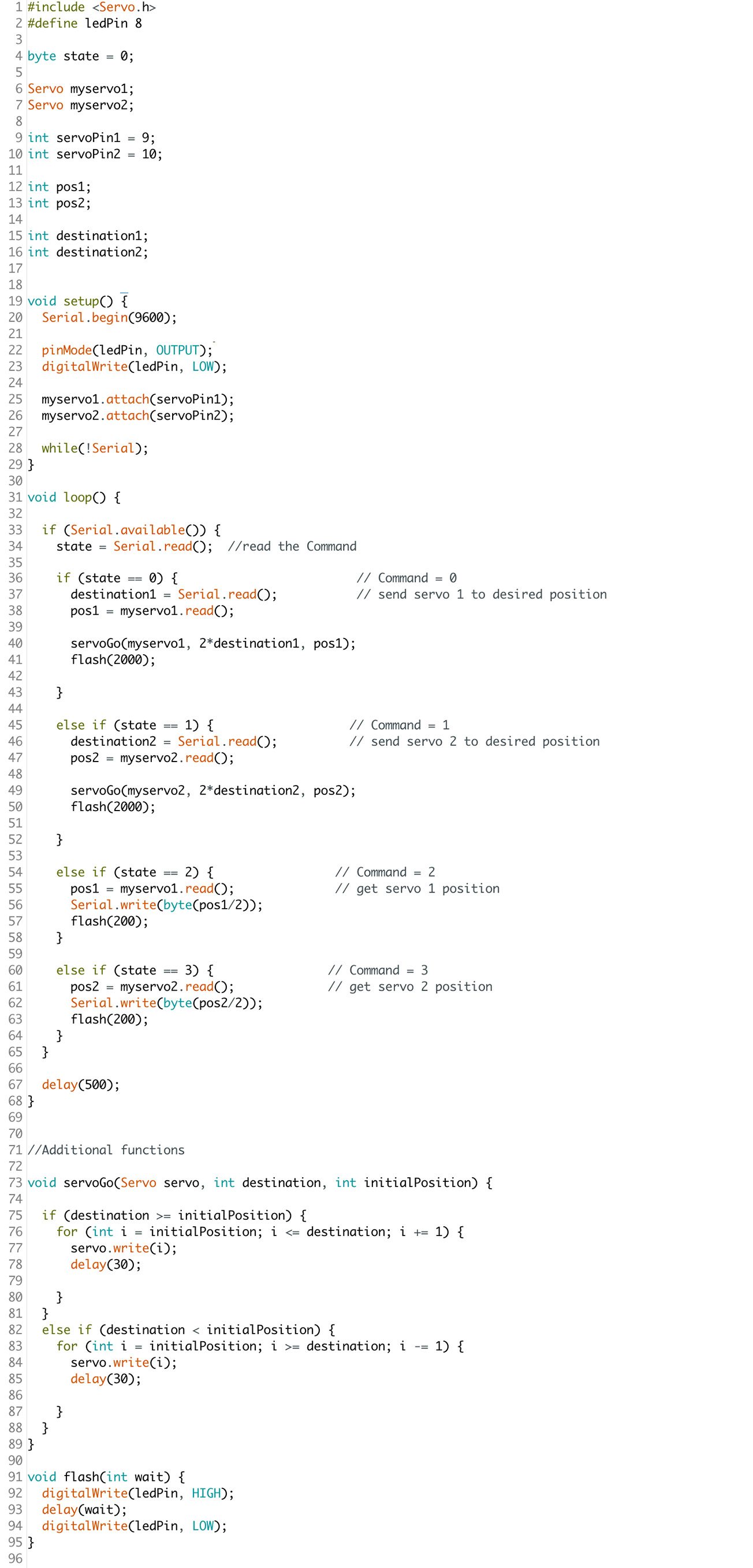
In the following image, I have put App Inventor blocks and arduino code side by side, in order to illustrate the two-bytes communication I mention above.

Each data sent must be packed in one byte. The values that need to be sent are numbers from 0 to 180 (the rotation span of my motor). The numbers that can fit in one byte are values from 0 to 255 or from -128 to +127 (as the “-“ counts as an extra bit). Apparently both the App Inventor and the Arduino work by default with the 128 to + 127, because I noticed I couldn’t send values above 127, and I didn’t know how to change that. So, to simplify my life, the Application uses values from 0 to 90, and then this numbers are multiplied by 2 on the arduino sketch before they are sent to the servos. This reduces slightly the accuracy of the movement, but I think this is imperceptible in my project.

In summary the application works as such. When the bluetooth connection is established, the Application sends the commands that ask for the current position of the servos, and initialises the sliders. For each value it gets the LED blinks fast once, and that is wy we see the LED blinking twice while the phone is connecting to the bluetooth. After that each time a slider is changed and the button "Send" is pressed, the Application sends a new desired position for the servo, and when the movement is finished, the LED blinks slowly once.
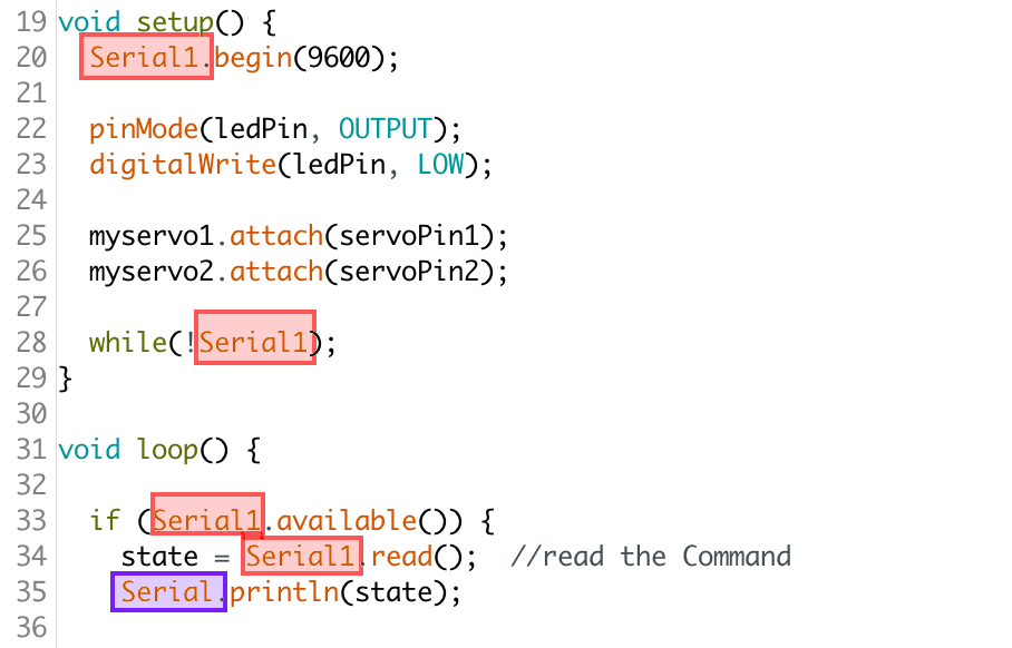
After I tested it with an Arduino Uno to make sure it works, (actually it worked with the 50th test, definitely not the first), and I improved some details concerning the Application, I was ready to upload it on my ioanduino. As I mentioned in week 15, arduino Leonardo (which is what ioanduino is based on), has slightly different serial communication protocoles. So instead of Serial we have to use Serial1 when we are refering to the pins RX-TX, but in order to print on the Serial Monitor we need to use Serial.print. So only a few changes are necessary in the code:
Controlling motors. Ioanduino-Bluetooth-android from Ioanna Mitropoulou on Vimeo.
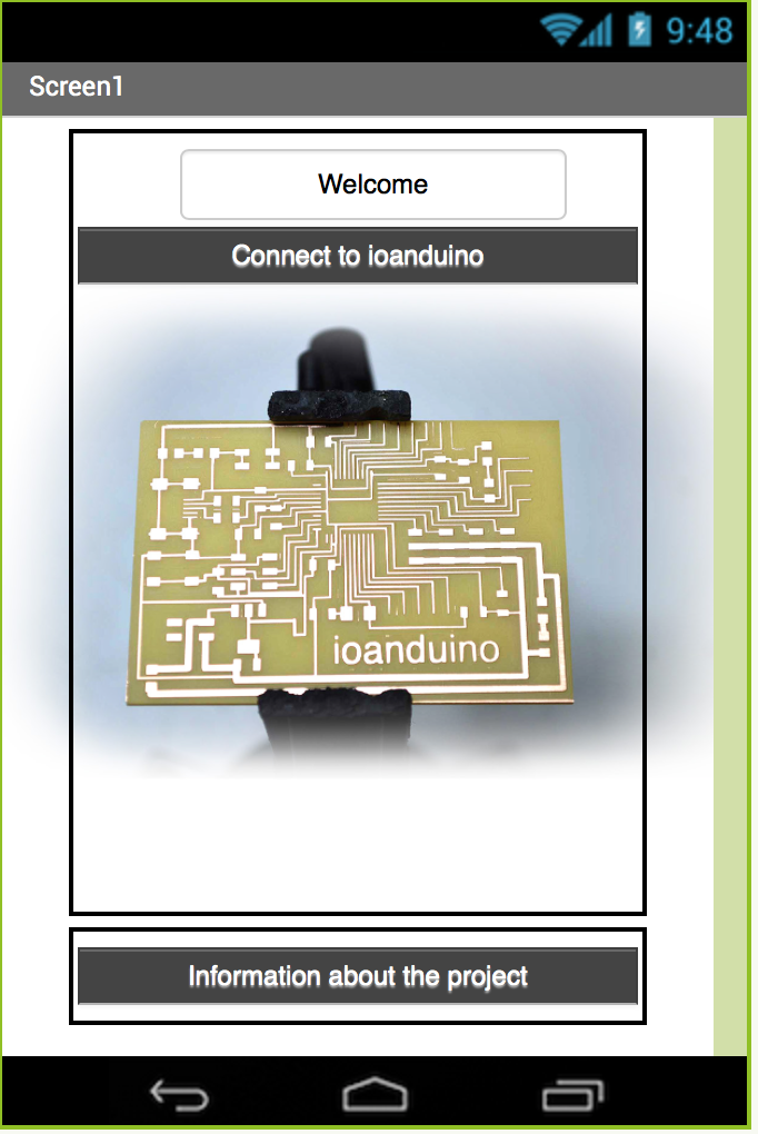
The last step was to design a nice Entrance screen for my Application, with a warm Welcome and information on my project. That was a very easy job with the MIT App Inventor. This is probably not final, but that's how I think it should look like.
And here are the blocks for switching pages.
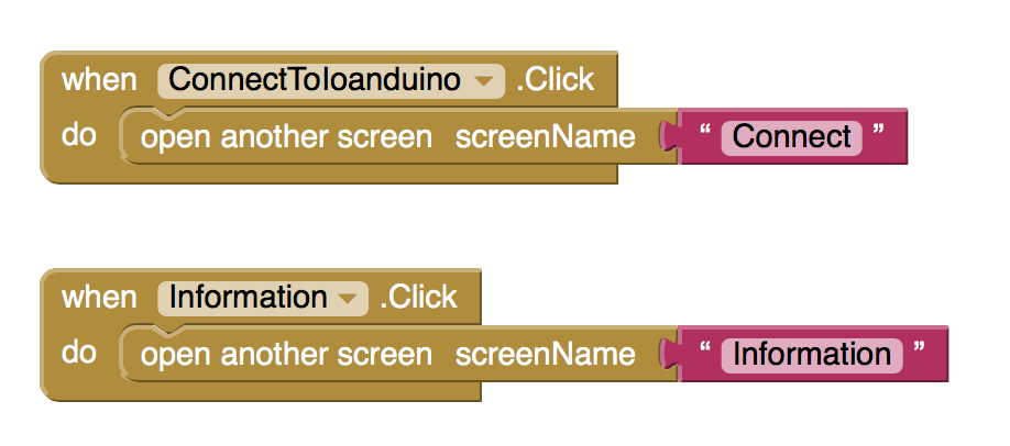
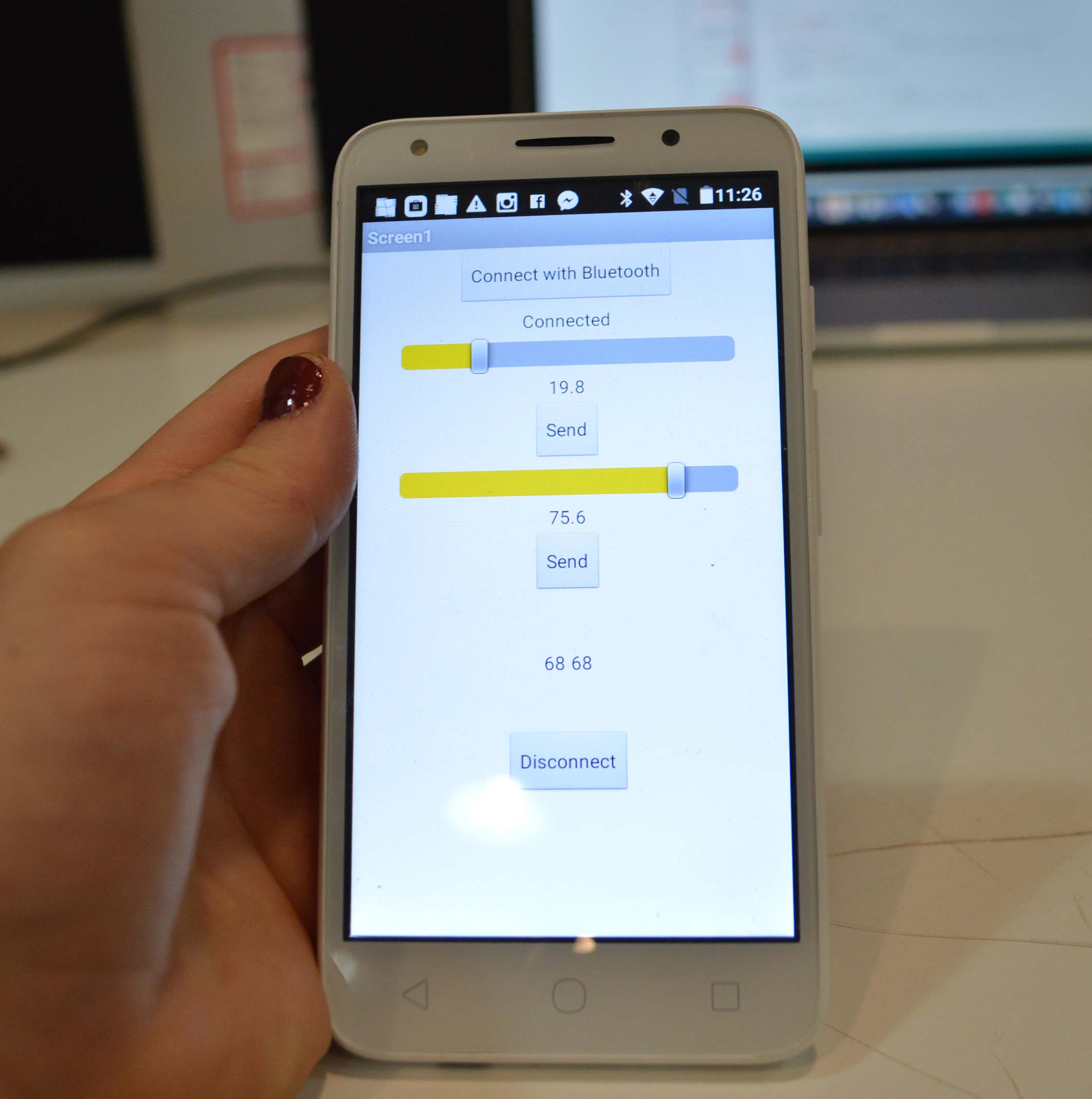
And here's the application in action
Here you can download the arduino code: _ioanduinoBluetooth.ino