3rd Week, Computer-controlled cutting
This week we focused on computer-controlled cutting, primarily with the use of vinyl cutters and laser cutters. The overall assignment of the week was to design parametrically and produce a press-fit modular construction kit, which can be assembled in multiple ways.
Laser cutter
Laser cutting is a technology that uses a laser beam to cut materials, and is typically used for manufacturing applications. It can cut cardboard, wood, acrylic, some types of plastic, and sometimes also metal. The focused laser beam is directed at the material, which then either melts, burns, vaporises , or is blown away, leaving an edge with a slightly burnt surface finish.
We started making tests on the laser as a group. We cut several pieces of cardboard, and then experimented on slots for joints with different values of tolerance. What is interesting is that if the laser cutter is not always perfectly focused, then the kerf changes and this of course affects the tolerance. Unfocused cutting can cause many such problems of bad fitting between the pieces, but it can also be useful in case thicker lines are required.

For example in this test we realised that changing the slots by 0.05 mm is not big enough to make a difference, as a result most slots are almost the same. That is why we then made a different test, changing the slots by 0.1mm and the results were much more interesting with each slot being different. What we realised at the end is that in our laser cutter the width of the curf is such that there is no need for extra tolerance to be added in pieces that are joined together. This means that for example if you want to pressfit two pieces that are 3mm thick, then your slots should be 3mm wide as well. Here you can download the file for the test on the laser.
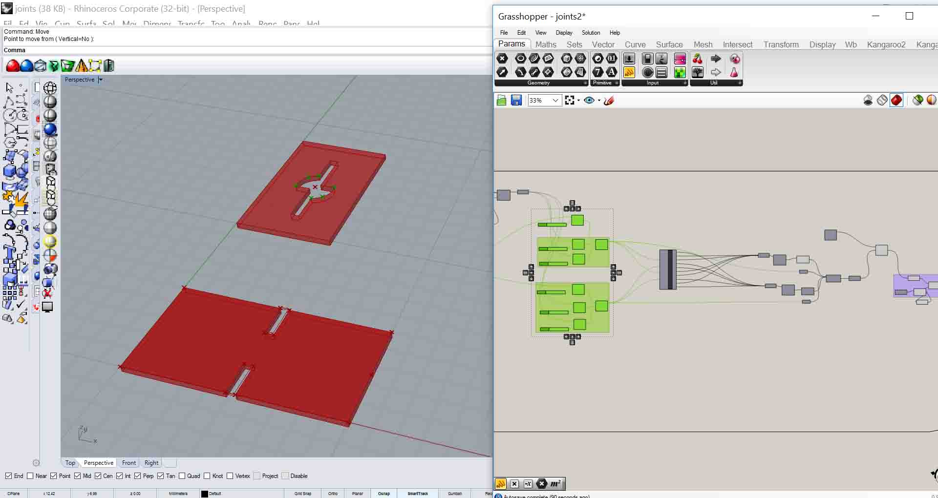
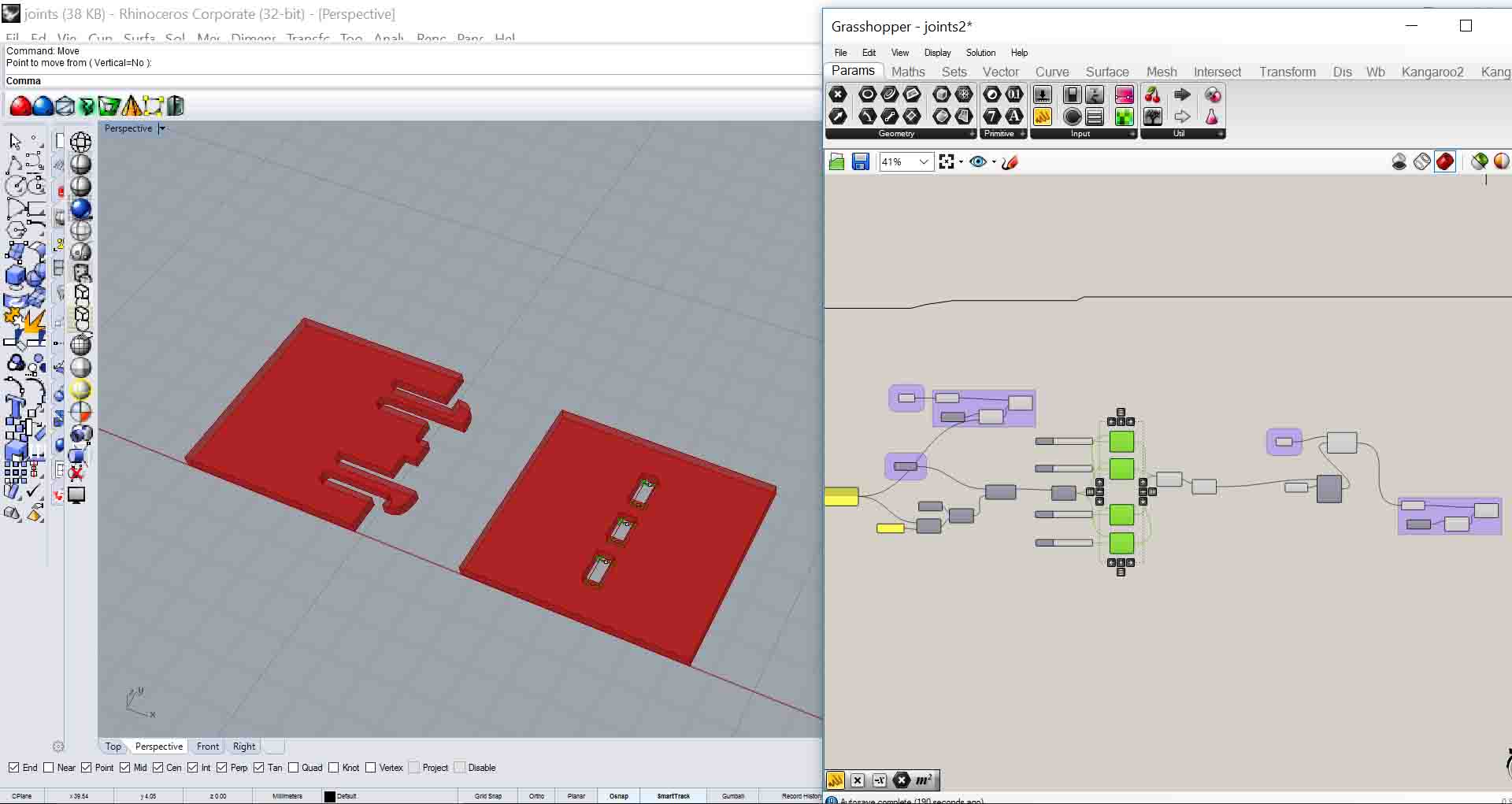
When I started feeling confident with the laser cutter, I set off to design my press-fit construction kit. I started modelling parametrically a variety of joints in grasshopper. In those models, not only the tolerance can be changed parametrically, but also the dimension of the one piece of the joint, so that the other adapts.
I am a big fan of 100% parametric models in Grasshopper that do not need a Rhino file, but what I learnt from this experimentation with joints is that Grasshopper is most certainly not the right program to make joints 100% parametric, because it is very difficult to control points, boundary lines or faces of geometries with a lot of details. So I had to ignore my loyalty in only-parametric-files, and use Rhino to design some joints and then grasshopper only to change the tolerance for the cutting. Which made the task really easier and faster. But don't let anyone know.
Here’s the grasshopper file: joints.gh
And here’s the Rhino file: joints.3dm, (remember, it’s only for this one time!)
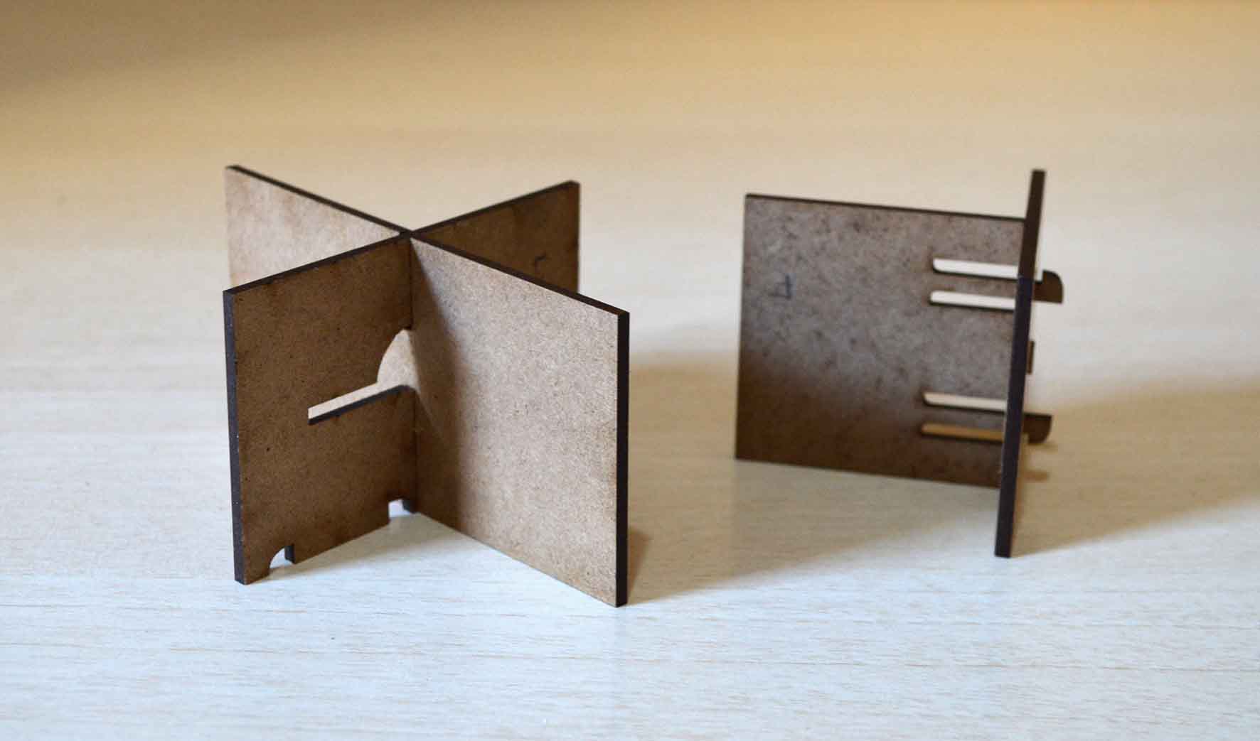
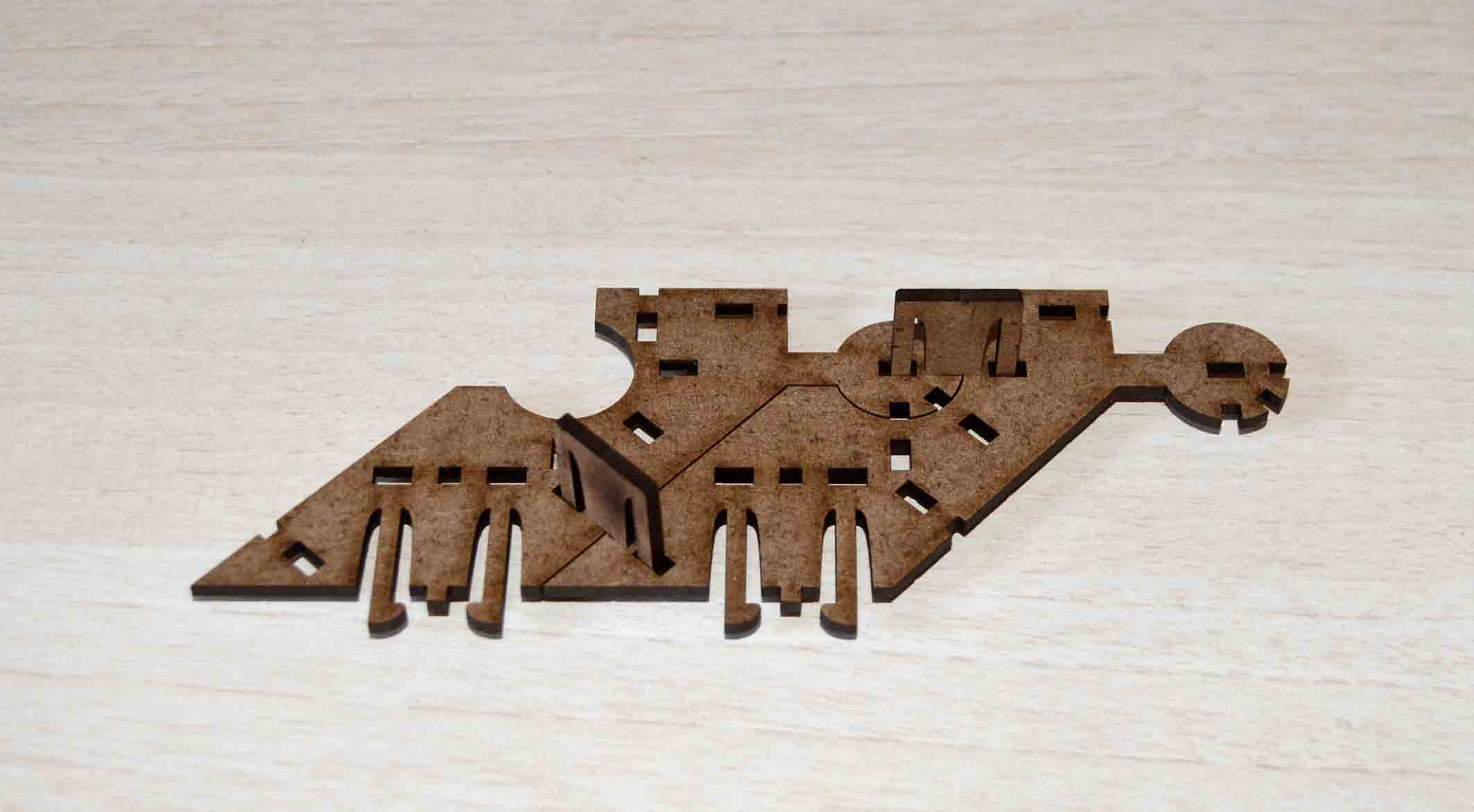
I did the same for the design of my kit. I wanted to have as few and as simple distinct pieces as possible, but at the same time offer as many possibilities for connections as possible in three dimensions, so that complex wholes can be achieved. What I came up with was a combination of different joints in one piece.
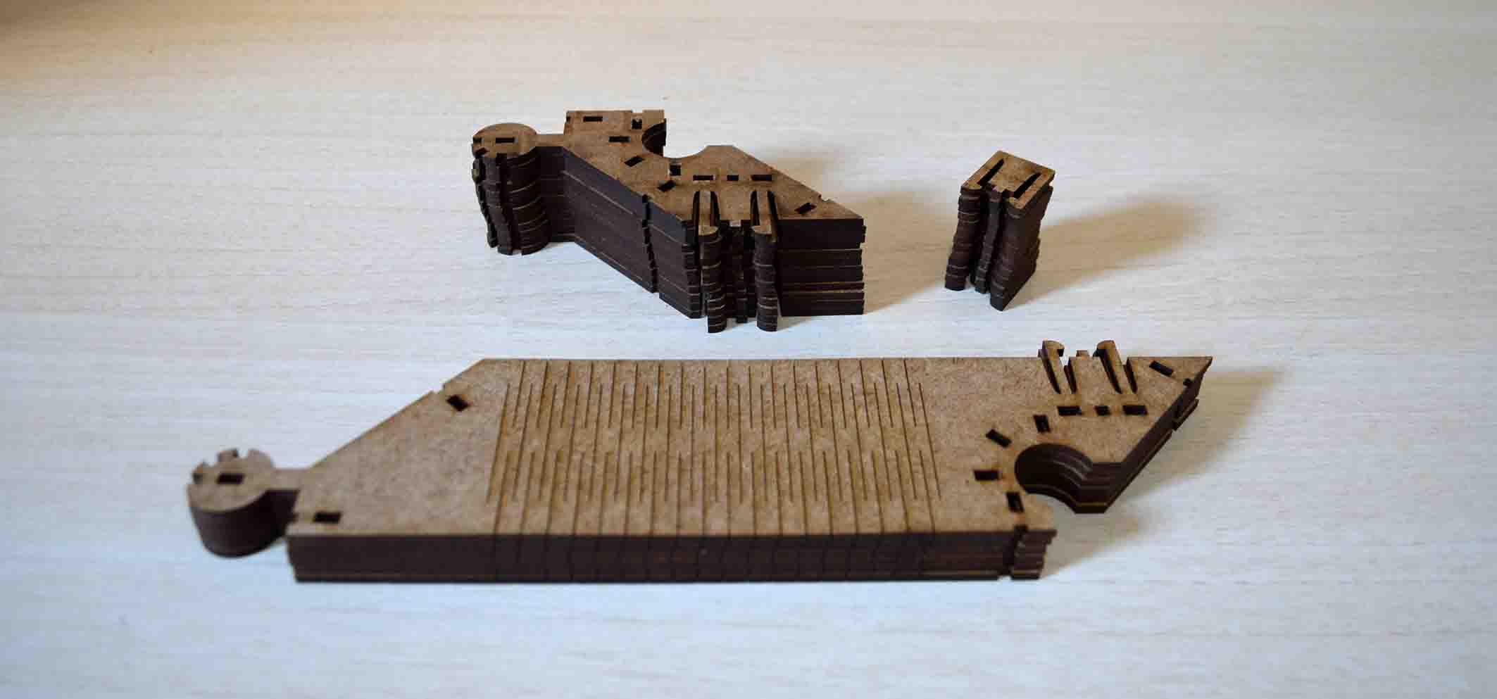
What is more, I wanted the piece to remain as small as possible. This is why I soon had to give up on cardboard, as the one I was using (which admittedly was not the best quality) couldn’t withstand any forces on the thin parts. And to be honest, the parts are indeed very thin. I had to either change my design or my material. What I opted for was to use the scraps of 3mm mdf plywood that always exist in the fablab.
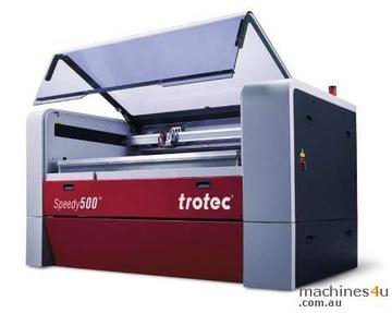
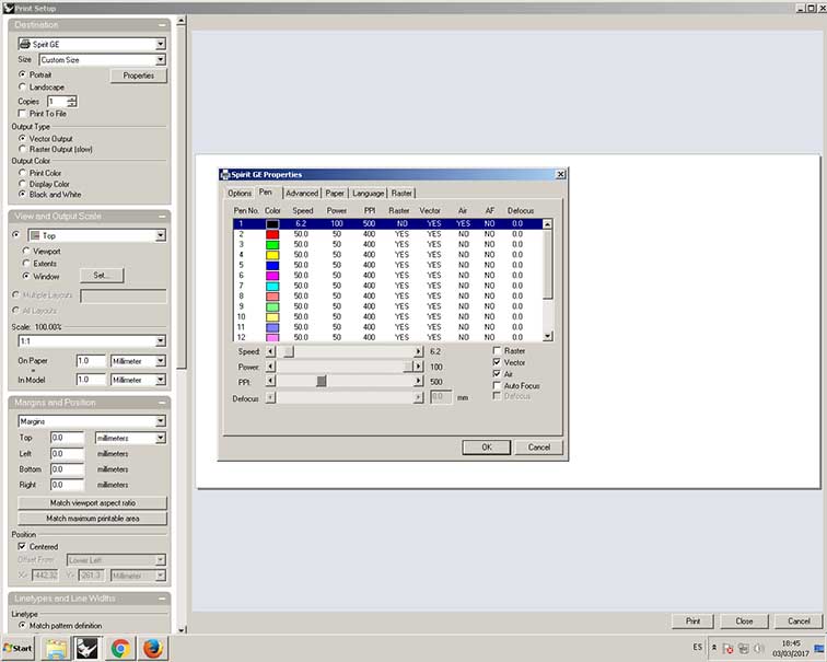
The machine I used to cut is the Speedy 500TM in the Valldaura Green Fab Lab. The settings I settled on after a few tests was: Power 100%, Speed 6.2% and PPI 500. The file run with air supply.
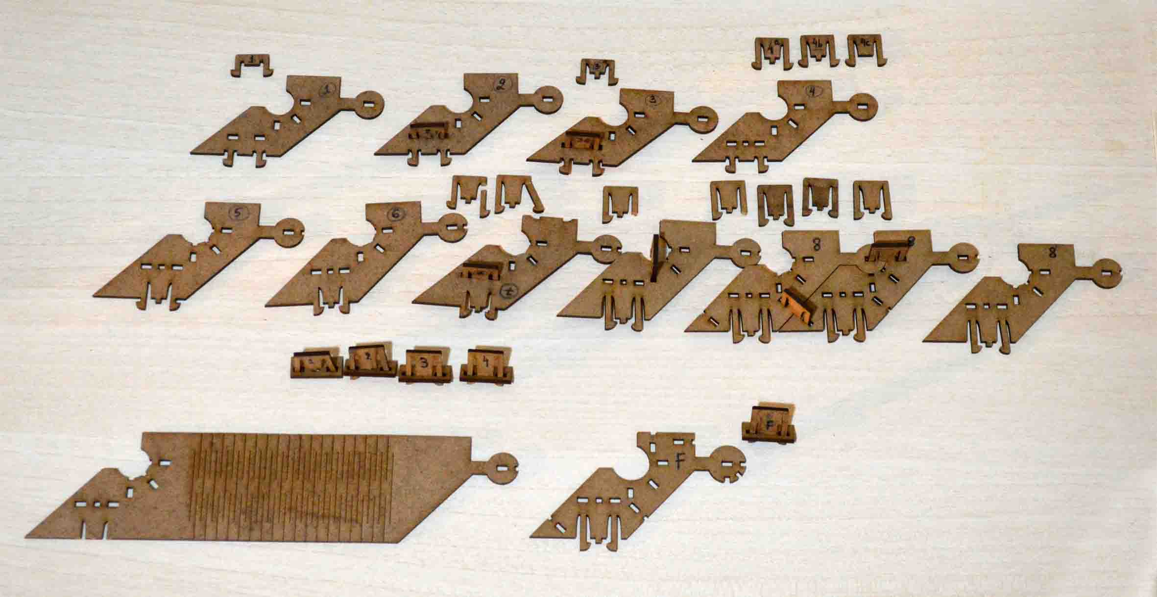
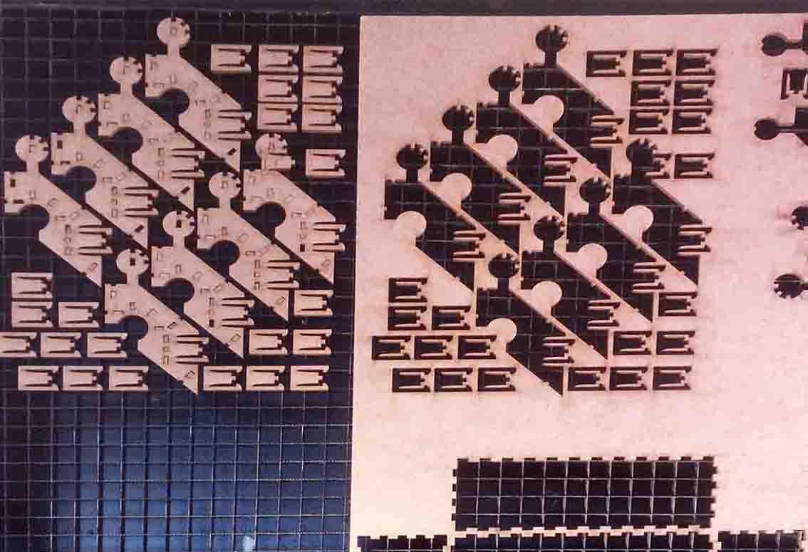
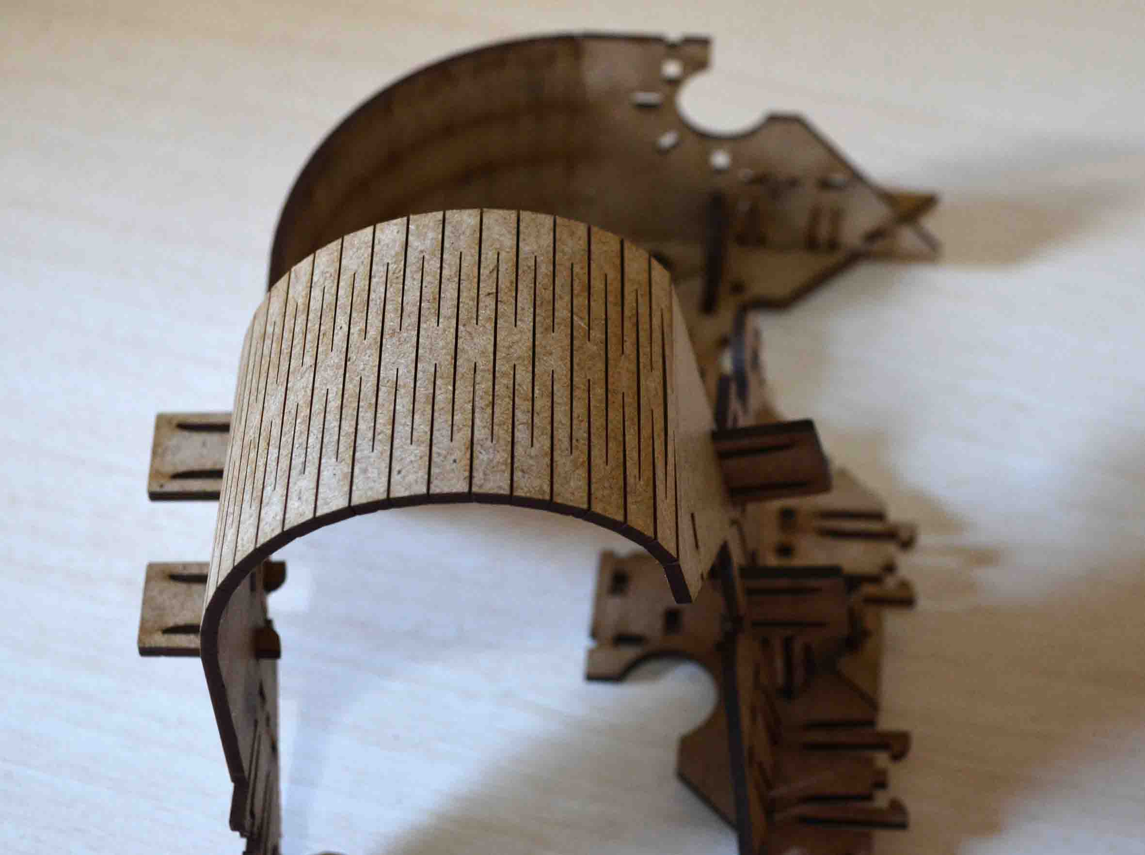
I had spent a lot of time working on my “module”. But when I actually cut it out I realised it was fundamentally wrong. And so a long process of improvements began. I produced about 8 versions before the final one, and during that process I learnt a lot about both the material and the laser. Here’s my series of failures.
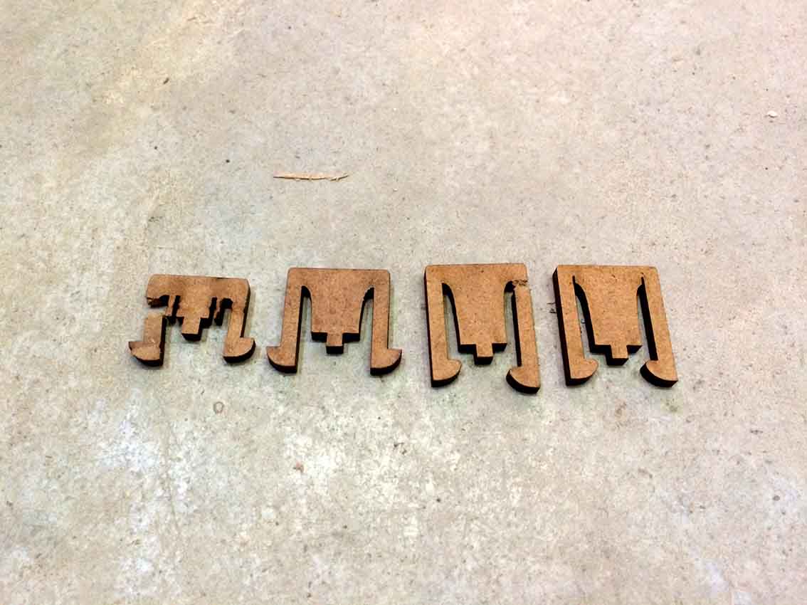
Development process
As you can see from my pieces produced during the development process, what had to change was not the overall design, but rather small details, such as tolerances and dimensions of parts. It took me more than one effort to arrive to the final design because this was an exploratory process of trial and error, during which I tried a lot of things, not all of which worked. This is why I was naming my pieces in generations, so that I cound always compare the current generation with the previous one and see what works better and what doesn't.
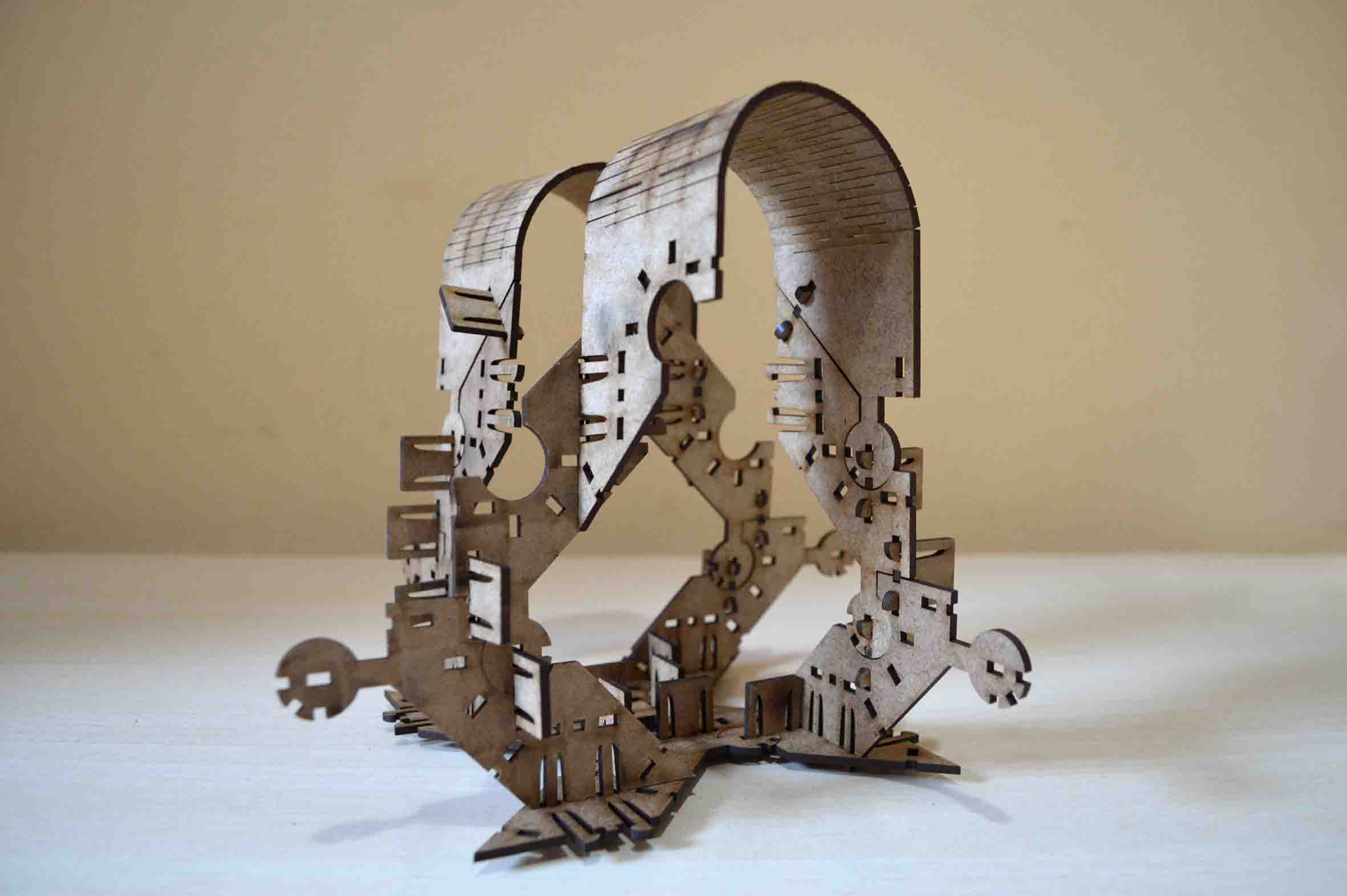
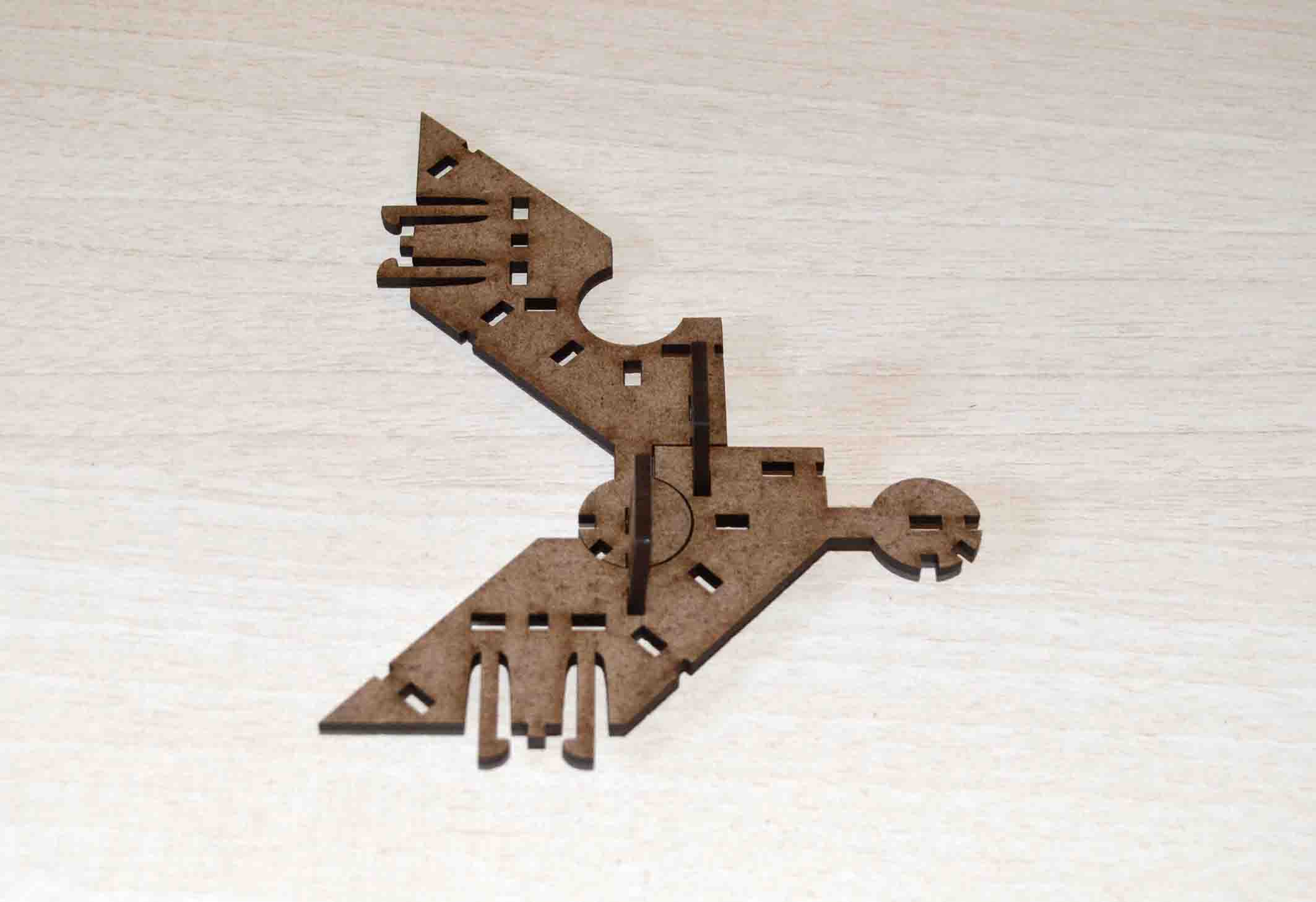
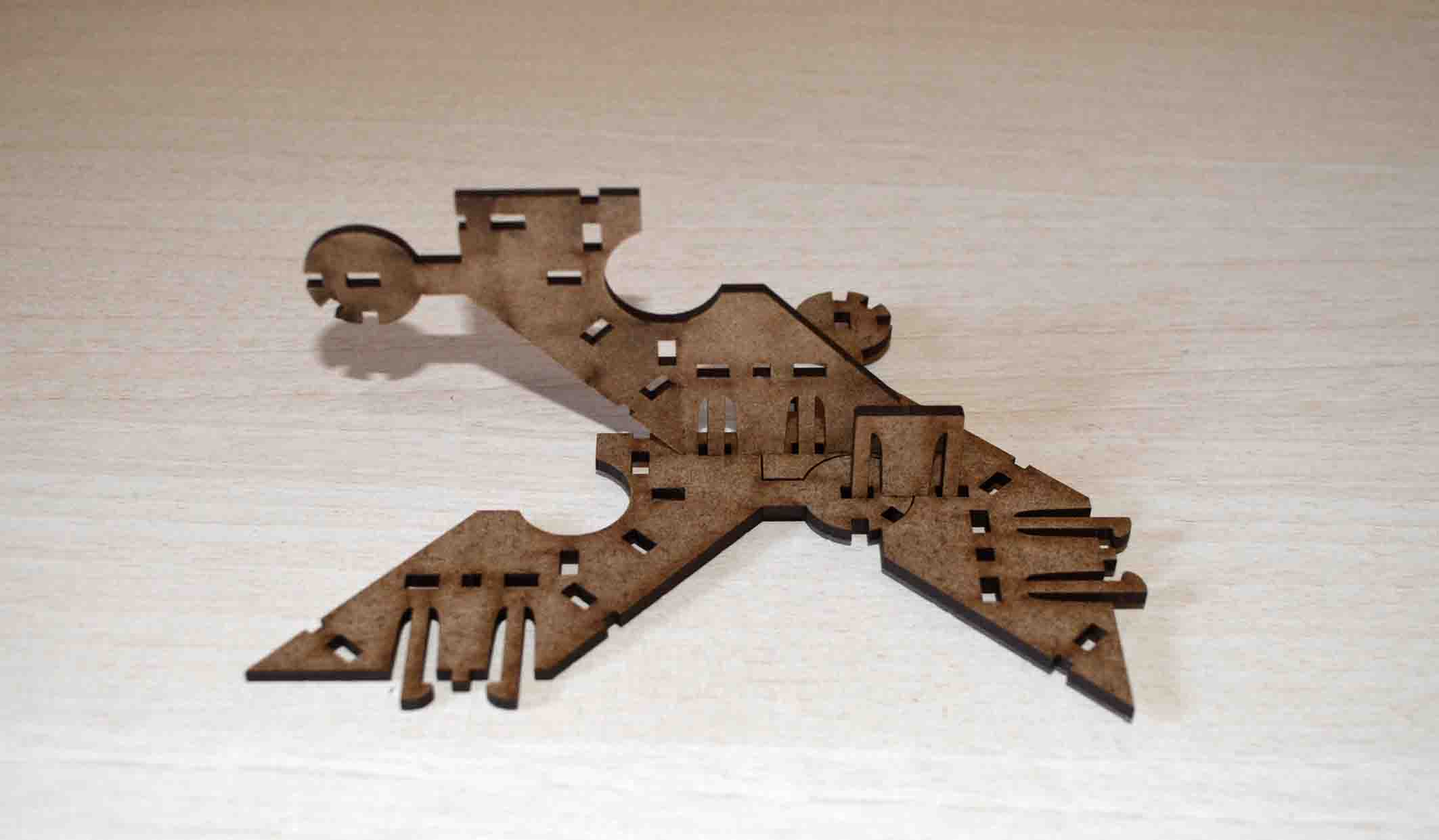
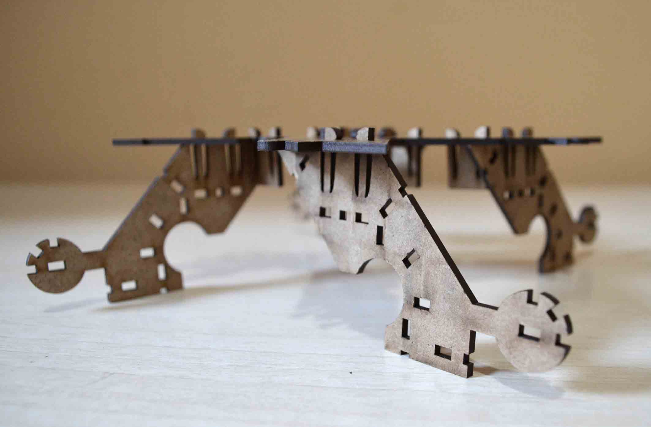
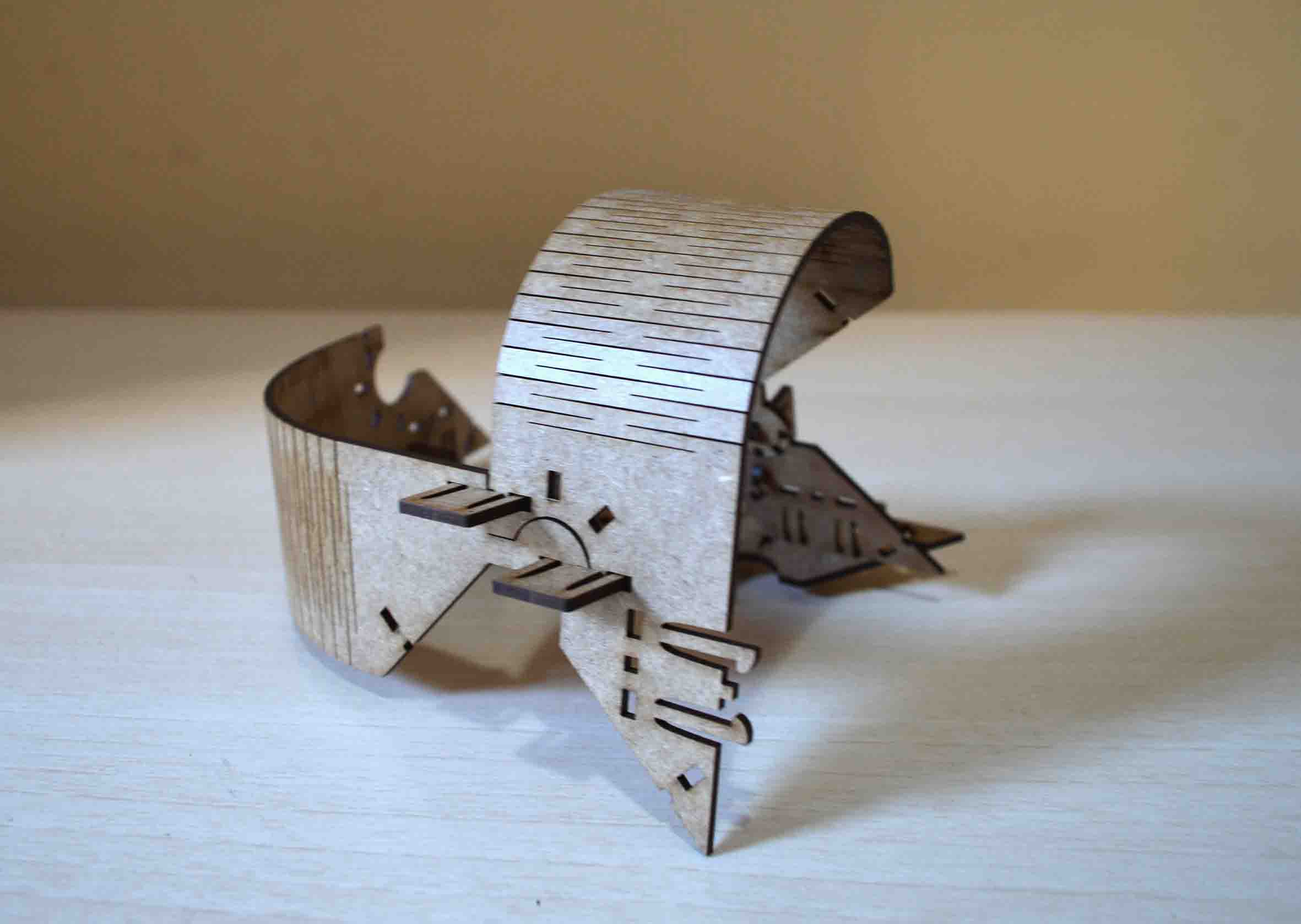
The final module is not at all perfect, but it works. Or at least it fulfils my two basic requirements: when it is joined with other pieces the connection is stable, and it can be assembled and disassembled many times without breaking. I ended up making two versions of the final module: a long one and a short one, plus a connector for stabilising the whole. Here they are.
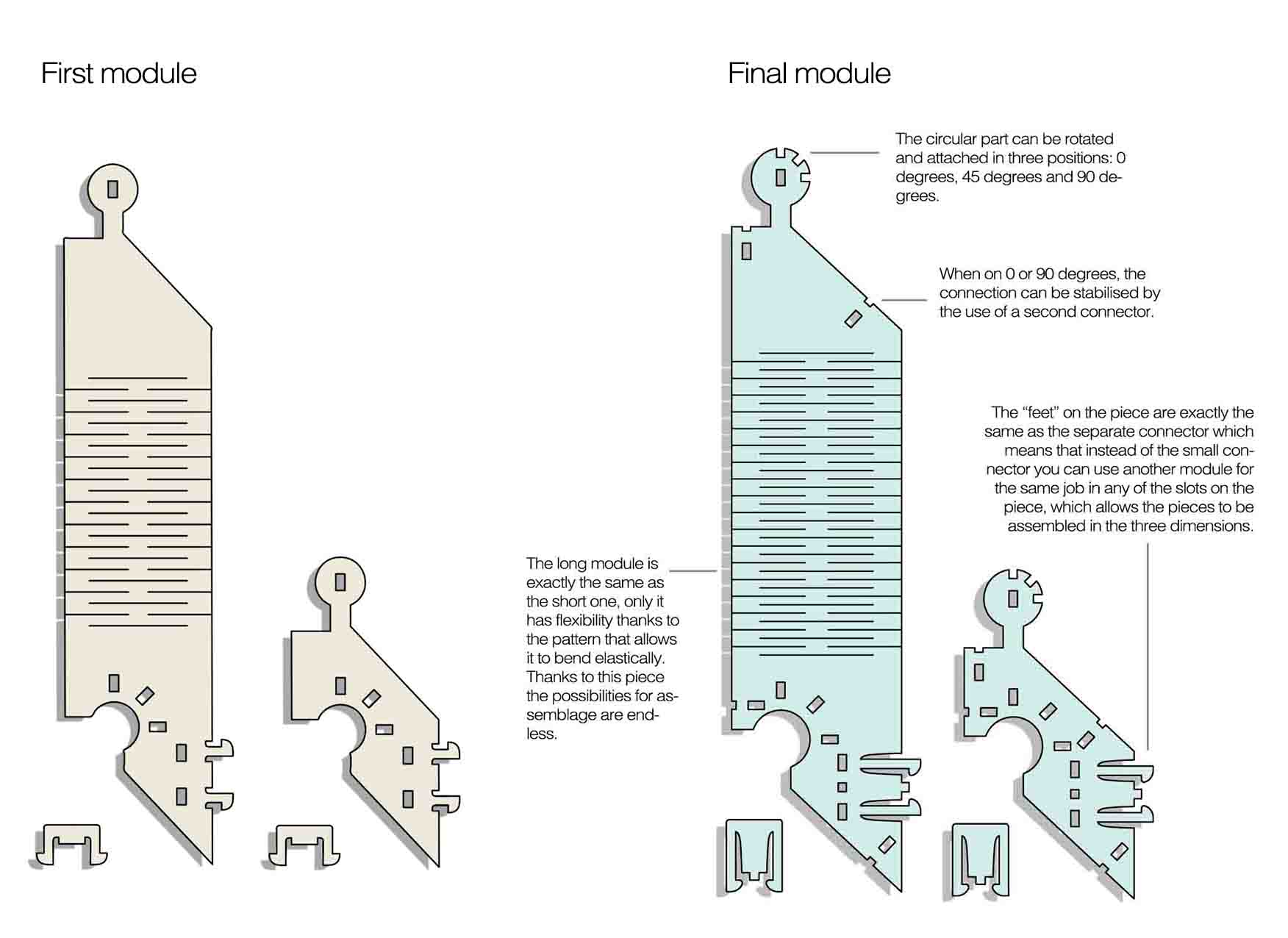
Here’s the Rhino file of the final module: constructionKit.3dm
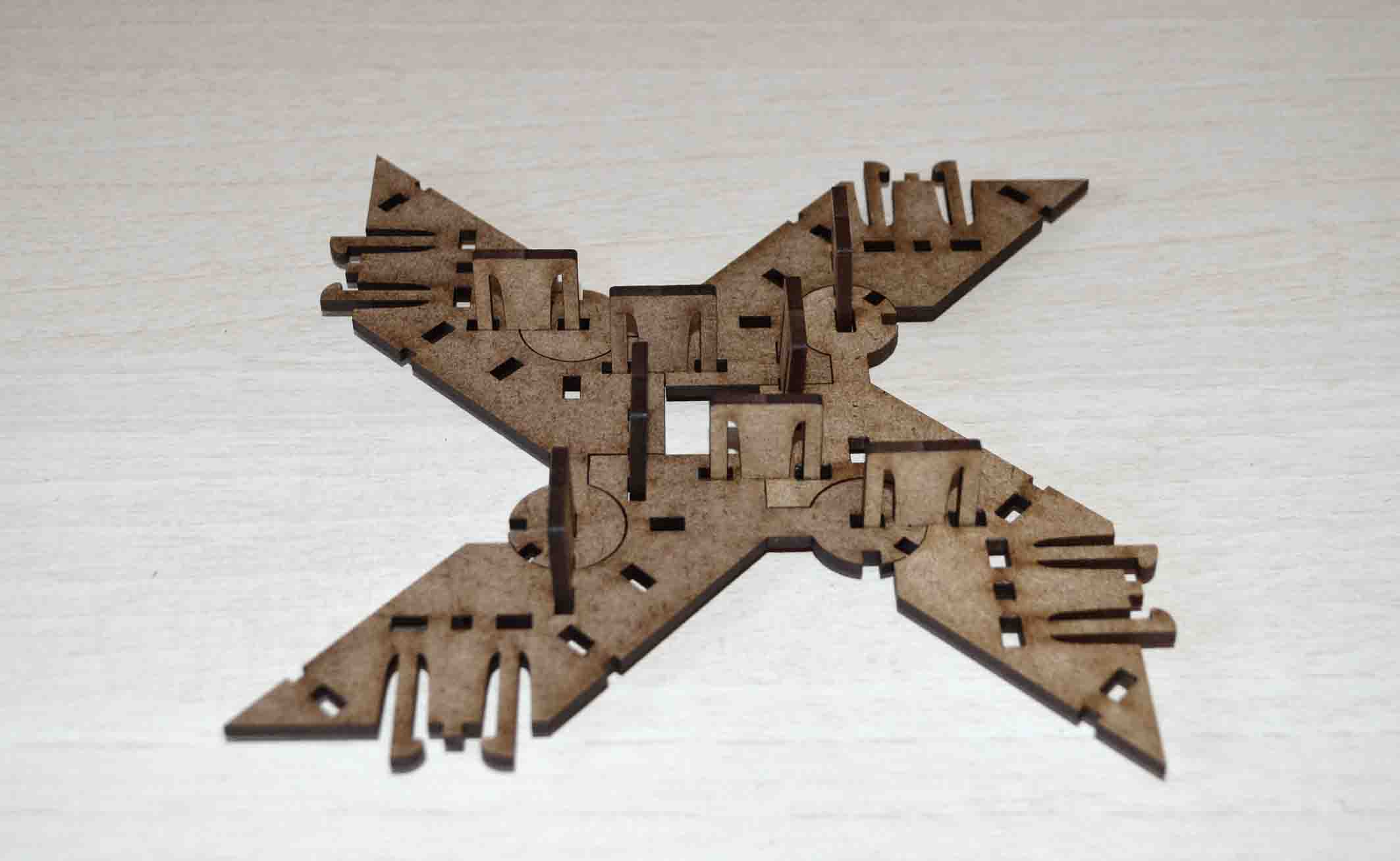
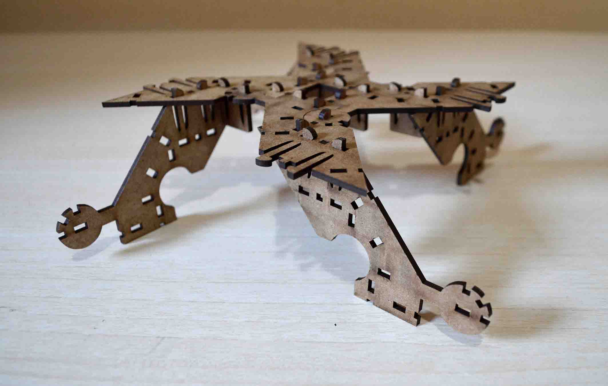
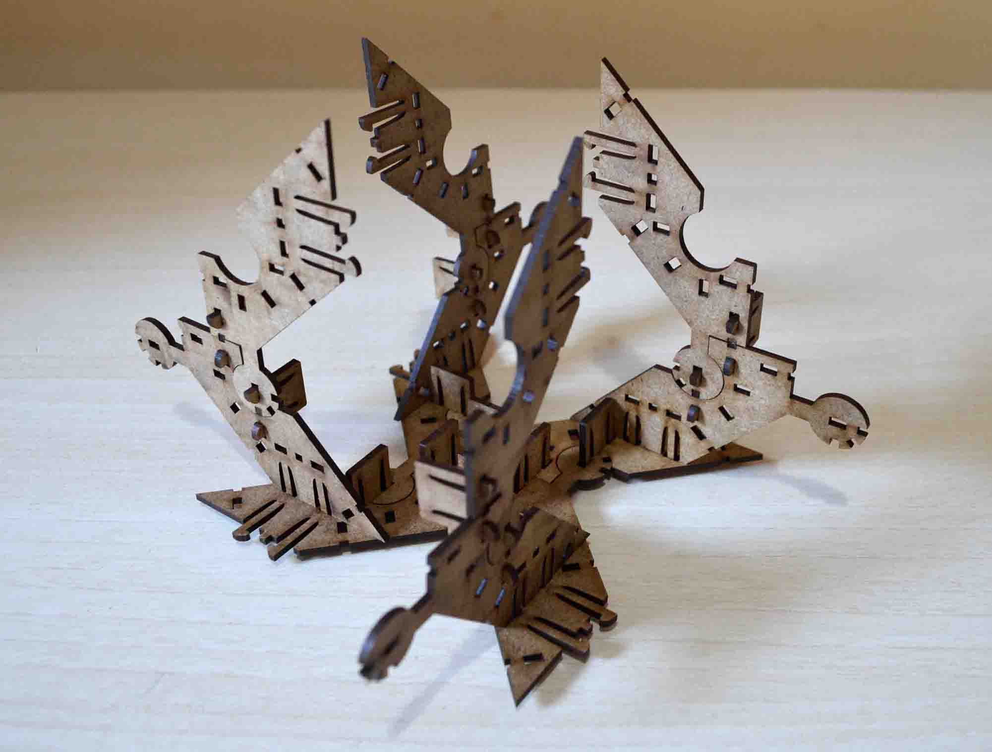
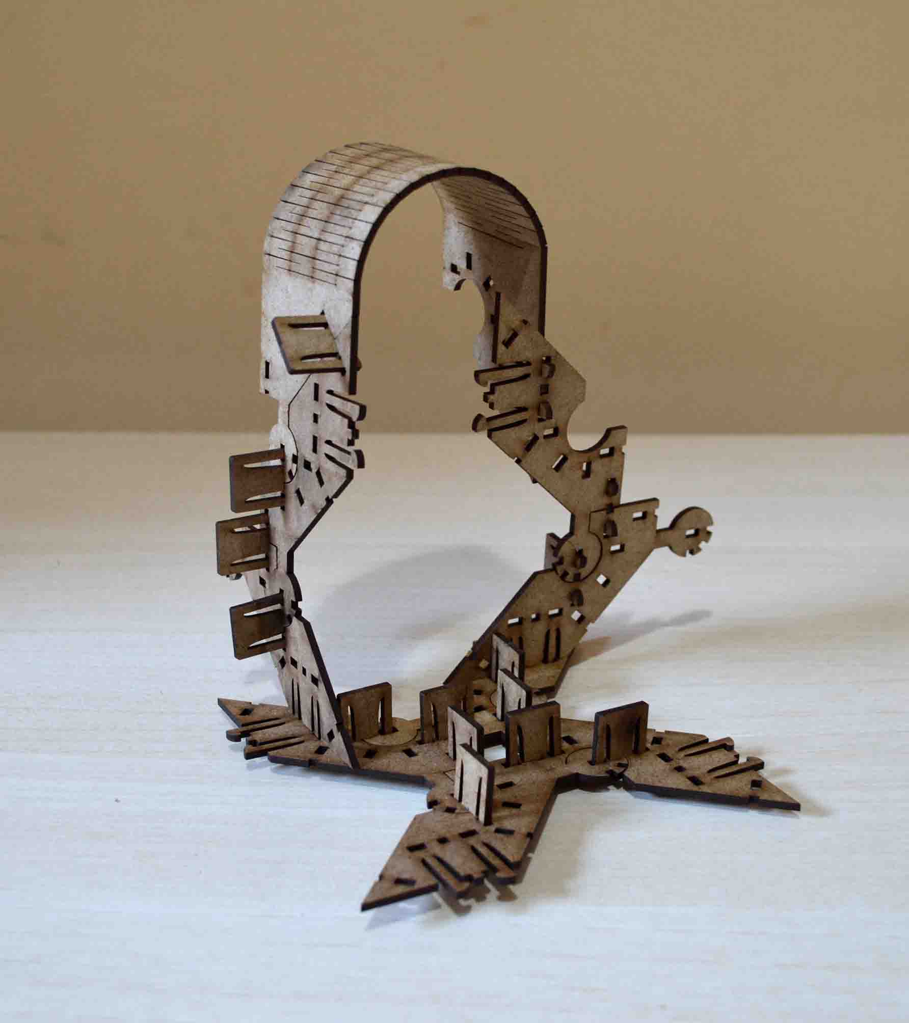
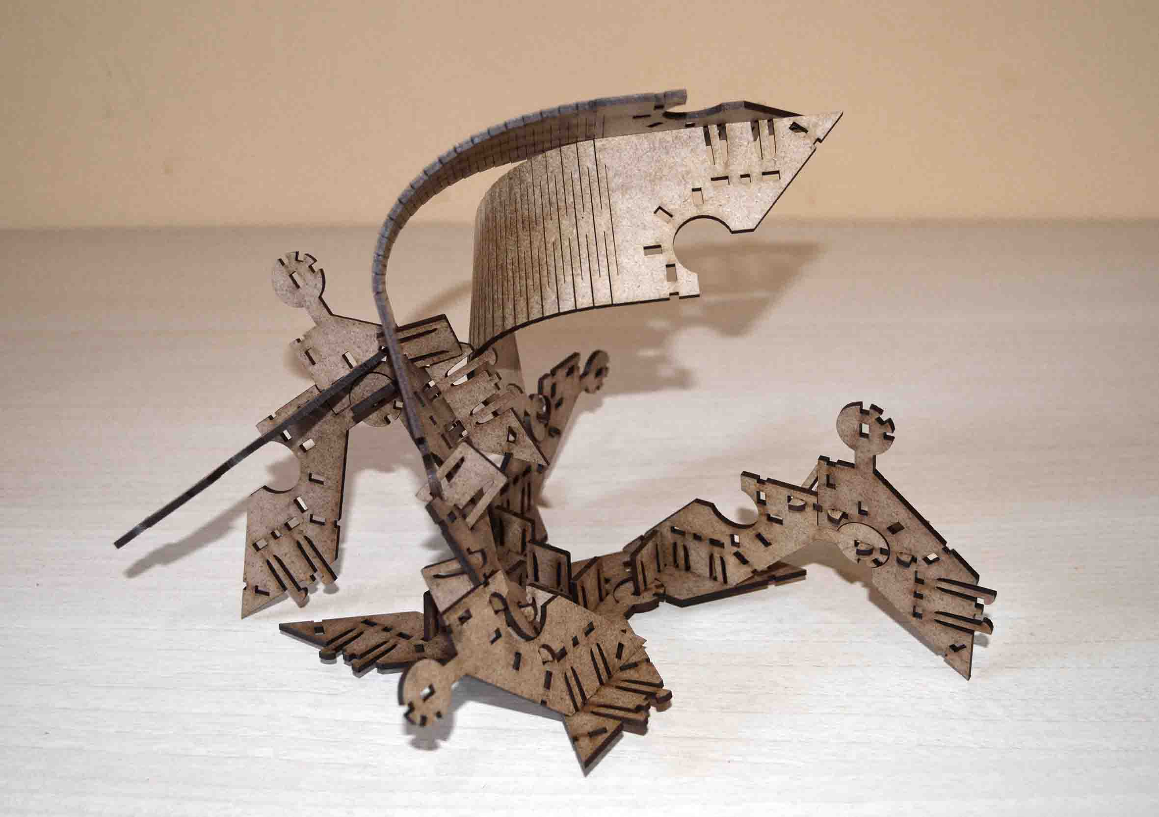
Playing with the pieces turned out to be surprisingly interesting. These examples are not exhaustive as I am still discovering possibilities and nice ideas about how to assemble my kit.
Vinyl cutter
A vinyl cutter is a computer-controlled machine that is used to cut out shapes and letters from sheets of thin vinyl. It looks like a computer printer, only instead of ink its head controls a sharp blade. The cutter is capable of moving the blade on an X and Y axis over the material, cutting it into any shape imaginable. A vector based design is created in a software program (usually Adobe Illustrator, Corel Draw or InkScape) and then sent to the cutter where it cuts along the vector paths laid out in the design.
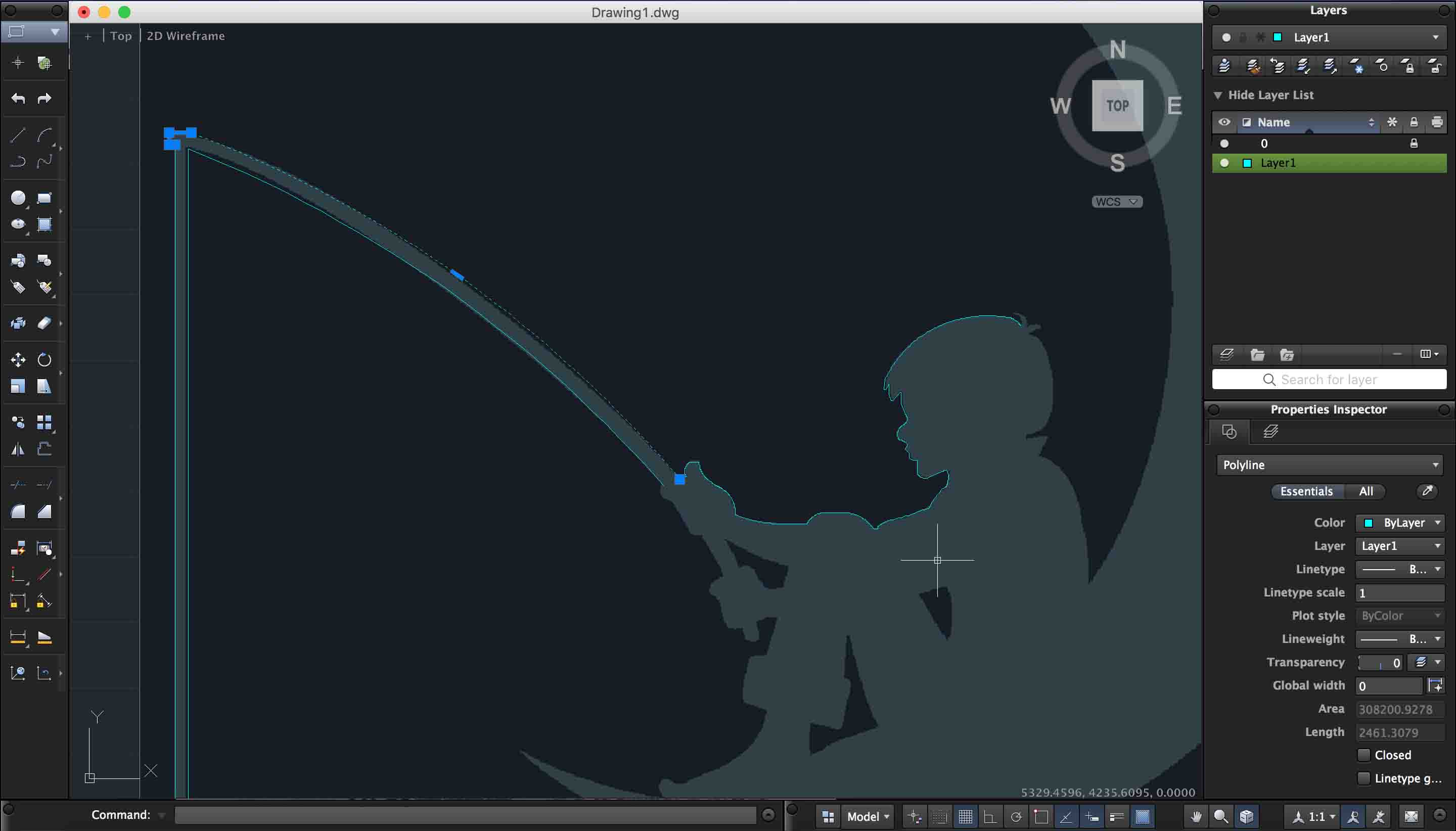
To experiment with the Vinyl cutter I decided to make a sticker for my laptop. I wanted to try cutting out difficult shapes with a lot of detail and thin lines, so I found online a design that met my criteria. Plus it stimulates playful memories from my childhood ;). Here you can find the initial image I used to make this sticker.

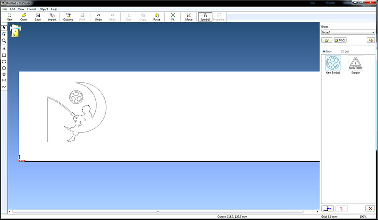
I inserted the image as an external reference (xref) on AutoCAD to draw over its lines. I didn’t choose illustrator for this job, even though I am quite experienced with it, because I recently discovered that for drawing over lines of images, using AutoCAD makes the task 5 times easier. I then exported the file from AutoCAD in .dxf and inserted it in illustrator to achieve the .ai extension, which is one of the file types compatible with the cutter’s software.
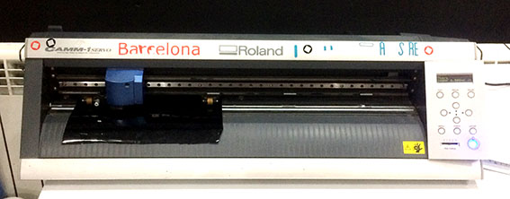
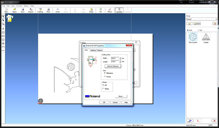
The software I used to send the file to the Vinyl cutter was CutStudio, and the machine was the Roland GX-24. The size of the Vinyl Sheet was automatically measured by the machine and imported in CutStudio. Then all I had to do is make a test to ensure that the blade is properly placed, check that the scale of the drawing was correct, and send the file.
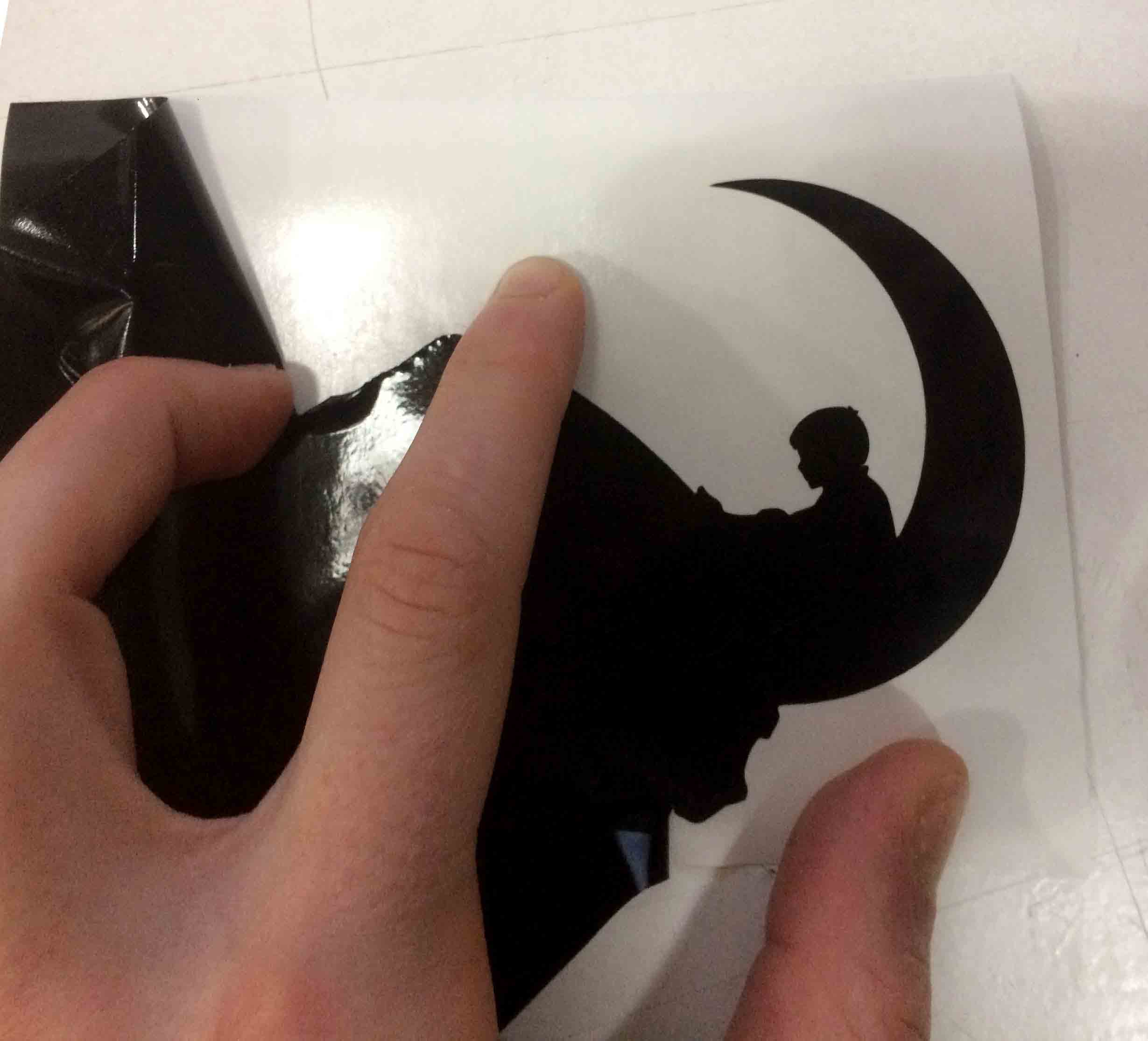
I cut the shape in black vinyl, and then carefully removed the piece I wanted. Even though the design has a lot of thin lines, none broke, and I was able to put it on my laptop from the first test. This shows both that the calibration of the blade of the cutter was correct, and that the quality of the vinyl was good.
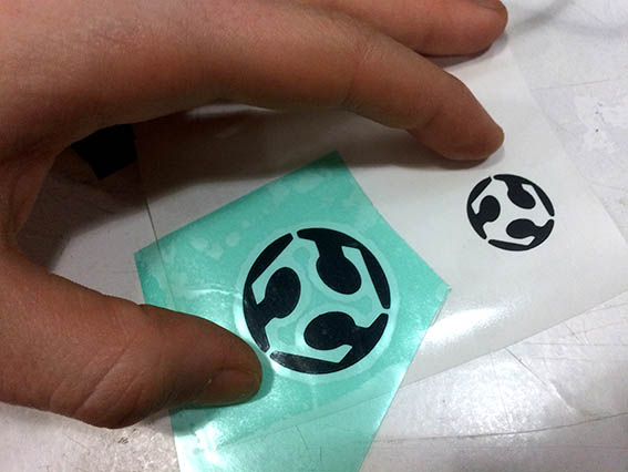
Here’s what it looks like now.
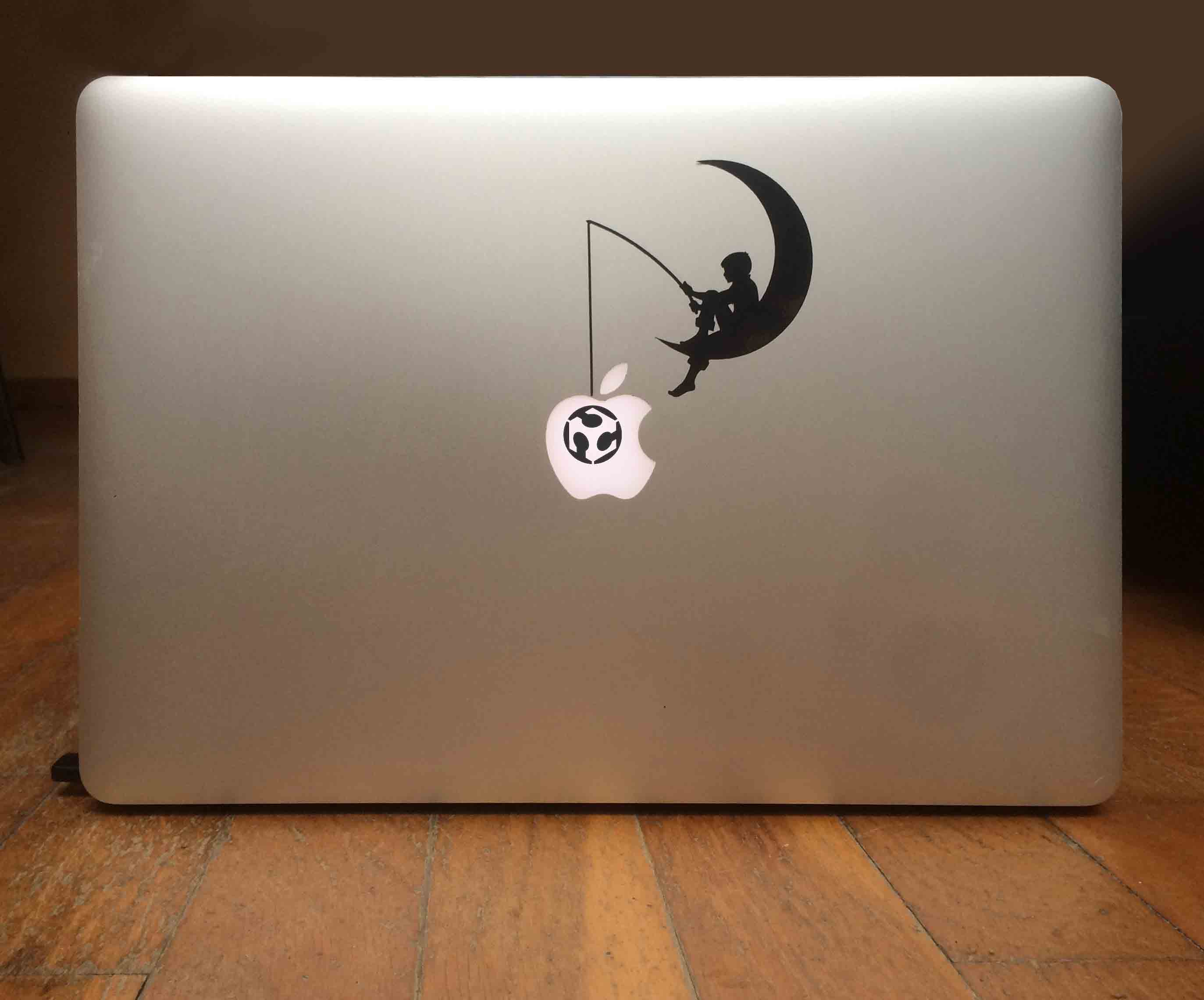
If you want to make the same vinyl sticker, you can download the file here