Barcelona is a wonderful city for cycling.
The city's mild climate and relief are ideal for everyday bicycle use. 80% of the city has a gradient of less than 2% and you can get around comfortably. The city has more than 140Km of bicycles lanes and everyday more than 140.000 bicycle trips are made ( source: Barcelona City Hall ).
-The Problem-
Barcelona contamination remains above the recommended values and this is a BIG problem for all of us.It is also a recurring problem in every big city.
-The Goal-
I wish I could resolve the pollution problem but I can't. The goal is to get a map of the city with the pollution level(environmental and noise) in real time. With a web platform or an app, any rider could know the least contaminated route to your destination.
-How-
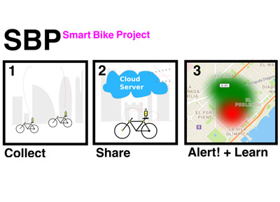
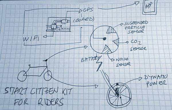
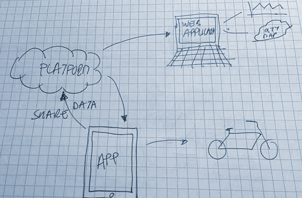
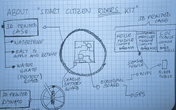
I've decided to make Smart Bike Project to alert the pollution that we suffer in the big cities. Here some sketchs:
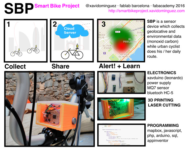
And the project slide:
It is divided in 3 parts:
- A sensor device that collects geolocation and environmental data (monoxide carbon in this version), while the urban cyclist make their daily route.
- Also a mobile application connects to the sensor (via Bluetooth) and upload the data to a database on a server in real time (monitors sensor data and the location of each minute).
- Finally there is an application website where you can see the most polluted areas of the city.
So the idea is to collect data, share, learn with this information and alert society to the problem we have.
Technically I've used different technologies:
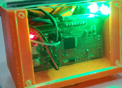
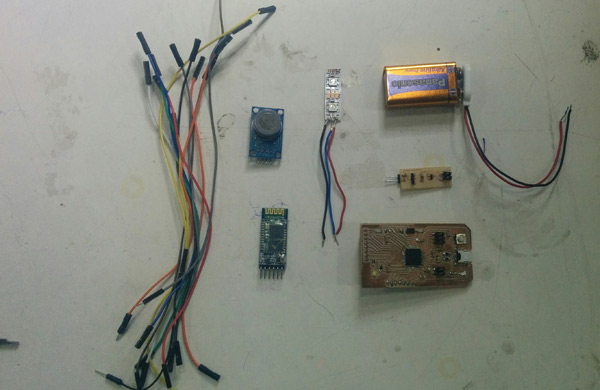
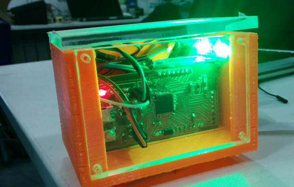
- For electronics, I designed a board based on Arduino Leonardo and a power supply for giving autonomy.Also the device has an airquality sensor module (MQ7 Pollution (carbon monoxide)), a bluetooth module for the communication between the app and the sensor, and 2 RGB (LEDs) as a signal for the user.
Designing the electronics I decided to make different boards and modules for each one to prevent mistakes during the process.
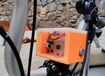
- For the mount bike support and casting I've used 3D printing and Laser Cutting. 3 pieces ( acrylic )
- For programming, I've used:
+ php and javascript, to load data MapBox GeoJSON.
+ sql for the connection to the database.
+ App Inventor for the Mobile Application.
+ Arduino for the electronics programing.
It's the first version of the project and for the next iteration I'm working to put all the electronics in the same board and make the device smaller, make a more "pretty" design and a better user interface for both the Application and the web.
Finally, I think it's a project which could be integrated with other initiatives such as intelligent citizen.
I have some experience developing projects with agile methodologies. Although this kind of methodoloies are thought for team developers I've tried to follow them for my final projects. Basically, I've used 2 online tools:
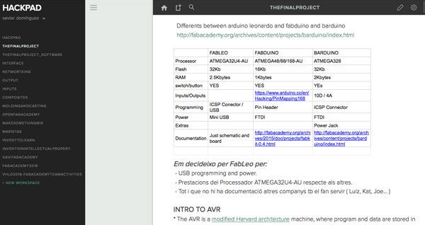
1_HACKPAD
Hackpad is a simple tool to capture, organize and share knowledge. I used Hackpad for document the project during the process. I love it because is super easy to use, it's in the cloud and can be access by ypur computer, mobile...
I did 2 hackpads: one for the hardware, electronics and 3D design, and one for the software part of the project.
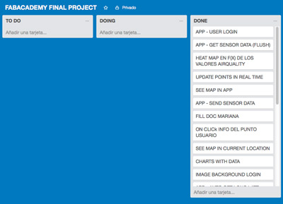
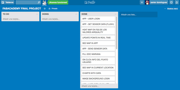
2_TRELLO
Trello is a collaboration tool that organizes your projects into boards.
I did 3 boards for the final project:
1. Things TO DO
2. Things I'm DOING
3. Things already DONE
It gives you a quickview about the project status.
3_QUESTIONS / ANSWERS : Project Progress
** what tasks have been completed **
1. Define the idea, search for references.
2. Design and make an electronic device for the first prototype with different modules.
3. Design and make a 3D case and mount bike for the first prototype.
4. Design and develop an application database.
5. Design and develop a heat-map from the pollution sensor values.
6. Design and develop an android mobile app for the first prototype.
7. Document during the process.
8. Get data from a pollution sensor ( monoxide carbon ). ** what tasks remain? **
0. Iterate for a second version of the project.
1. Integrate all electonic modules in 1 electronic board.
2. Make a small device for riders.
3. Re-design user interface ( web + mobile app).
4. iOS app.
5. Get data from different sensors ( sound and particles). Now only monoxide carbon sensor.
6. Improve web map with data by users.
7. Implement an algorythm with the "LESS POLLUTED ROUTE" for a rider.
8. New mobile app functionalities. ** what has worked? what hasn't? **
1. I've worked in the electronics design but not in an optimized design of the device designed for bikes.
2. Also I have worked in calibrating and get pollution sensor data but I have not done a thorough understanding of what the data mean and how to interpret scientifically.
3. I have not worked out how to integrate the project into other platforms. ** what questions need to be resolved? **
1. From the rider point of view... How I can know which routes are the least contaminated ?
2. How I can display more information on the maps ? (users, data values, charts...)
3. How can the project be integrated in other platforms like Smart Citizen ?
4. How to integrate all the electronics in a single device, small and designed for riders ? ** what will happen when? **
Once I have passed all FabAcademy I'd like to make a second iteration of the project where solve questions are pending.
In addition I would make a campaign crowdfounding to determine the degree of acceptance of the community. what have you learned?
1. Focus on the things that really matter in the project.
2. Manage time well to achieve a goal , even if it is minimal.
3. Electronics! Eagle! I think I can manage know for make more complexed boards.
4. Solidworks !
5. Mapbox ! Heat and data maps.
NOTE: All files all the project available in the "DOWNLOADS FINAL PROJECT" menu.
0_INTRODUCTION
For electronics, I designed a board based on Arduino Leonardo and a power supply for giving autonomy.Also the device has an airquality sensor module (MQ7 Pollution (carbon monoxide)), a bluetooth module for the communication between the app and the sensor, and 2 RGB (LEDs) as a signal for the user.
I already commented electronics in the Networking and Communications assignment.It's a resume.
1_XAVDUINO
Thinking on my final project I need a board with many inputs and outputs pins for connecting and communicating:bluetooth module, sensor module, some LEDs and a power supply.
Also a powerful microcontroller, ATtiny maybe will not be enough.
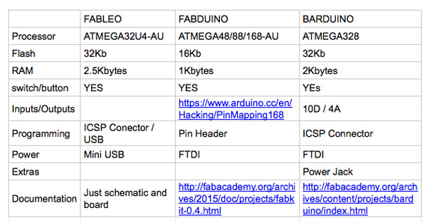
So I decided to make an arduino board, but which one? I did a table comparing the different options.
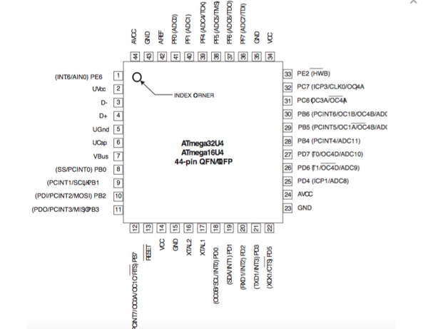
Finally I choose to based my design in FABLEO because:
1. I don't need an FTDI cable, just a micro-usb.
2. ATMEGA32U is better than the others.
3. Although there is not much documentation available , other colleagues also have used it and if I need help they will help me.
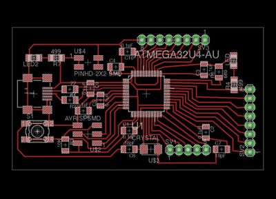
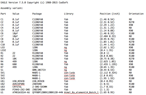
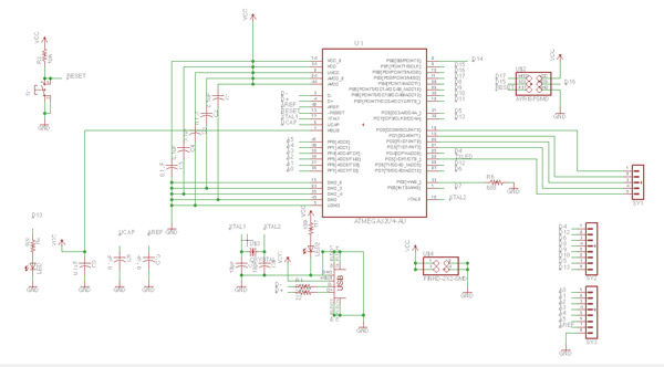
As always I did the design in Eagle.
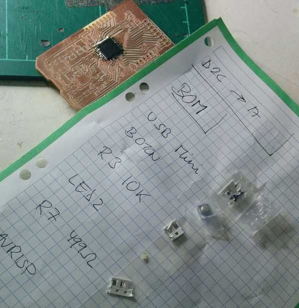
List components I used (available in download files):
I did some changes to the original fableo board:
1. I did it smaller. Removing some leds I didn't use and changing digital inputs position to the top.
Also I added some new inputs because I need use TX and RX pins from the ATMEGA32U.
I kept switch button and 2 LEDs integrated in the board becaused I'll use it for the programming.
In the schematic I hadn't any special problem.
The final schematic
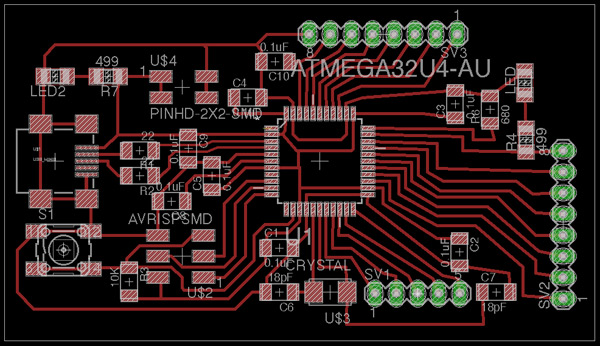
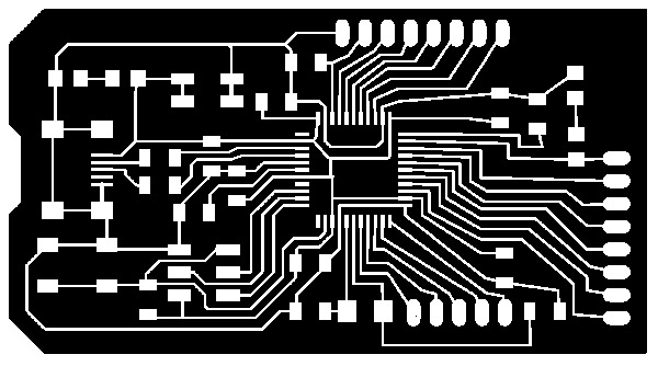
But in the board design I had some problems with the traces. It was not easy to make a "small board", enough width tracess and pass the DRC check process.
At least I managed but in future iterations I had to make it smaller.
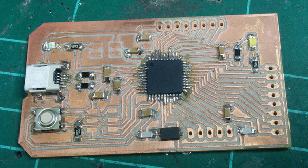
The final board - XAVDUINO
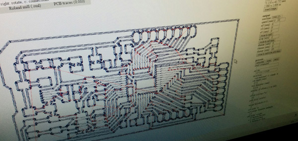
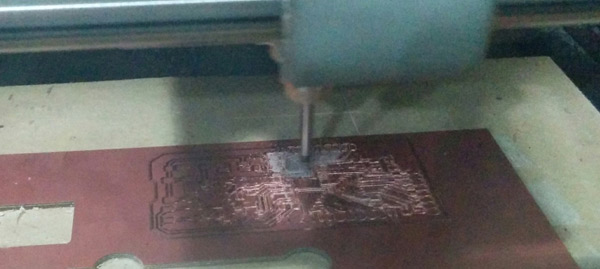
3_MAKE THE BOARD
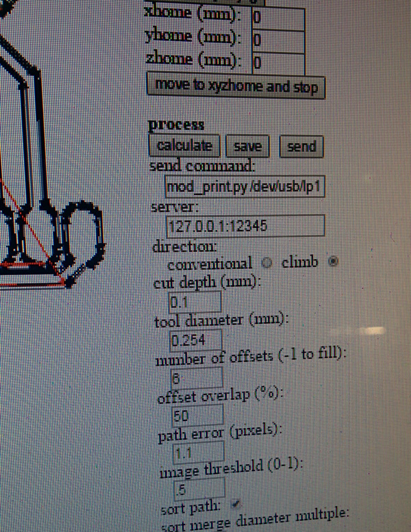
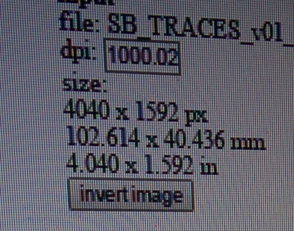
As always I used fabmodules and Roland SRM-20 machine.
I had one problem milling XAVDUINO: making the holes with the 1/32 milling bit you need to use the "INVERT IMAGE" option. It make holes inside and not outside (big).
I had to repeat the milling process.
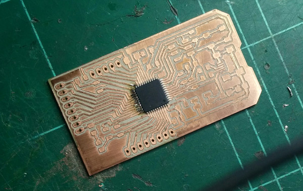
Soldering the XAVDUINO it wasn't easy but I managed.
For soldering the ATMEGA32U I used Flux.It makes soldering easier,soldered lead easily bonds on the copper pads.
After soldering I did the connections check with the tester and detect that 2 legs of the microcontroller weren't well soldered. I fixed it soldering again.
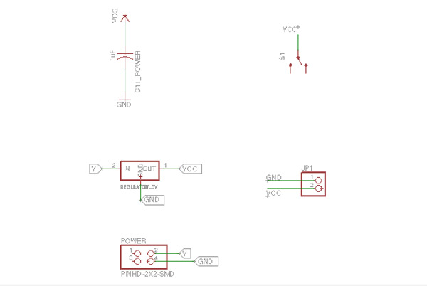
2_POWER SUPPLY
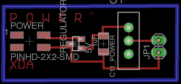
I also have designed a power supply board to give autonomy to the device. The design was simple adding a switch to turn off and turn on the device.
It's the schematic
It's the board
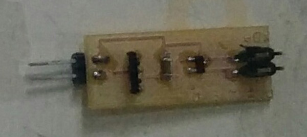
The power supply soldered and tested
I've used a 9v battery for power the Smart Bike device. I know it's not the best option for powering my device but in next iteration I'll try to use a LiPo battery connected to a dynamo.
Also integrate the power supply in the same device board.
NOTE: All files all the project available in the "DOWNLOADS FINAL PROJECT" menu.
0_INTRODUCTION
For programming, I've used:
+ php and javascript, to load data MapBox GeoJSON.
+ sql for the connection to the database.
+ App Inventor for the Mobile Application.
+ Arduino for the electronics programing. I already commented programming in the Networking and Communications and Interface assignments.It's a resume.
I used my fabisp as a programmer and Arduino IDE tool to do the bootloader.
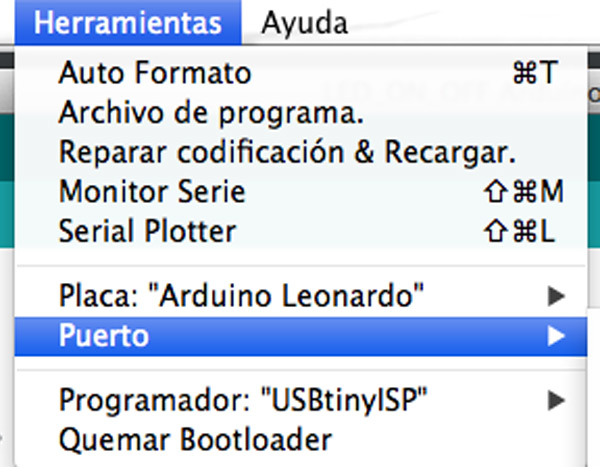
In Arduino IDE top menu choose Board->Leonardo and the USB port.
Then choose USBtiny as a programmer
Connect the XAVDUINO to the usb port
Burn bootloader.
I had no problem but for testing I upload BLINK sample to XAVDUINO and it worked!!
BLUETOOTH MODULE
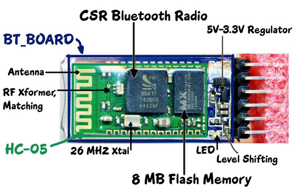
For the communication I used the JBtek-HC-05 Wireless module
Some information about this module:
1. Bluetooth module HC-05 Master and slave->Two in one module
2. Use the CSR mainstream bluetooth chip, bluetooth V2.0 protocol standards
3. Module working voltage 3.3 V
4. Potter default rate of 9600, the user can be set up
5. The core module size : 28 mm x 15 mm x 2.35 mm
6. Datasheet
Now it's time to configurate the bluetooth module.
I use XAVDUINO board for the configuration connecting it to my computer and uploading an empty sketch. void setup(){} void loop(){}
Then connect Rx/Tx pin XAVDUINO to Rx/Tx of bluetooth module.
Also 5v XAVDUINO to VCC HC-05.
GND XAVDUINO to GND HC-05.
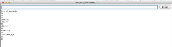
Now use the SERIAL Monitor of the Arduino IDE to feed AT commands.
At the bottom of the SERIAL monitor ensure that you select “BOTH NL & CR”.
Type in AT+click on Send.
You should get a OK response from the module.
1. SLAVE mode.
The slave modules can not initiate a connection to another Bluetooth device, but can accept connections.Master module can initiate a connection to other devices.
By default ROLE of HC-05 is SLAVE.
Type AT+ROLE to confirm it.
2. PASSWORD: AT+PSWD to know the password. By default is 1234
3. AT+UART to Baudrate
4. AT+NAME to change the name
Now it's time to programm a mobile app for the comunication between XAVDUINO and my mobile phone.
2_APP INVENTOR
I already had experience programming with App Inventor.
It's visual, blocks language for building Android Apps and also for learning programming.Build apps is very fast with this great tool.
I'm part of the Vailets Hacklab group. We make events and workshops for kids and I use App Inventor to teach programming.
How I did Smart Bike Project App?
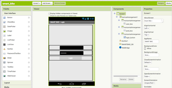
1. FRONT END APPLICATION
First, design user interface of the app with the App Inventor Designer Smart Bike Project - Log in screen
SmartBIKE_DB -> Local Database for recording sensor data in the mobile.
WebBridge -> HTTP connections to a server database for user verification.
Buttons -> UX Smart Bike Project - Data screen
Bluetooth Client -> Use Mobile Bluetooth chip for connect the app to the smart device.
Location Sensor -> For get geolocation data.
Clock -> For request sensor data each X seconds.
Web -> Show maps for the mobile user (under development).
Buttons -> UX, Select Bluetooth Device. Sensor Value -> Print the value of the enviromental sensor Background Color -> It changes depending the value of the sensor (green, orange, red) 2. BACK END APPLICATION
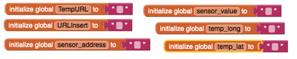
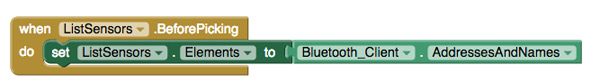
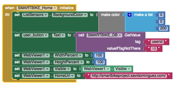
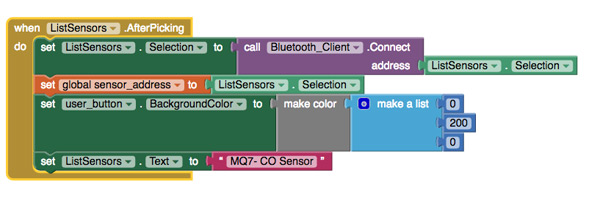
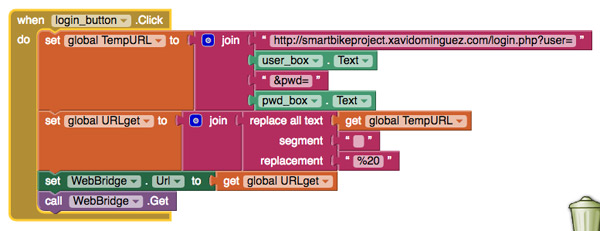
For the back end programming you have to use the App Inventor Block Editor.
It's the part that connects with the bluetooth module, the cloud server, php gets.
Global variables
Get a list of the bluetooth nearest devices
Initialize Data Screen (map, user name, data sensor value and background,bluetooth devices...)
Bluetooth connection
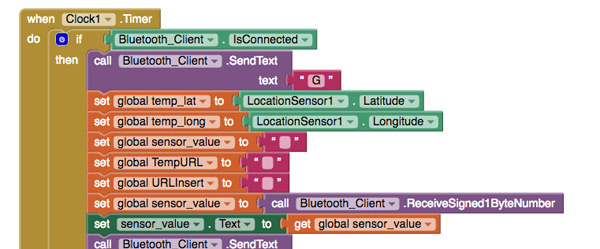
Check if bluetooth from the device is available, get geolocation data (long, lat),initialize variables,get sensor value from the device and send confirmation
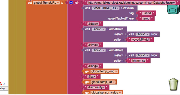
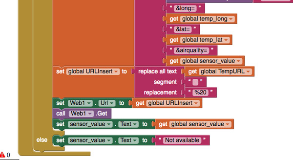
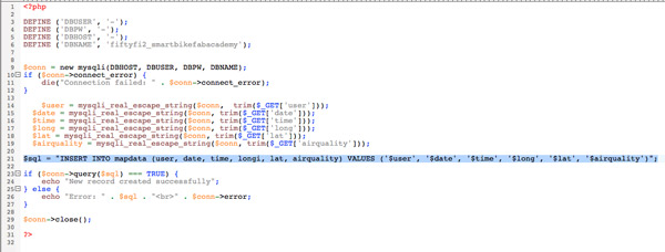
Insert data in the Database Server calling a .php file (insertData.php) which executes a insert query.
Print data in the mobile interface, change color or alert user bluetooth device is not available
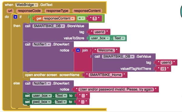
User verification process
Save information in local database
3. DEMO
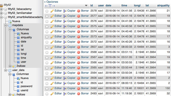
3_MySQL: DATABASE
You can go to the web application with this link. In a server I created a Smart Bike Database in a MySQL system. (available in download files)
I insert, update, read data with sql queries. It's an example of the data stored and database structure.
Insert data php and query example
Note: All files available in download files
4_WEBAPP: MAPBOX+JAVASCRIPT+HTML5+PHP+GEOJSON
For visualize data from the sensor I developed a Web Application available here (webapp code available in download files)
I've used: MAPBOX + GEOJSON Mapbox is the mapping platform for developers.
I tried other platforms like CartoDB or API Maps Google but I think Mapbox is the best option because they have availiable libraries for developers in different languages like javascript (great for me!), python...also a lot of documentation and a big developers community.
How it works : Design a map, add data, programming it, upload to a website.
All you need to start using Mapbox is an access token.
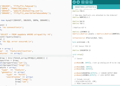
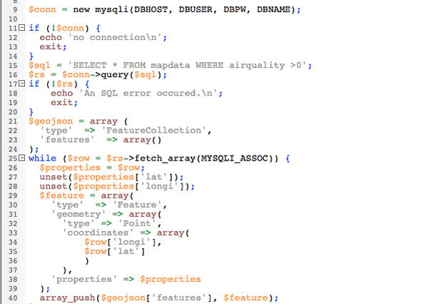
Before adding data to the map I convert it (php) to GeoJSON. GeoJSON is a format for encoding a variety of geographic data structures. In my case: user id, lattitude, longitude, airquality (sensor value)
How I did it? Code comments:index.php
Read data from database and transform to GeoJSON format
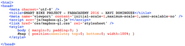
Import Mapbox javascript library and map style
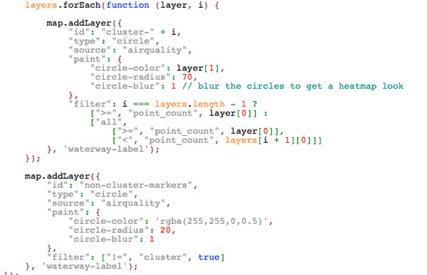
Initialize map with javascript, read TOKEN and add data to the map
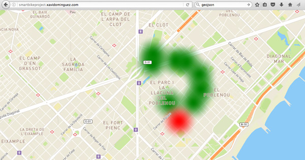
Add points to the map and paint heatmap color depending of sensor values DEMO
Note: Red area is near the FabLab where I got more values so the device was more precise.
NOTE: All files all the project available in the "DOWNLOADS FINAL PROJECT" menu.
0_INTRODUCTION
I've used Soliworks for the 3D design, Formbytes for the 3D printing(case) and Epilog for Laser Cut (top and right case)
1_3D DESIGN AND 3D PRINTING
Definetely, Solidworks is my favourite 3D soft when you design a product. It can be parameterize, very accurate and easy to assemble all parts in a 3d objet for 3d printing.
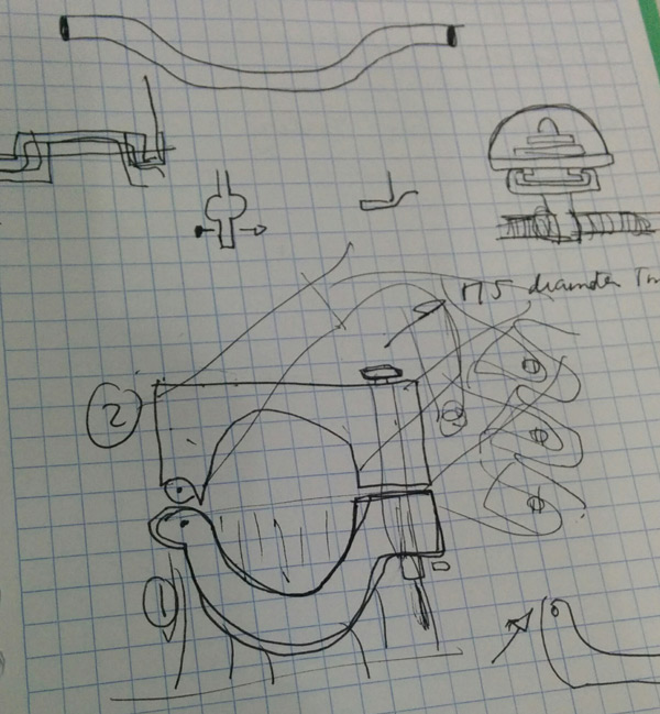
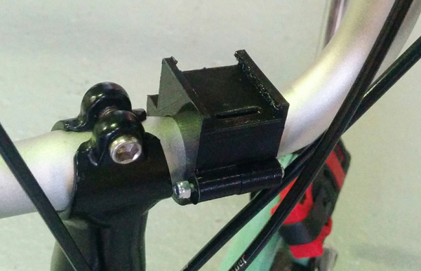
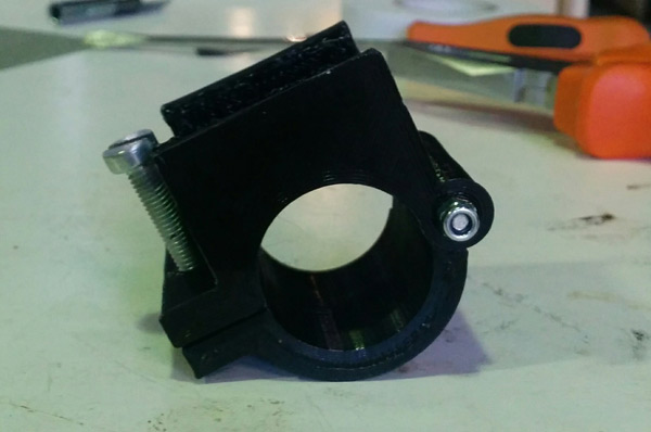
I started designing a support for the handlebar bike.
Some drafts.
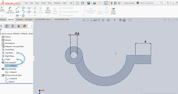
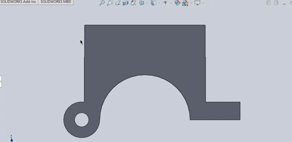
In Solidworks, first I design the shape (parametric)
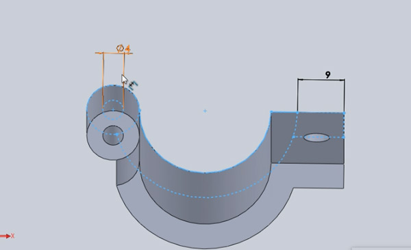
And then I use the extrusion tool
Also I added a hole to tighten the piece to the handlebar with a screw.
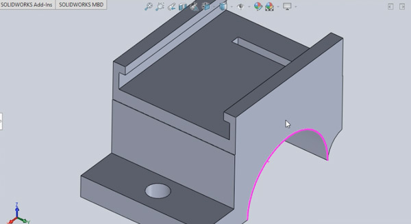
The same for the top part
Here you can see the top view with the join for the device case.
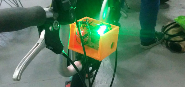
It's the design of the case where the device will be inside. It has a space for fixing the board, a hole for the sensor and holes for fixing the acrylic.
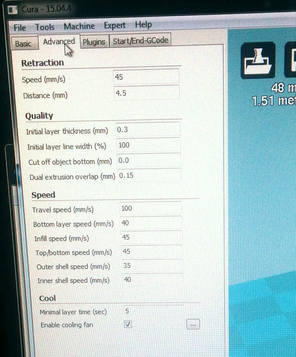
I used Formbytes machine for the 3D printing.
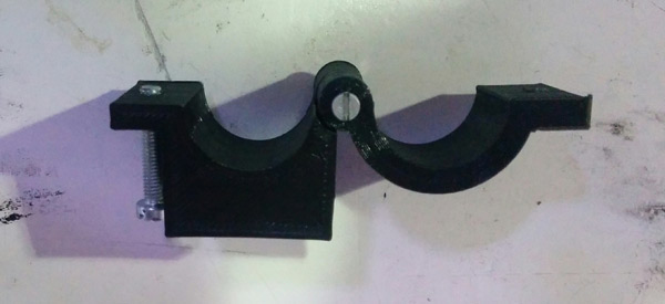
First, prepared GCode with Cura Software and then imported it to the 3D printer.
The result
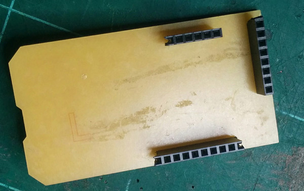
2_2D DESIGN AND LASER CUTTING
I used Inkscape for designing the top part of the case and then exported to Rhino for laser cutting.
In the laser cutting process first I did the engraving and cutting at final.
NOTE: All files all the project available in the "DOWNLOADS FINAL PROJECT" menu.
PRESENT
At this moment Smart Bike Project can:
1. Read monoxid carbon sensor.
2. Communicate the device with a mobile app.
3. Upload data to the server.
4. Show a heat map of the city pollution.
5. A case for the device mounted in a handlebar bike.
FUTURE
Next iteration:
1. Desing a small device.
2. Make a better product design.
3. Add more sensors: particles pollution sensor and a sound sensor.
4. Assemble in the same board all the sensors.
5. Assemble in the same board the power supply.
6. Improve user interface both: mobile app and web application.
7. Add charts and more data to the map.
8. Try to integrate it with the Smart Citizen project.
9. Show in mobile app an option to "find less polluted route" for the riders.