Design and build a wired and/or wireless network connecting at least two processors
This week’s assignment was to build a wired and/or wireless network connecting at least two processors. This is my first time making a network so i decided to start this week of by at least making the bus bridge and nodes from the archive site and then hopefully design my own network. Networking can allow me to send and receive information between individual growing units and a master controller. I think i wont use networking in my final project but i definitely could. I could have 1 master and 3 nodes, one for the buttons, one for the accelerometer and then one for the led. But i think that i would never fit all of these boards in the sabers hilt so i will probably make one board with all of these features.
Milling And Soldering The Boards
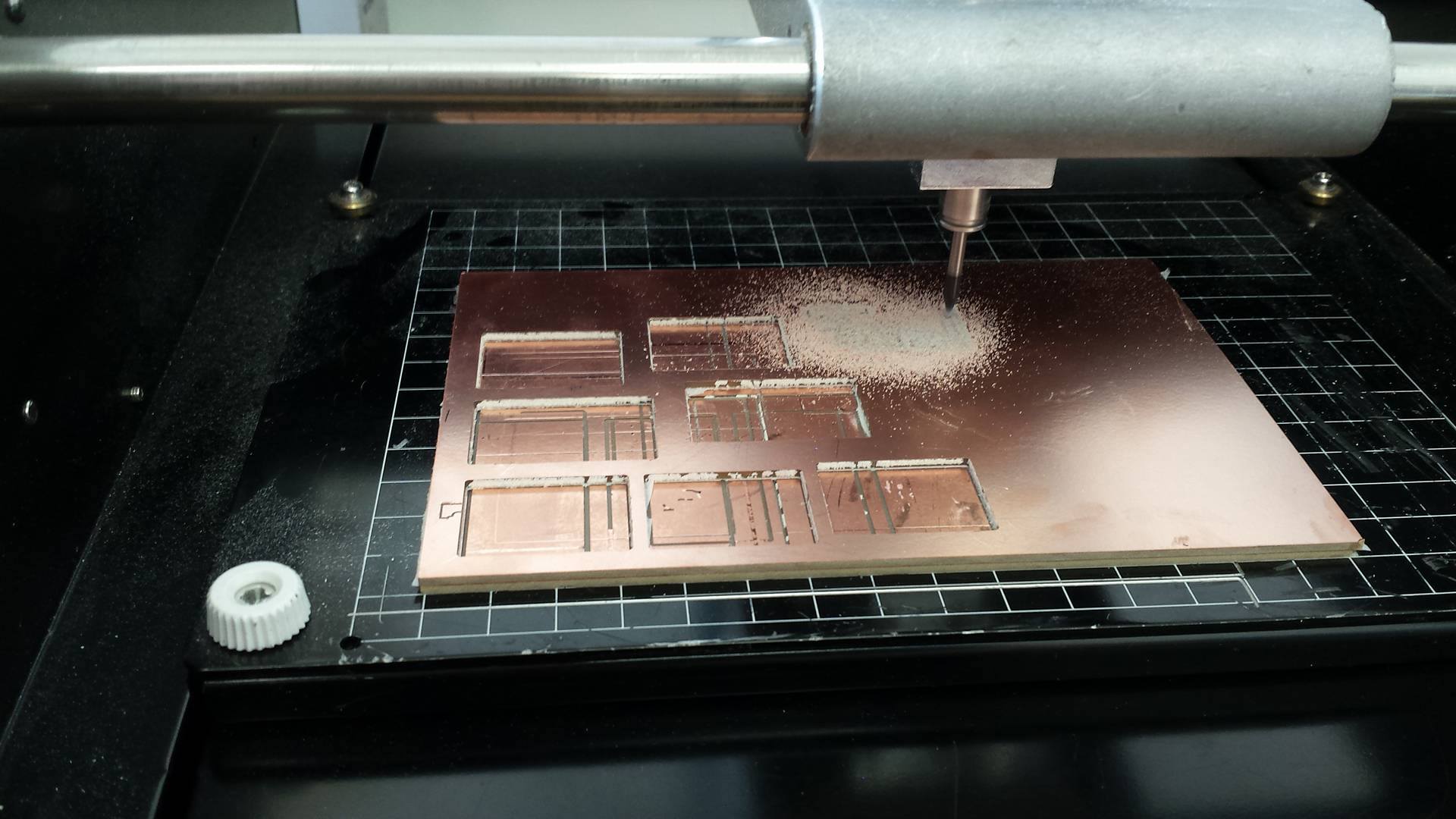
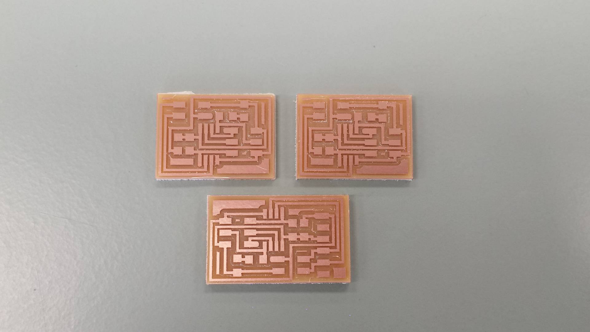
I got the traces and interior PNG’s of the hello.bus.45.bridge and hello.bus.45.node from the archvie and milled them out on the Roland modela milling machine. I made one bridge and three nodes, you can see instructions for the milling from week 4.
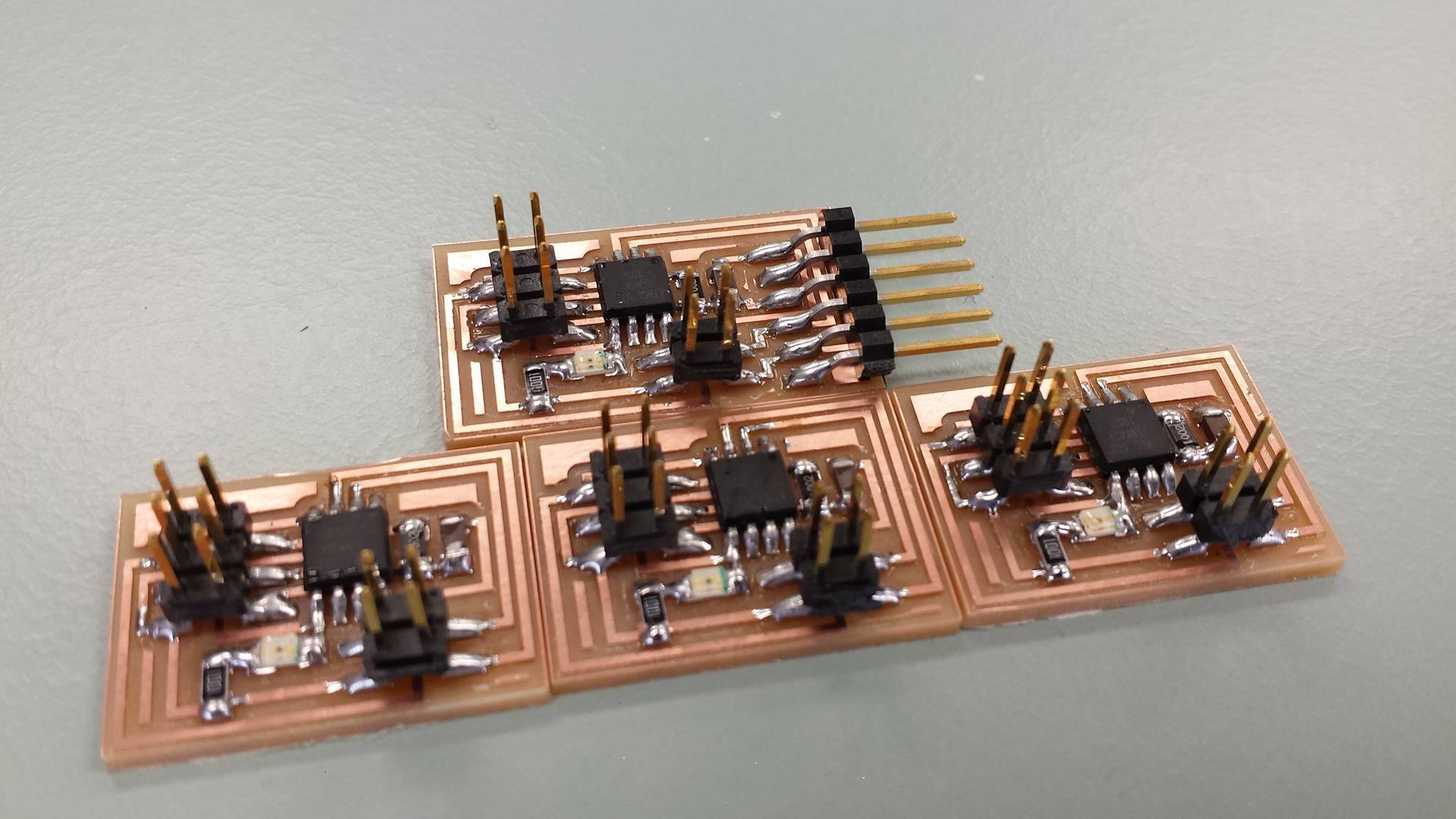
After the milling i soldered all the components to the boards and these boards are definitely the best soldering job i’ve done, i put red LED’s on all the boards except one node which got a green one. Then i connected all the boards to the AVRISP to check if they would work properly and thankfully i got a green light which means it works.
Programming The Boards And Testing The Network
Now i got the makefile and C file from the archive and saved them in a folder on the desktop. Because we need to give every board there own ID i had to edit the C code, to do that i went to the terminal and wrote:
gedit hello.bus.45.c
Then the text editor opened and i went to line 41 and changed the ID for every board, made the bridge 0 and the nodes got 1-3. Next i programed the boards by running the makefile and to do that i wrote:
sudo make -f hello.bus.45.make program-usbtiny
And of course if you’re using the AVRISP to program the boards you should write:
sudo make -f hello.bus.45.make program-avrisp2
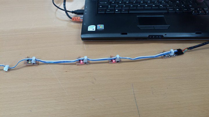
I was able to program all my boards without any problem so now it was time to run the python file but before doing that i went to the archive for input devices input devices and got a file called term.py. Next i all the boards together and the bridge to the computer with a ftdi cable and then found out that i was using serial port ttyUSB0. Now i ran the python file by writing:
python term.py /dev/ttyUSB0 9600
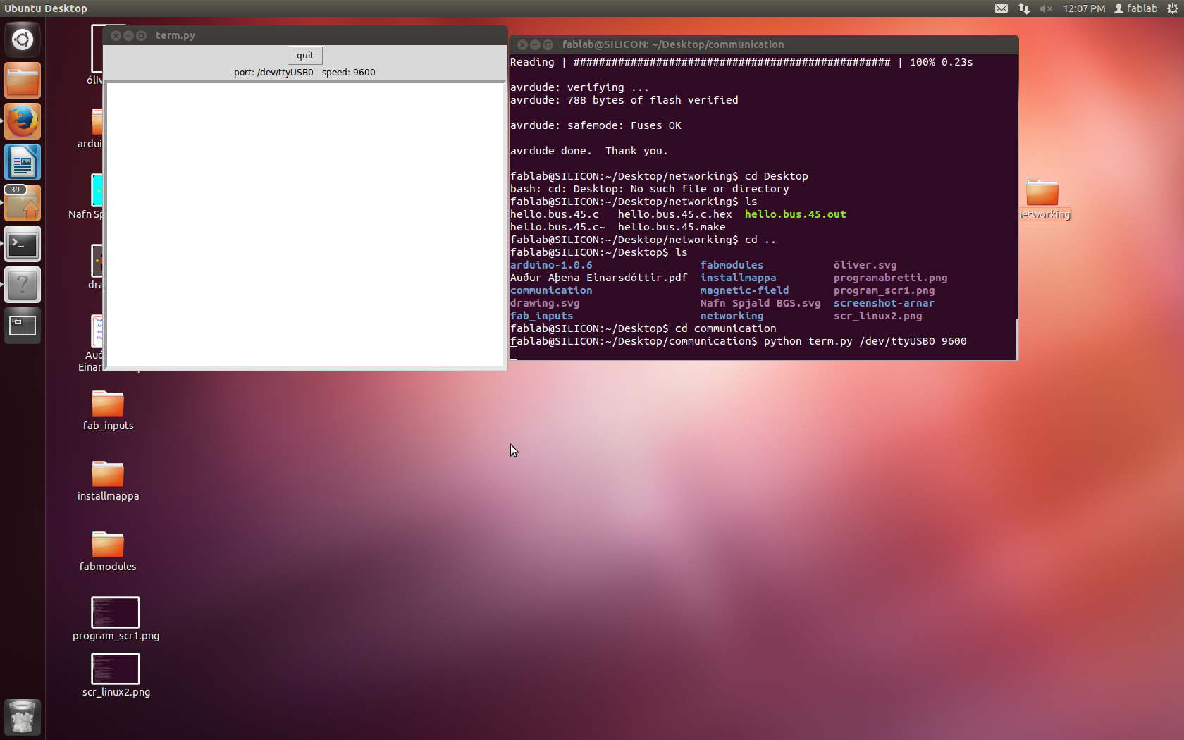
When i had done that a window popped up where i could write down a boards number and then all the boards would blink one time except for the board with the number i wrote, that board blinked twice. Here below you can see a video of the boards in action.
networking from Arnar Sveinn Guðmundsson on Vimeo.
Networking 2 from Arnar Sveinn Guðmundsson on Vimeo.
Files
Bridge TracesBridge Outline
Node Traces
Node Outline
C file
Makefile file