Redraw the echo hello-world board and add at least a button and LED with a current-limiting resistor, then check the design rules and make the board.
CS Eagle
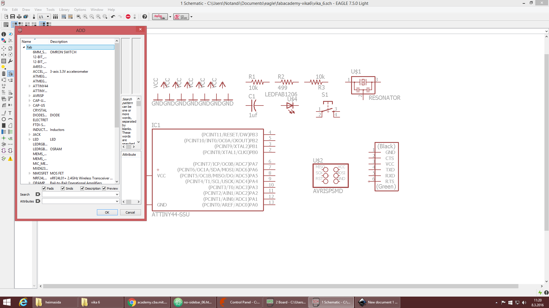
I decided to use CS EAGLE to design my board, i have had some experience with Eagle but Þórarinn from fab lab Ísafjörður and Daniel from fab lab WA taught me and two of my friends the basics on Eagle. I hope that i will also have time to get a look at other software like for example 123D circuits. i had already downloaded Eagle to the computer i was using. On their website it say´s “EAGLE or the Easy Applicable Graphical Layout Editor is a powerful PCB design software tailored to meet the needs of professional engineers, makers and those at school. The simplicity of the software provides a fast learning curve, even for those new to PCB design. The openness of EAGLE design resources, such as its extensive and fully-open component libraries, ease the design process for all. The first thing i did after opening Eagle was creating a new project and then i followed the instructions from the fab wiki site about CS Eagle which told me to open the library and turn off all the libraries and then only turn on:
- fab.lbr (i had to download this from the archive to the library file in Eagle)
- supply1.lbr
- rcl.lbr
- led.lbr
- v-reg.lbr
Schematics
In the schematics window i started off by adding the components i was going to use in my board design, i was only going to add one button and one LED. The components that i needed were:
- ATTINY44A-SSU-ND Microcontroller
- FTDI SMD header
- 20 MHz Resonator
- AVRISP 2x3 pins
- 1μF capacitor
- 499Ω Resistor
- 2x: 10KΩ Resistors
- Omron TACT switch 160 GF
- Led 1206 Fab style
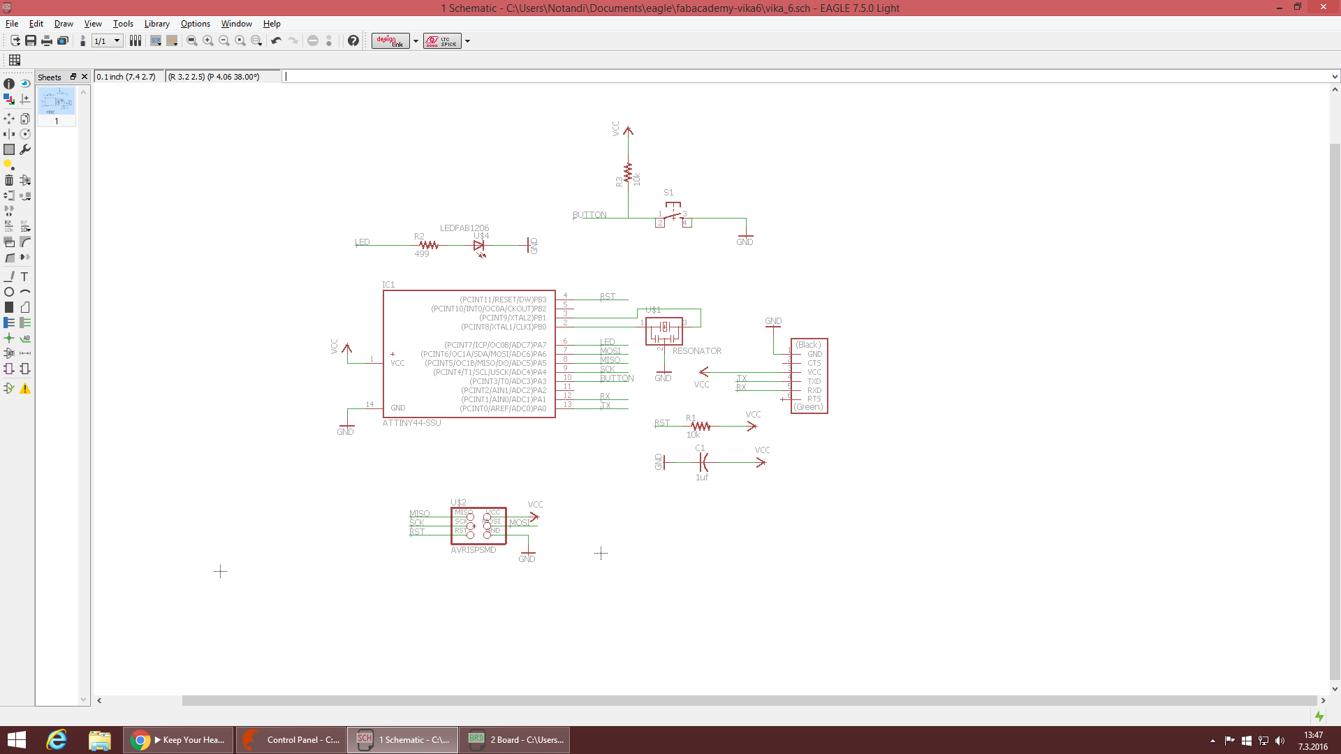
The next step was to connect the right components together with the wire button, and to do that i looked through some older project to an idea what it should look like. After everything was wired it was time to go to the board layout by pressing the generate/switch to board option on the toolbar.
Board layout
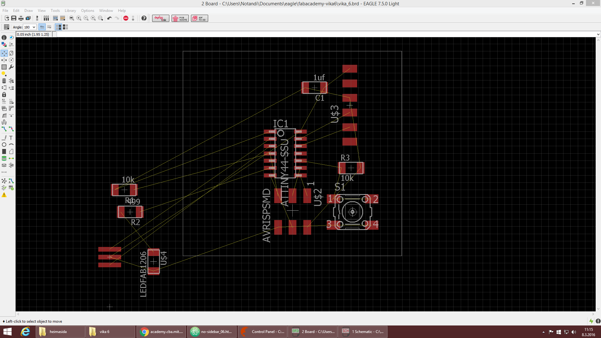
So after selecting the switch to board option a new window pops-up. Here i started to arrange the components to make the routing as easy as possible because the routing can be time consuming and a pain in the ass. After arranging the components the next step was to connect the components together, to do that i had to use the route function but that function creates ,like the name implies, a route between the components. Finally after a few trial and error attempts i was able to get the route to the right places without crossing over other routes.
After connecting everything i did a DRC (design rule check). Daniel had pointed out to me and my friends that the DRC from fab lab Wellington were really good so i used their´s to do the DRC for my board. The only problem i had was with the routes under the ATTINY they were a little bit too close together, so i made them all thinner than the other routes or from 0,016 to 0,012.
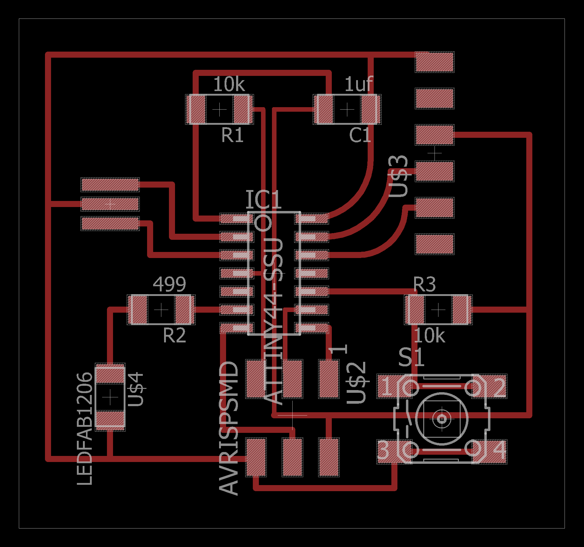
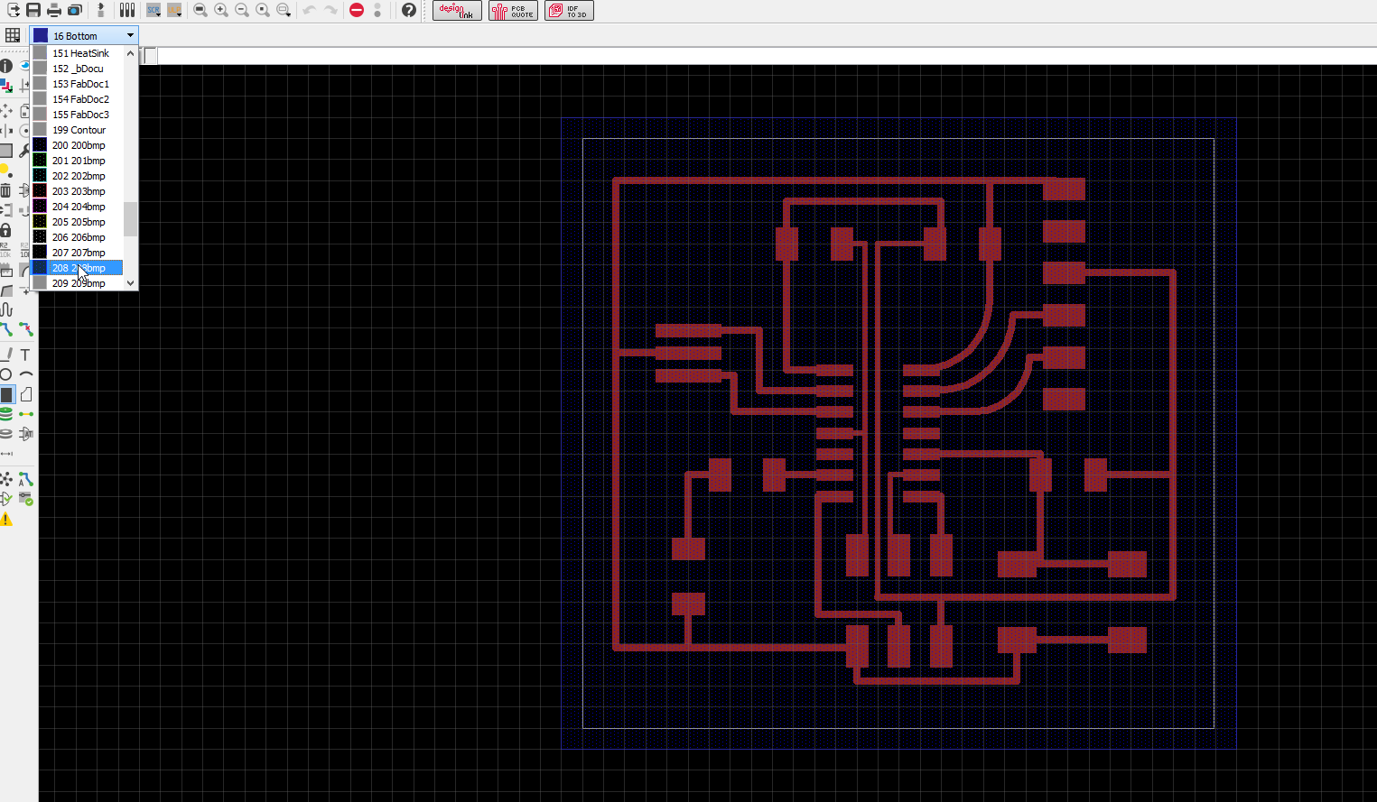
So now it was time to make the trace and board outline PNG´s. First i pulled the thin white line closer to the layout then went to the layer setting in the view menu. There i selected None and Apply and then i only selected layers number 1, 20 and 208 and applied them. Next i turned the grid display on and selected the Rect function, after that i selected layer 208 in the menu above and drew a box around the white box i already had.
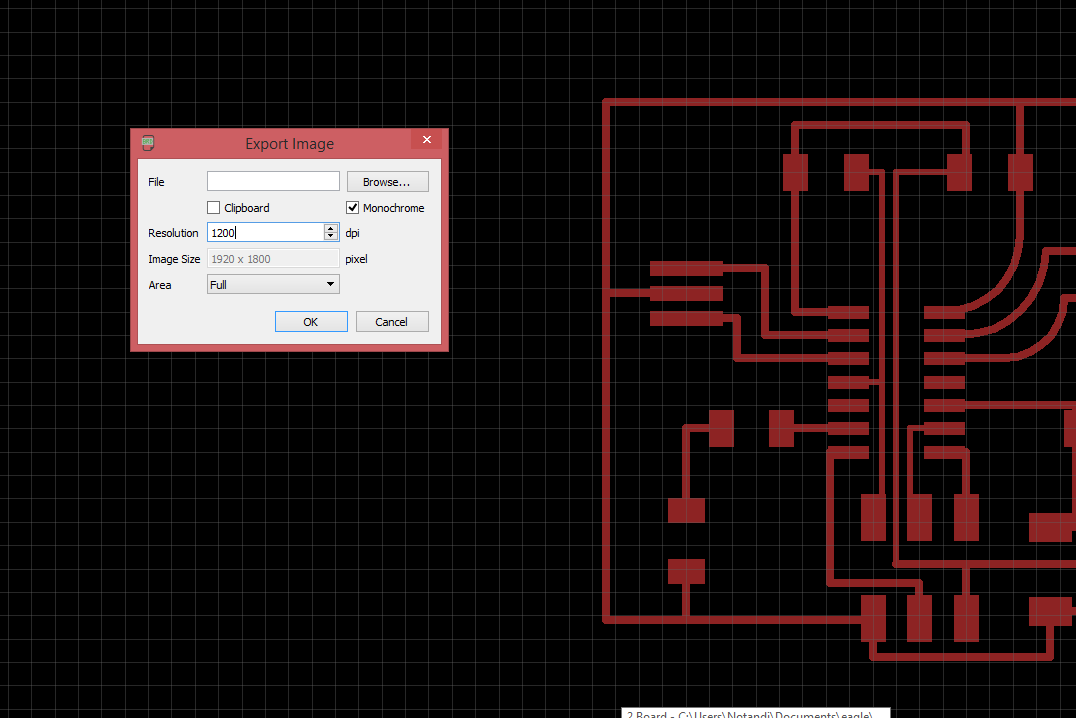
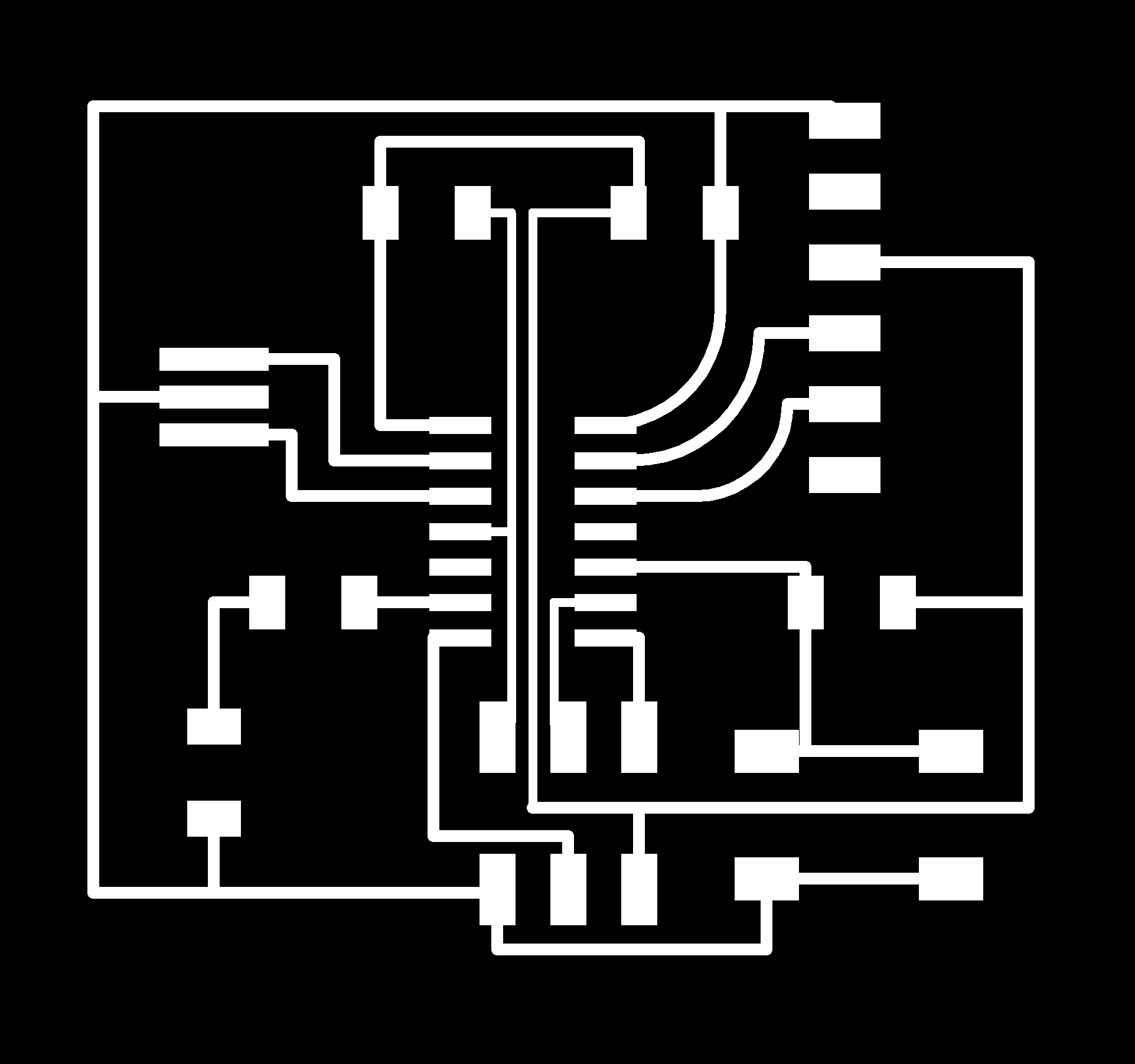
Next i went back to layer settings and turned off all the layers except layer number 1 with the traces. Then i went to File and export as image, and in that window i put 1200 in resolution and checked in the Monochrome box, and next i saved it.
After that i only selected layer 20 and did the same for the board outlines, but i had to open the outlines in Gimp and fill the inner box on the image with white paint and then save it.

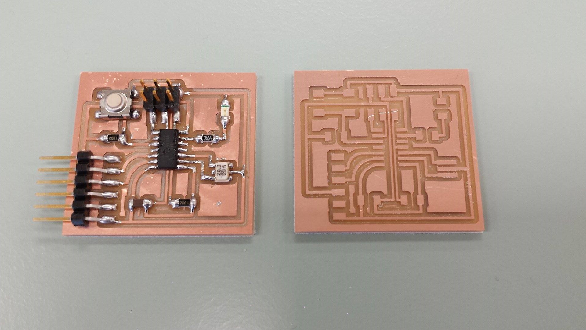
Now i was ready to mill out my board and ran into no problems on the milling machine. When the milling part was over it was time to solder the components to the board, i found it a little irritating soldering the resonator to the board but not a major problem. In the local meeting on tuesday Bas told us that the pull-up resistor for the button was not necessary because the ATTINY at one build in. And in the end i didn´t make enough time to try other software.
Files
Trace imageBoard outline image
Eagle Schematic File
Eagle Board Layout File