WEEK 4
ELECTRONICS PRODUCTION
WEEK ASSIGNMENT
Make an in-circuit programmer
I have to be honest, this has been a challenging assignment, I have no electronics background so I had to learn a lot of things in a couple of days. I definitely still have to learn a lot, however I believe that thanks to this assignment I’m now capable to understand basic concepts that will make easier for me to learn more complex things about electronics.

You can download the files HERE
THE PROCESS
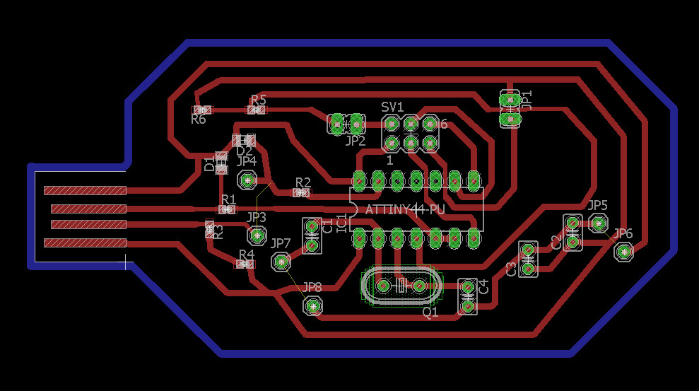
So the first step I followed to start the assignment was to understand how the circuit was shaped and the components within it; I used a diagram that I found in the webpage of a former Fabacademy student to start working. With this diagram I was able to understand how the board elements are related.
After understanding the board elements I had to design my own, for this task I used EAGLE a board design software. with this software you can work in 2 ways, schematic and directly into the board. I strongly recommend to start designing in schematic because once you start working in the board it's easier to connect the elements, the software can indicate you where to connect each part. That won't happen if you start working in board directly (that happened to me and was horrible :( ).
I also recommend to download different libraries, specially the fab library, it will help you to easily find all the components needed
What you have to do when using eagle is to find the elements no need in the libraries and place them in you canvas, once you have them there you can start connecting them as you need

1 - 2
<
>
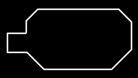
Once finished the boar design, you have to export it as a .PNG file, but before that is important to check out the active layers, and turn off those that you don't need, make sure that you have the contour trace in a separated layer because it will run as a different program.


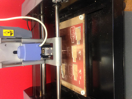
After exporting the .PNG file it's important to edit it I would recommend using Photoshop, the edition needed is a very easy task, is just changing the background color from white to black and the paths from black to white and on the other way for the contour file . Once having both pictures I used fab modules to make the paths code and run the Modela machine. First I imported the picture with the circuit trace, I programed the settings such as speed and depth, according to the tool used, in this case was a 0.4 mm drill.
I had to repeat this assignment 3 times due to some design mistakes.
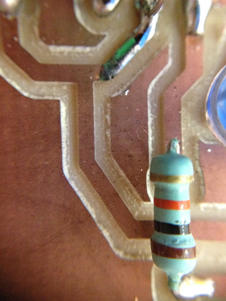
Soldering was also something new for me, I had to practice with some other materials before soldering my board. Once I felt comfortable with the process I started with the board, however is was more difficult than expected because the elements used were tinier that the ones I practiced with.