W19- Project development
Acrylic Pyramid
Pyramid Design
I use this template to make the design of the sides of the pyramid and transform it in fabable style with press-fit joins, and that 54 degrees angles.
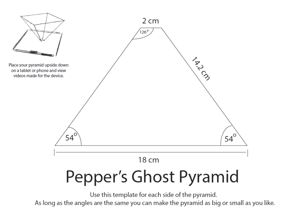
One trick for design the pyramid is make the maths and know the side of your pyramid, make a box in maker case with that side for example in height, and with the exported svg take that side, rotate to 54 degrees is is in the template. You have one side, replicate with mirror that side and you have the complementary side, then join up and down vertex and you will have one face.
You check with the template and then apply the kerf adjusts for your material and laser cut machine.
You can save the following svg image to have the design of the pyramid for laser cut and press-fit, you still have to make kerf fixing for your material. I use acrylic of 2mm and the kerf was 0.1 mm that you can adjust with Rhinoceros.
The file Is for a pyramid of 29cm of side, and 17 of height as the 17 inch monitor I used has a screen size of 34x27 cm and a total dimension of 36 cm width x29.7 cm depth x6,51 cm height.
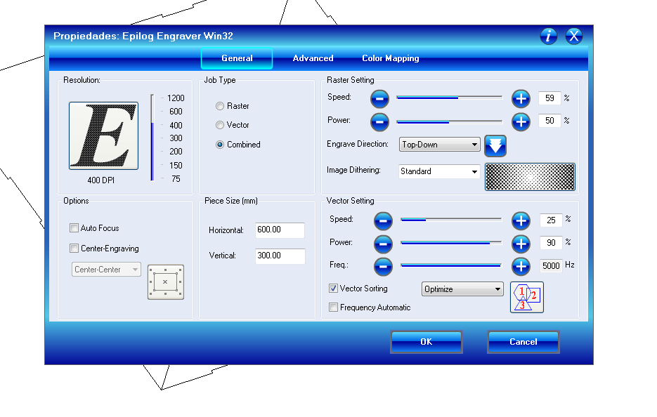
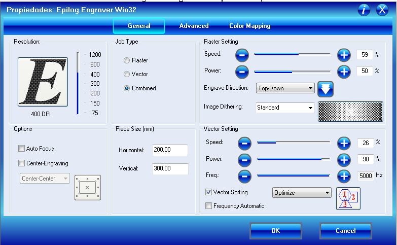
The parameters for the Epilog 40w for cut acrylic of 2mm is 25% of Speed 90% power 5000 Hz frequency
Top and Bottom of the pyramid
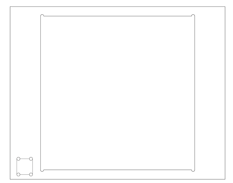
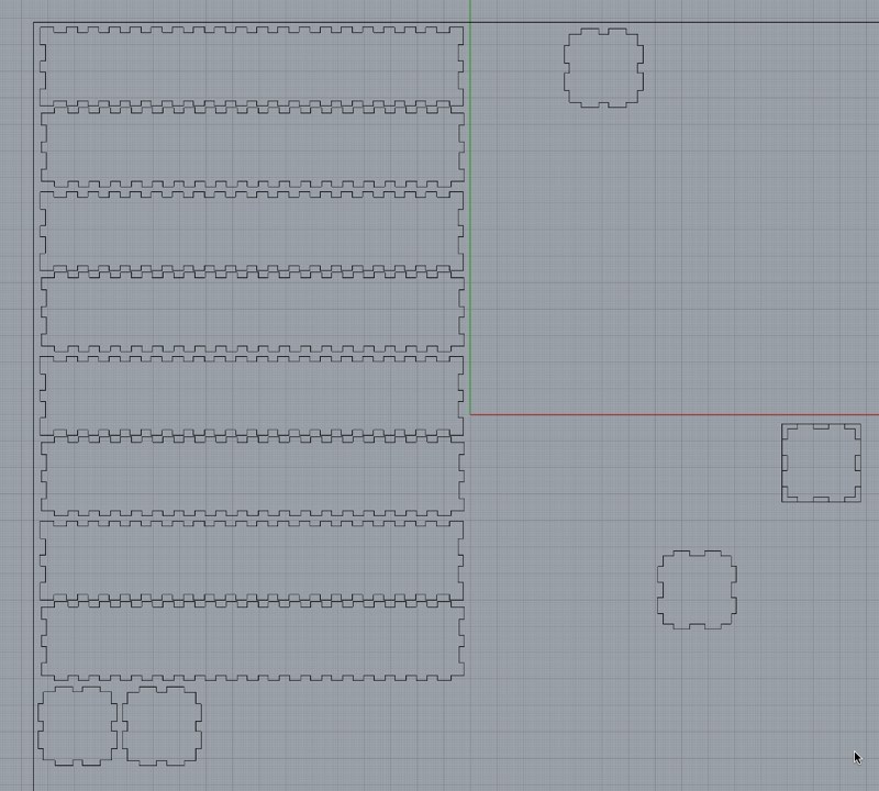
In the following image you can see the top and bottom of the pyramid. Is a very simple structure, the bottom is the one with a square factor hole, where it will fit the pyramid and has 29 cm of side. With the CNC will make just one pass with the milling bit with 4mm deep, that will help to avoid that the pyramid being dismantle as is put together with just 45º press-fit that is not the most stable. So it will help to keep the shape.
The top has a rectangle shaped hole, as the screen of the monitor is 34x27cm
Both sides has 4 holes for columns 3x3 cm and every hole has 6mm circles for easier entrance of the milling bit.
Here you can see the both bottom and upper parts
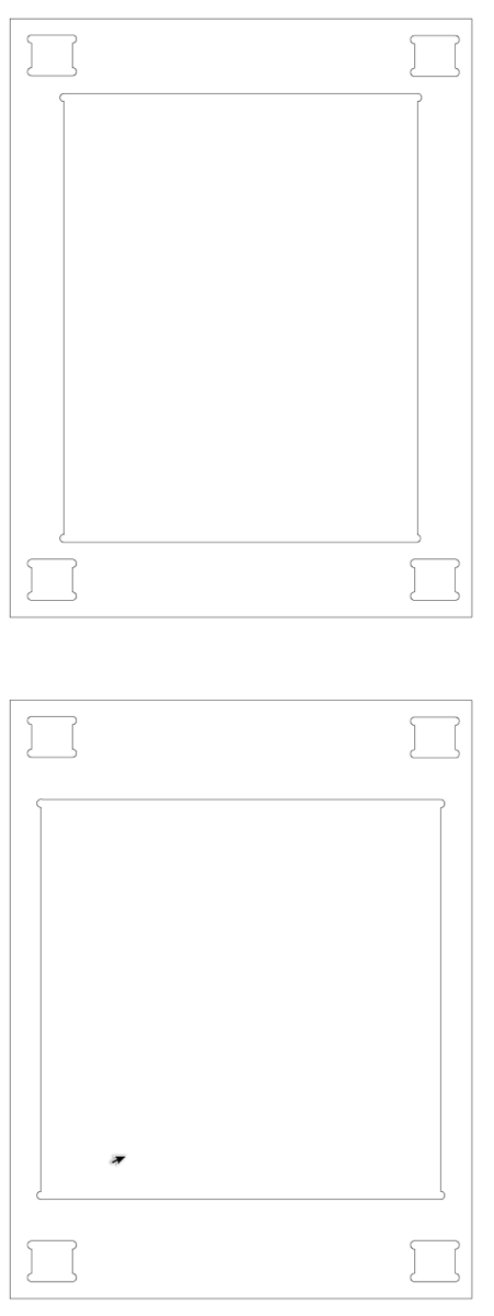
You can download the Adobe Illustrator file of the structure of the pyramid here
You can see the bottom part, that after thinking in Vectric I just use the shape of the square as cut line but only with a depth of 4mm, just one pass, instead of remove material of all the square.
That groove helps to keep in place and shape the pyramid. Also are visible the holes of 6mm to help the bit move in the corners both groove and holes of columns.
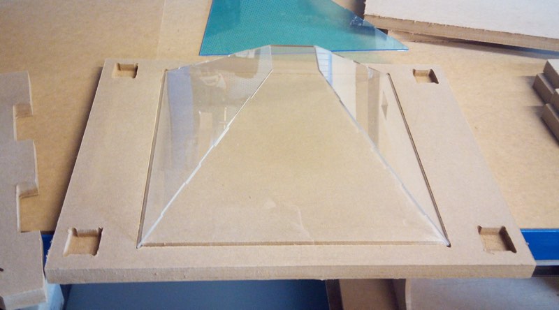
Columns
To support the upper part of the pyramid where the monitor will stand, I need 4 columns, that I choose to made them of acrylic as are a known material, is transparent that is a quality needed to avoid distractions when you turn around the pyramid and is easy cut by the Epilog
The columns have a base of 3mm to don't be so big but still be able to support upper part and 17 cm of height as each hole is 4 mm deep and you need the height of the pyramid plus a little space and add that 4cm in total.
The easiest method for make a box is made a template with makercase, save the svg generate open in Inkscape and save in pdf format for importing in Rhinoceros, for me it was the best workflow for my needs.
You can notice that after some test the base is not 30mm is 29.65mm for best fitting
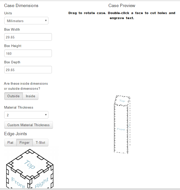
The best practice is to make a little box to test both the fitting of kerf in the acrylic and how it fit in the holes milled by the cnc, and use that box to loose a little and make easier to introduce final pieces.
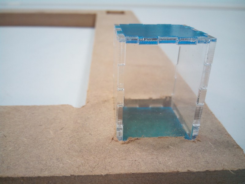
Fablab León use Rhinoceros for laser cutting in the Epilog 40w that has a 600 mm x 300 mm area of cutting. As the sheets are 500 mm x 1000 mm, you get 3 sheets of 500x300 mm that you have to cut with a special acrylic cutter that make that wonderful noise like forks scratching plates ;)
Again as is the same acrylic of 2mm the parameters of Epilog driver are the same 25 S / 90% P / 5000 Hz F.
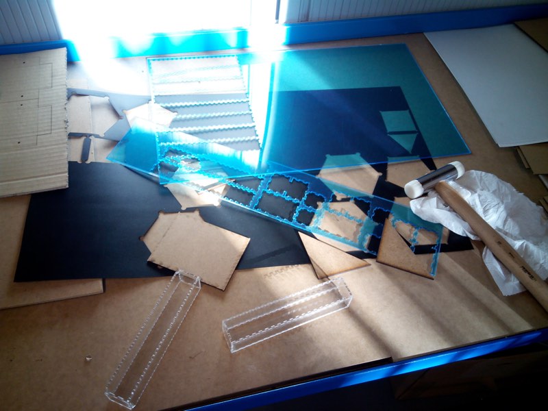
You can use the rubber hammer to help you to fit the joins of the columns.
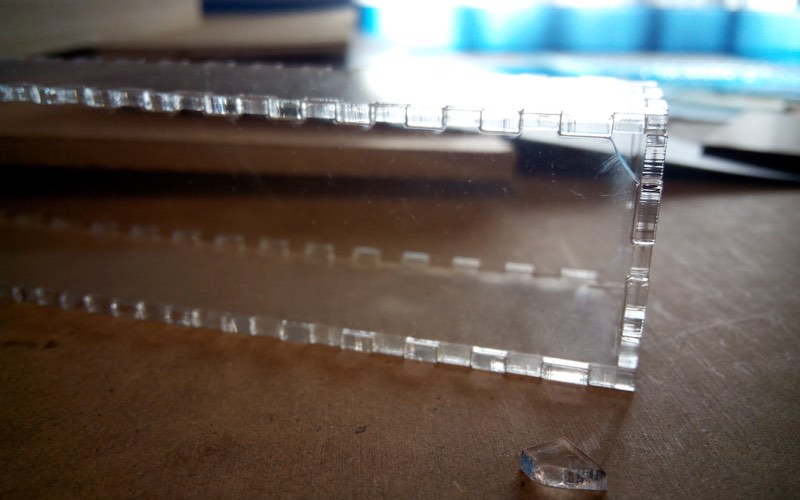
As is normal the push of the forces even you put a layer between the acrylic and the hammer will usually crack the corners. I didn't make any drama as the join is strong and they will be hidden in the holes as again they have 4 mm of depth.
You can see how the pyramid structure is almost built.
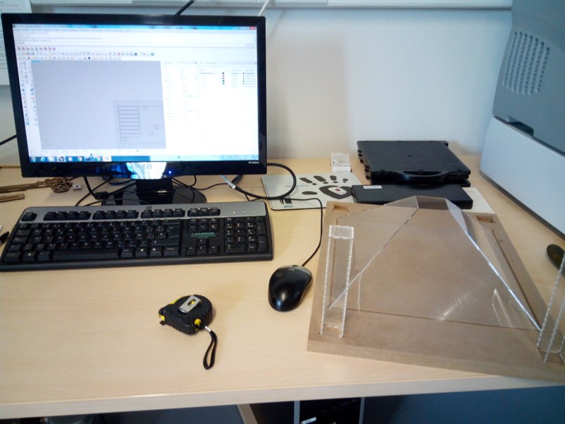
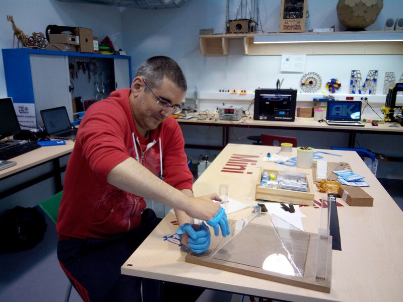
You can see that Leoncio approve the result with this little 3d printed clone inside the pyramid.
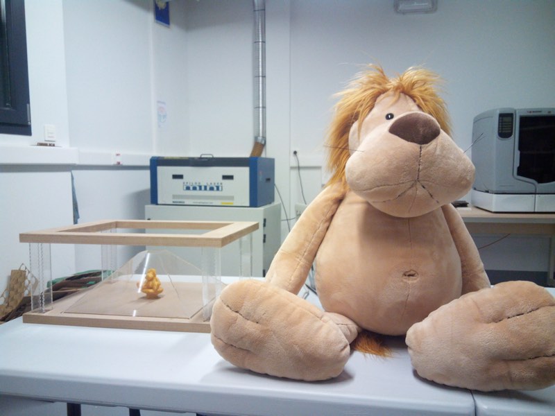
Checking that at least I have something to show to everyone.
Z structure design
Fearing problems of complexity with full pyramid app, and also because the structure was a little more simple, I decide to make also another model will only one view, shaped similar to Z letter.
I based the design in this photo I found in Internet.
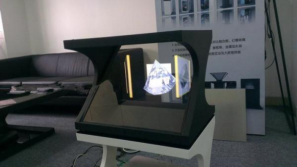
Again started to mess with Adobe Illustrator making sketches for refine them in Rhinoceros
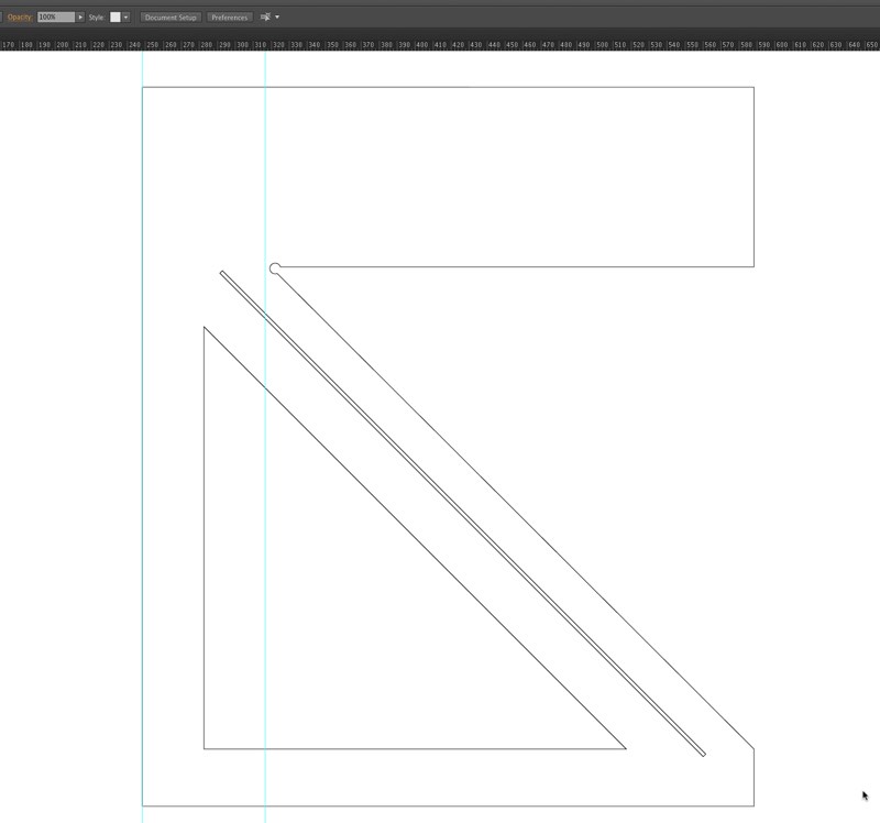
The first sketch has a potential flaw as my wise guru Nuria Robles point me, and that is that first joint at the borders was very thing and will probably break so I have to redesign it again, learning in the process.
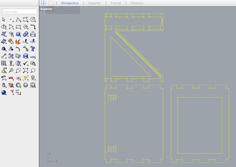
Is not bad idea to make a little model with the laser, to see if has any sense and discover any potential flaw in the design, even if not will perfectly fit together.
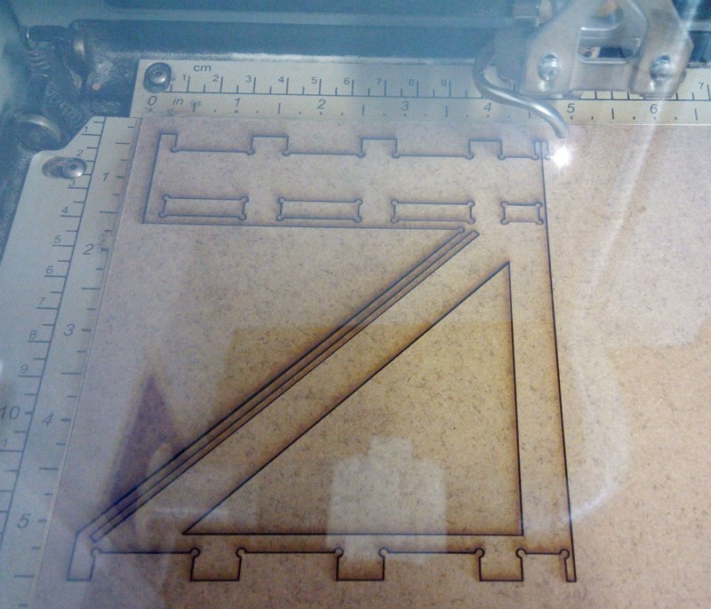
Here you can see a video of the Epilog Mini cutting the mini Z display.
After discovering this flat, I fix and put equidistance joints with would be more stable and stronger
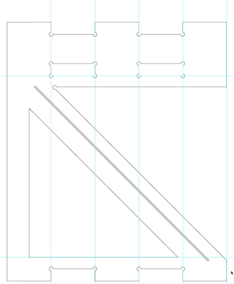
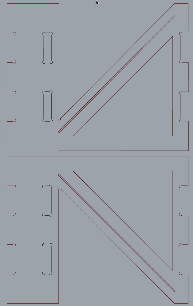
The following SVG that you can save but is not the best version of this design, show us the 3 parts that will get modify in Vectric. One side that you will mirror it for get 2, bottom and upper parts that are flat and same design, and middle part with a hole for the screen.
After milling the parts I discover another problem, I made the dimensions of holes thinking that the thickness of the material was 18.9mm, that is correct but under being vacuumed, so in normal conditions was around 19.5mm so I have less space for monitor screen and my full holes for fitting this middle part was to small.
Also the holes for make easier for the drilling bit make corners were not working as was just 6 millimeters the same dimension of bit, and you have to make a little bigger to force Vectric enter in that path. If some object is smaller or same size the bit won't enter.
Thanx to instructor and old Fabacademy Pablo Nuñez that knows very well the CNC of the Fablab teach me some tricks and help me modifying the file for correct milling apart of cheering me up.
You can download the final version for milling in Rhinoceros here, the upper, bottom and middle horizontal parts you can get from the svg image above or you can download this Adobe Illustrator file
Z structure milling
This section is also valid for the previous pyramid design that is a little more simple in strategies of milling.
You can download Vectric Aspire data here.
For this part I use the CNC of Fablab León, that has a maximum of 2000mm x 1000mm. I move in a smaller scale as parts are not bigger than around 500x400 mm
The usual workflow is design usually in Rhinoceros, export a dxf file to be imported in Vectric and generate the G-codes for copying them in a usb and transfer to the machine remote control unit.
Again Is very important that you follow every security rule as is a dangerous machine, wear safety glasses and ear protection as is a very noisy one
Don't have any loose thing like bracelets, wristwatch, long hair, long sleeves... that can be tangle by the rotation of the mill, even is closed in it's protection
You have to be very careful with dust, trying to clean it with the vacuum to avoid be ignite by the friction of the rotation of the mill, and don't breath it.
As the wooden material I use is not so good it transform easily in dust, and even I wear glasses I was several days with a little eye irritation in the lacrimal that was not harmful but a little bothering.
Also is not bad that you don't be "alone" when using the machine, is safer if someone is in hearing range if you have any problem or you need help.
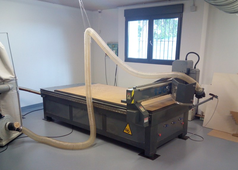
I use mostly the 6 mm drilling bit both for boxing, and for cutting by the inside and the outside. Has the standard fixation diameter. The width of the material is 18,9 suffering vacuum, that is important is not small difference without this compression.
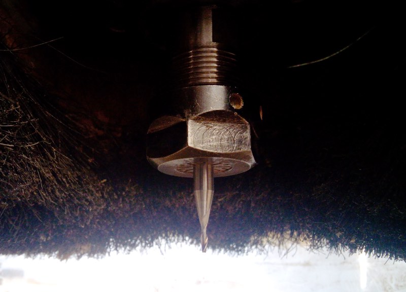
I only have to change, the milling bit for a 2 mm diameter but still standard fixation for make a little groove to stick the sheet of acrylic. If you want that Vectric generate a path for a tool, you have to design a little bigger. So to make a box for 2mm it should be 2.5mm for example.
Again you have to check the speed of advance and rotation of the tools and verify is the correct, so is almost mandatory that talk about this with your instructor to avoid any problems
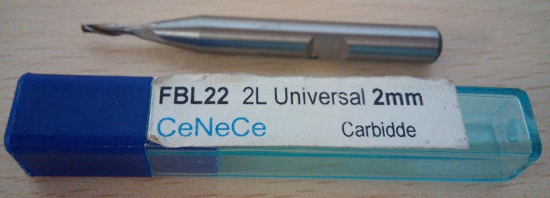
The 2mm lines are the first to be cut, with inner cut strategy but in this case with just 2mm of depth, then I can switch bits and do all the rest with the 6mm drilling bit
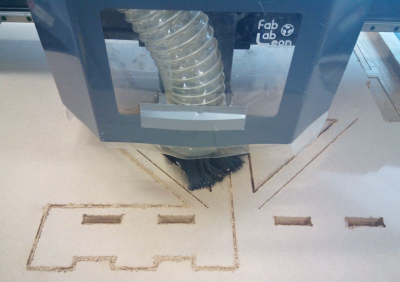
You can see both sides mirroring finished. This ones are the second version, that fix the measure problem of that I took the value of the width of the material being vacuumed of 18,9mm instead a higher value of 19,3mm in normal state so the space of the monitor was smaller and the holes weren't big enough. Still have to apply me measure twice, think four times, and do once.
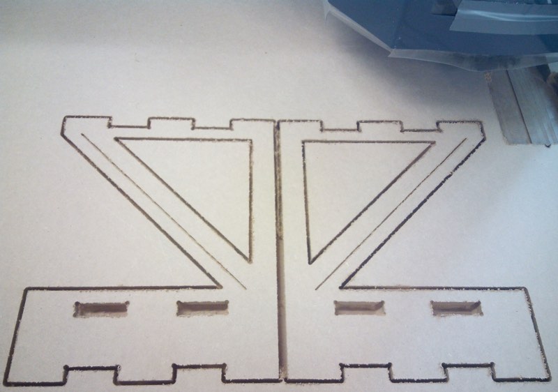
You can see here the bottom and top layers with a previous version of the side.
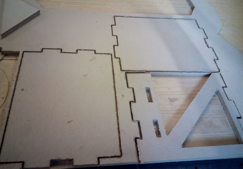
Here I check that everything is fine and I can press-fit the monitor screen layer that was the one that need holes for press-fit. If you look carefully you can even notice that the new version has a little more space from holes to down part that the one cut. Even they are inverted for real position.
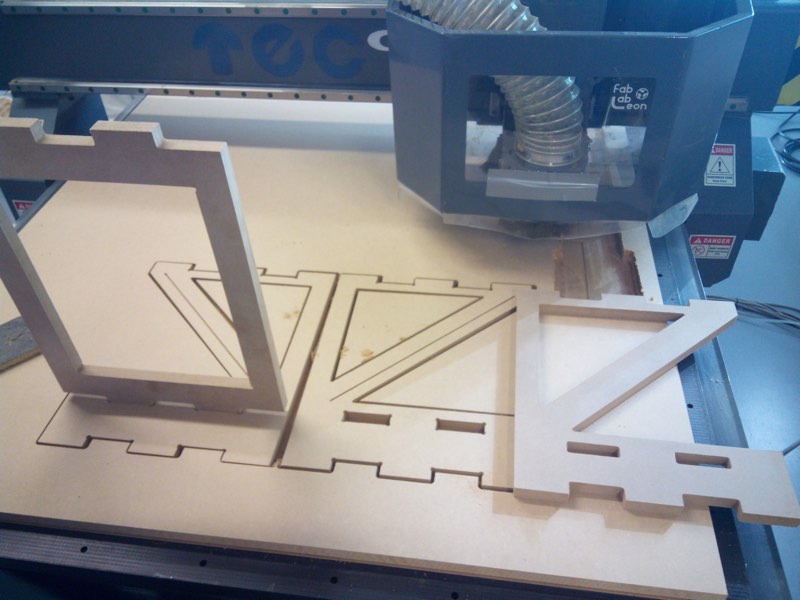
This material needs a good work with sandpaper. A good trick if to do it before you separate parts just after milling and cutting.
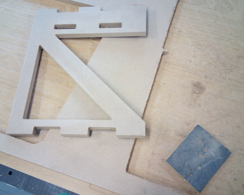
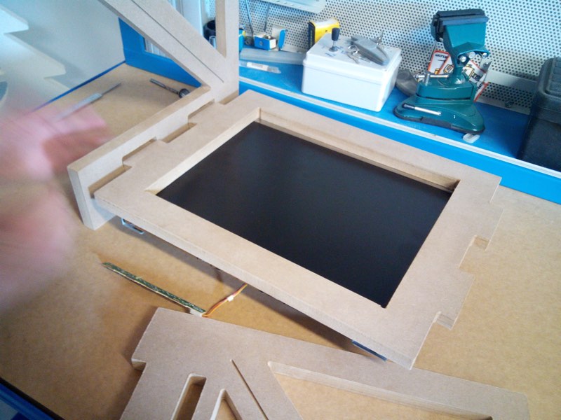
You can see a couple of short videos of the cnc working in Z shape
NFC + Fabkit
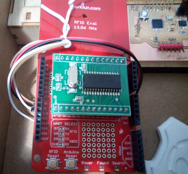
For NFC interaction I use a kit that is an SM130 Mifare reader chip and a shield with a PCB antenna.
You can learn a lot about this SM130 chip and MiFare specifications reading the datasheet.
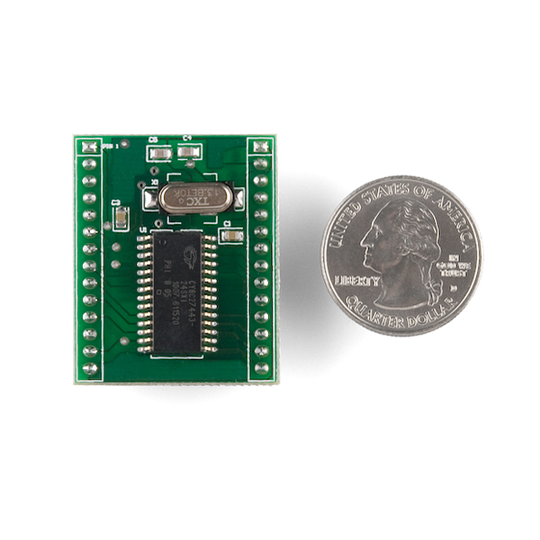
The good thing of this shield is that has a PCBs Antenna, and even you can mill perfectly one (and I will make one), now is above the scope and my skills for this project and will be a To Do thing for future versions.
You can play with the eagle files of Sparkfun, but as it has several capacitors of smaller print I have to adapt and it will take a little more time.
Also is very helpful as has 3 leds, one for power, one for connections and one for reading so perfect for troubleshooting that is one thing you need in this type of projects.
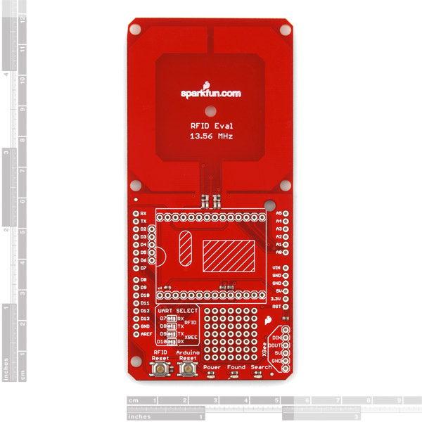
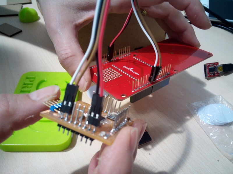
It only needs 4 pins so is easy to connect even with long cables
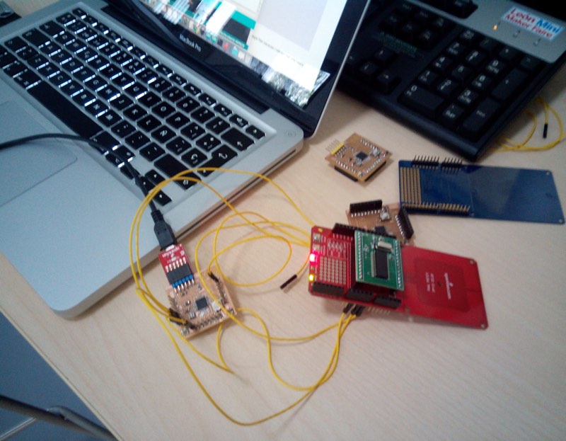
But everything is better with the correct length cables and if they have colors even much better of easy identification of each pin.
Programing the Fabkit with the NFC SM130 Sparkfun Shield
You can download the NFC-Fabkit Arduino file here.
This shield is more easy to program than the Adafruit PN532 as you don't have to download any library and just use 4 pins 2 for TX/RX and VCC and GND.
You have to read previously with the example code provided by Sparkfun the tags to know their unique IDs.
Then adapt that code to just send a serial byte when detect specific tags, I just use the last ID value that is enough for this test.
NFC Tokens
All the Fabacademy course I was searching a way to make nice fabable smart objects and a way to make easy. I had several experiences with tag readers of both RFID 125 KHz and NFC 13.56 MHz.
Even Neil point to some of his previous works like you can read in this fascinating paper. From page 5 start talking about this physical icons and LC circuits.
I also found how to transform our beloved attiny 85 in one RFID tag in this article. But for my time and knowledge at this points it was dance with the devil, as any classmate whom read this know that we don't have many time for crazy experiments that can fail, even everyone loves crazy fab experiments.
Also Neil insist that this is only the first step and that is better you make little parts that works and improve in each cycle of development, or like is the same, don't bite more than you can swallow.
So for this project I don't need that everything is 100% fabable, so I can use "commercial" programmed NFC tags, and stick them to fabricated objects.
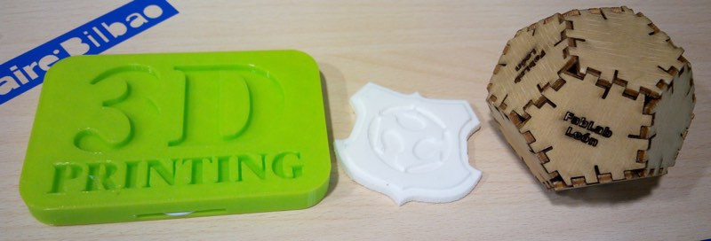
NFC tags
I bought in an aliexpress offer some nfc 13.56 MHz tokens this was the snapshot of the offer.

This are the specifications that the seller has in the page, for me at least get recognized by the reader.
Chip Type: FM1108
Storage capacity: 8Kbit, 16 partitions, each partition two passwords
Operating frequency: 13.56 MHz
Communication speed: 106K Boud
Reading distance: 2.5 ~ 10cm
Reading time: 1 ~ 2ms
Working temperature: -20c ~ 55c
Endurance:> 100,000 times
Data retention:> 10 years
Executive Standard: ISO14443A
Typical applications: enterprise / campus card, bus card, highway fees, parking, residential management
3d printed token
Again my instructor Nuria guide me by the correct way and suggest me a 3d printed brick style object that I could later modify and with a space for this tags.
It's designed using simple extrusion of 2D shape and with boolean operations of substration of the letters and shape for tag you have a nice 3D object in Rhinoceros.
You can download Rhinoceros file here or just the stl for printing here
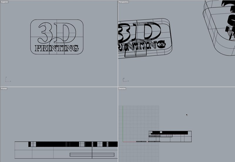
You can easiy see the token 3d model here, also you can download the stl from Sketchfab web.
You can see a video of the Makerbot printing this smartobject.
Casting and Molding (Composite) Token
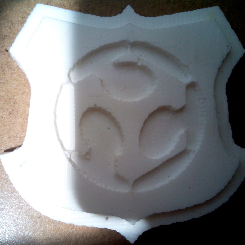
This token is the product of week 12 - Molding and Casting practice that is a little Fab Shield that I try to recreate of the week 7- CNC - Make something Big.
First you make the mold with the Modela-20MX in a wax brick.
Using the silicone product is best for your goal in this case was Oomoo, as negative mold.
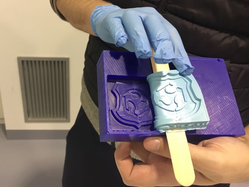
Then you can the copies you need in other products.
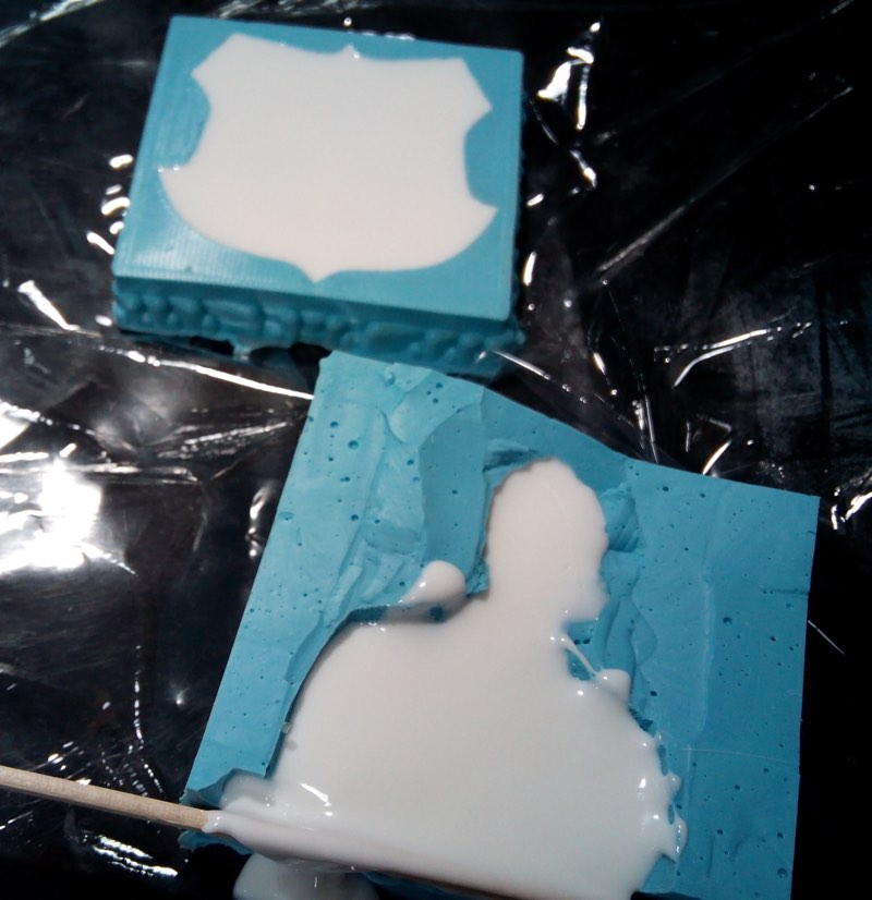
And you have your wonderful fabshield token.
Lasercut Token
The laser cut token is just one of the examples that FabLab León have to show people the great possibilities of LaserCutting and is similar of other press-fits models done during the FabAcademy.
One great thing of NFC tags is that you can stick them in almost anyplace.
DMXduino
This is a wonderful example that you can learn during the Fabacademy and beat previous challenges of some weeks. This is fix the problems I have during ECAD for designing some boards, just mostly by ratnest impossible to fix for me.
I modify the FabKit v0.3 as are the ones that both schematic and board view are linked without problem, remove some pins headers and start adding the SN75176 chip. You can use MAX485, MAX487, ST485, SN7517 components.
Are 8 pin in pinhole or SMD shape factors
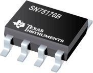
The data-sheet for the SN75176 is available in pdf here.
The classic diagram for connecting this integrated circuit to AtMega is this:
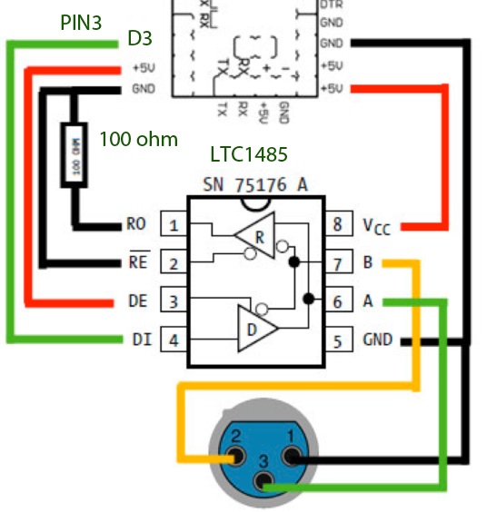
You can see that is not very difficult, using just 1 pin for signal of the Arduino, GND and VCC connections and a XLR connector of 3 pins for interfacing with lights fixtures.
Eagle Ecad Design
Using the FabKit v 0.3 schematic I add the SN7517, you can use the Maxim library in Eagle to add a Max485 smd IC as has the same pinout and trace.
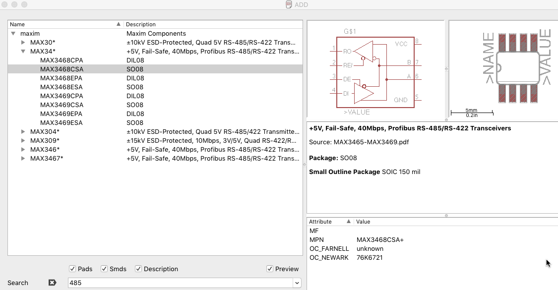
The schematic connections would be like this:
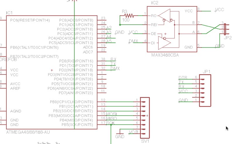
After finishing the paths I notice that I have a free empty space and that I have a full header of pins mostly Analogs ones.
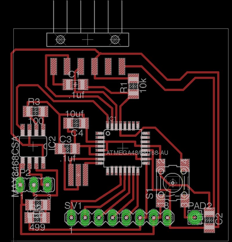
So I also made a header for that A2-A5 pins.
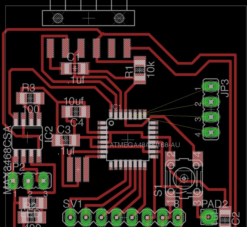
I'm getting a little better in making routes.
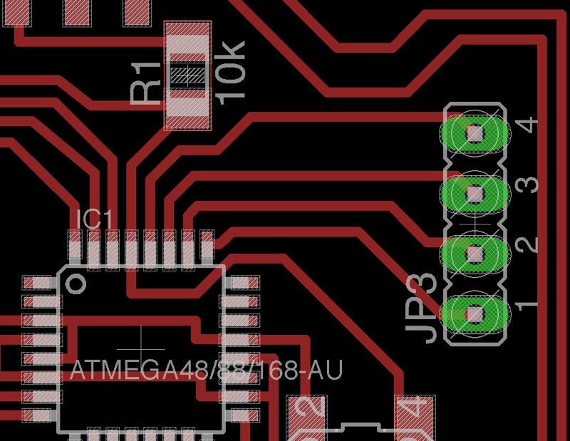
You can download the Eagle Files (Board and Schematic) here.
Images for milling
Here you can download the different images for milling in the Modela the dmxduino
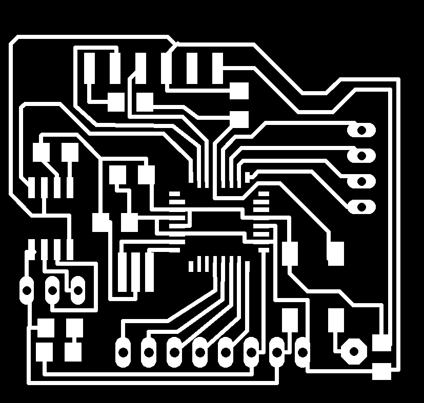
The 64' Traces. Be Aware that path of pin 6 is very near of pin 5 pad and you probably have to remove some material of pad to avoid short circuit.
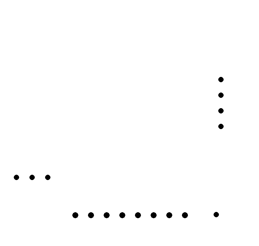
Holes with cut 32' drilling bit.
Cutting Mask that is the same as a normal Fab Kit v0.2.

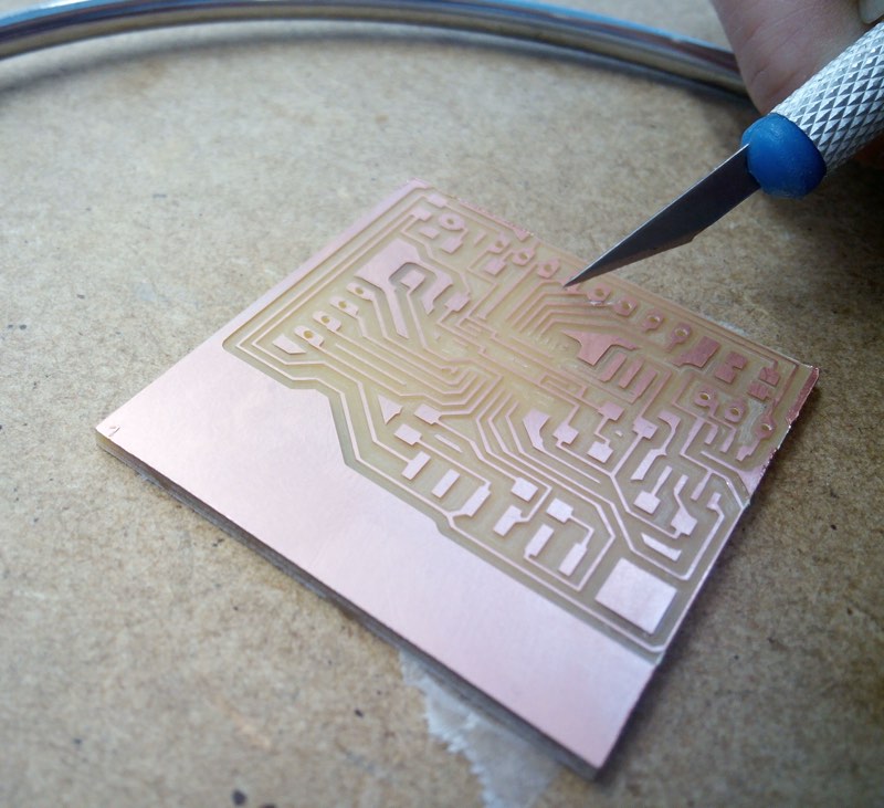
After milling maybe you can need to just remove some cooper of some little traces in the SN75176 pin 5 pad that is sticky to another path, nothing to worry.
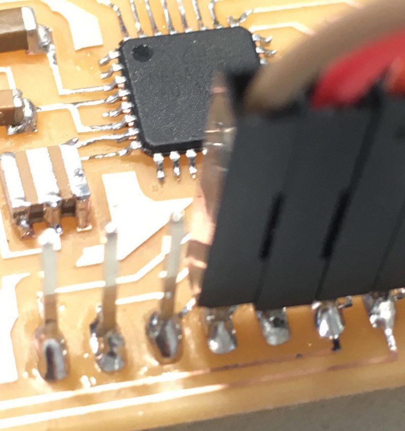
Using long pin headers make a little more difficult to solder and make and stable connecting. I have a little problem with a pin with less tin that didn't let me establish connection with avrdude and fabkit Dmx so I have to a better soldering.
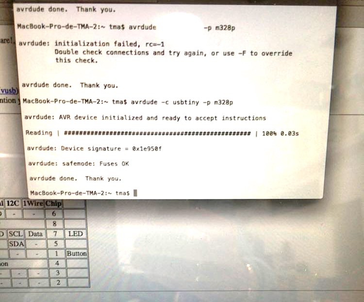
Then I could say hello to the microcontroller and burn the bootloader.
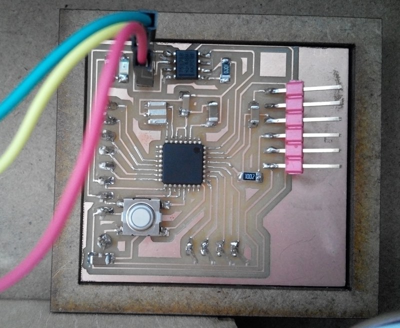
After soldering you have this Fabkit with DMX, also has the modification of an Atmega 328p with 16MHz resonator like an Arduino UNO for programming.
Programming the Fabkit DMX
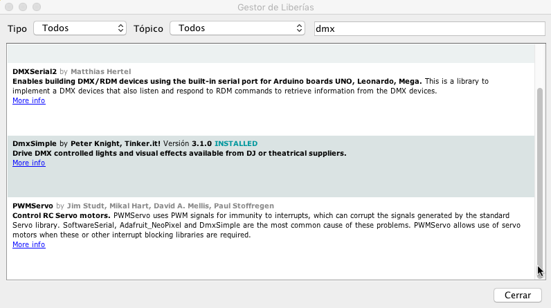
The Fabkit DMX is like an Arduino UNO, so you just need to download the DMXsimple library to Arduino IDE and start programming. The DMX signal pin is the Digital 2.
You can download the Arduino ino file of DMX activate with Serial here.
Is a very easy file, Read the serial and if is one byte known send data to a dmx fixture, in this case a chinese one, where 1 channel is light intensity so is always 255, (128 or other values for low or fast blinking), and 2-Red, 3-Blue, 4-Green.
Of course you have to adapt the program to the fixtures you have and how many channels you need, I would be able to manage at least 50-70 channels without problem.
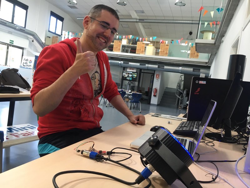
Victory sign because It worked at first try, and I didn't believe my luck to don't have any problem and one important goal was achieved.
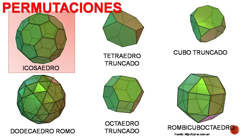
Truncated octahedron
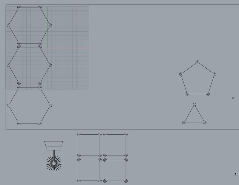
Trying to make the most complete project I thought in make another polygon for using as mapping and led lights as slave unit of the altar reader unit so I designed another type of pressfit group of shapes for making polygons in a plastic style material that can be cut in the laser.
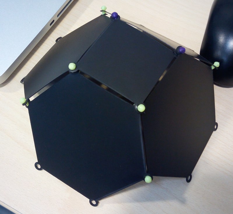
The parts can be joined with a 3d printed pinhole of 3.6 mm of diameter.
The Parameters for Epilog driver cutting are Speed : 35% - Power : 50% and Frequency : 5000 Hz for a new tube.
You can download the Adobe Illustrator Truncated octahedron parts here
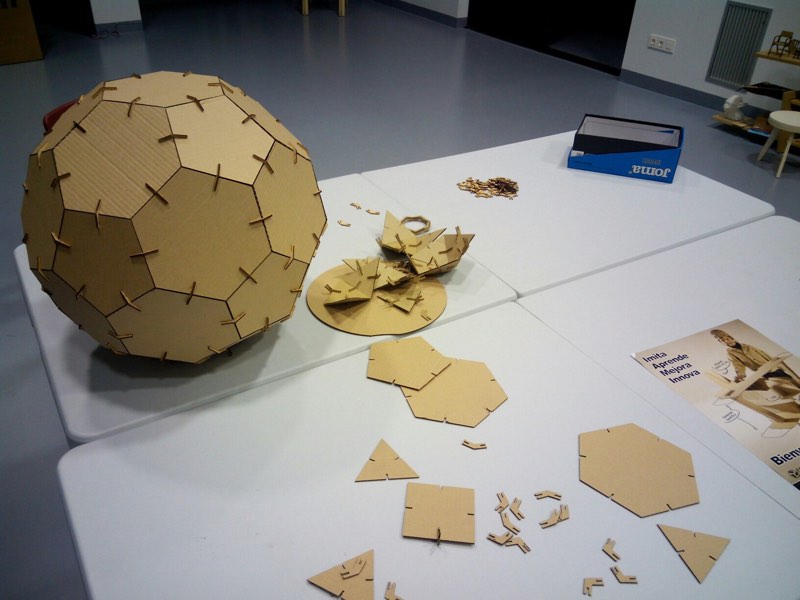
Truncated icosahedron
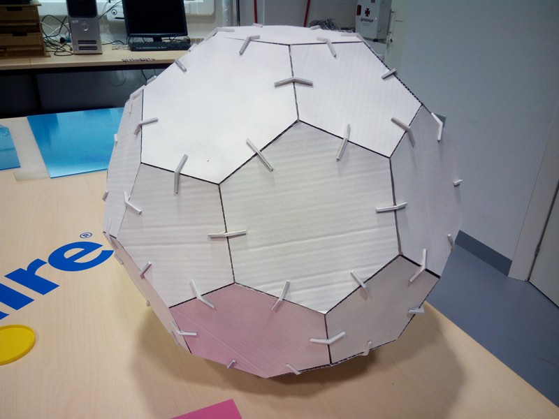
In week 3 I made and assignment about computer controlled cutting I made several simple forms like hexagons, pentagons, triangles that finally get into the shape of a truncated icosahedron.
I decided to use it as video-mapping surface to demonstrate that is easy to make this surfaces in a Fab Lab and make nice results.
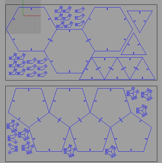
You can download the Rhinoceros v4.0 Truncated icosahedron parts here
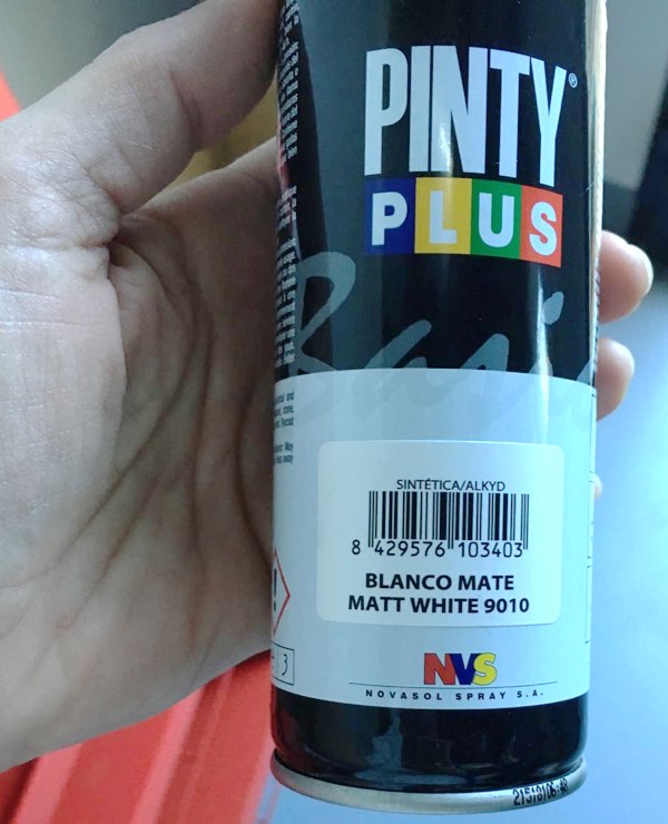
I bought several spray paint cans in matte white for painting the icosahedron
As we have very nice hot days, was very easy to paint as time between layers was short as it dried very fast.
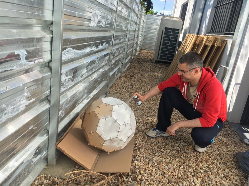
Here is the finished painted icosahedron, not perfect but fine for projection.
Box for electronics
Neil during the project presentation insist a lot about packaging of electronics, to don't have a mess with boards hanging around and cables to be seen everywhere.
My guru Nuria Robles that is a very perfectionist person, guide me about to find a solution for my project, that even in first draws of the project this box should be a nice example of laser cutting or carving has transform in a practical simple box.
Again the template is done with maker case for mdf wood and acrylic of 3 mm.
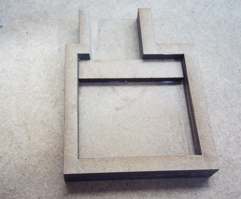
For enveloping the fab kits and set them in a fixed position she show me a trick of making boxes adding layers of material and the result is pretty nice.
The space layered for a standard Fab Kit
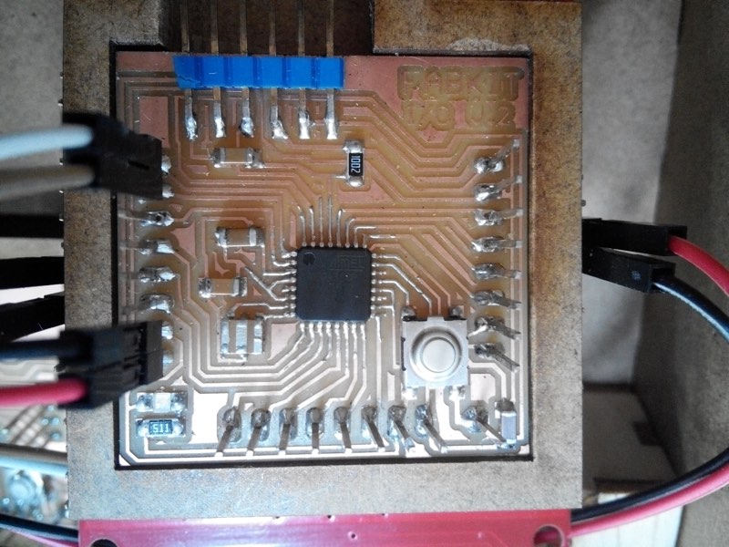
The fab kit called Blue Grumpy Smurf in its nest.
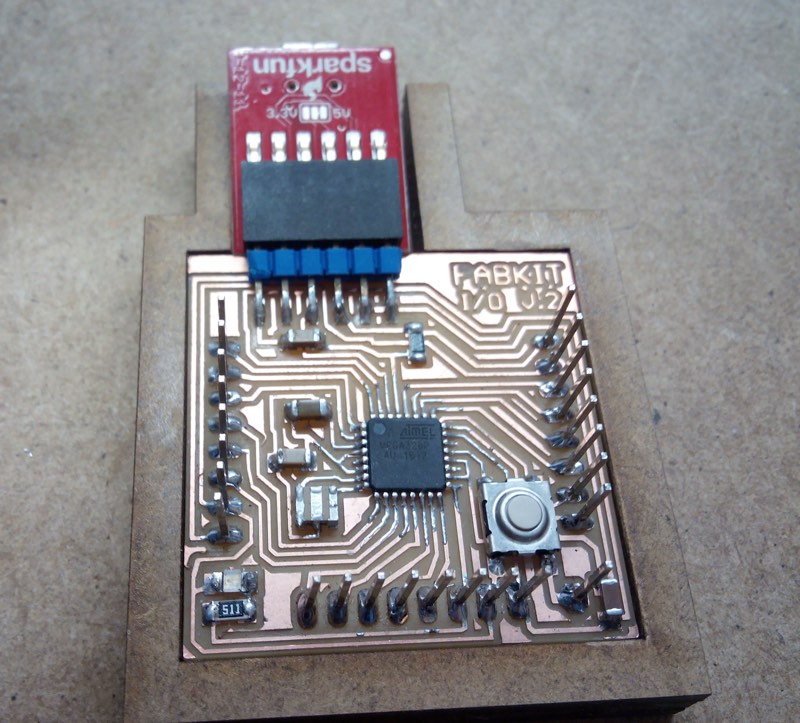
The dmxduino also in its comfortable bed, with the streetlight cables.

I add a little box that I found around for balance the antenna of the pcb shield and with the holes for dmx and usb, everything has a place, and each thing in its place. More clean and nice to see it.
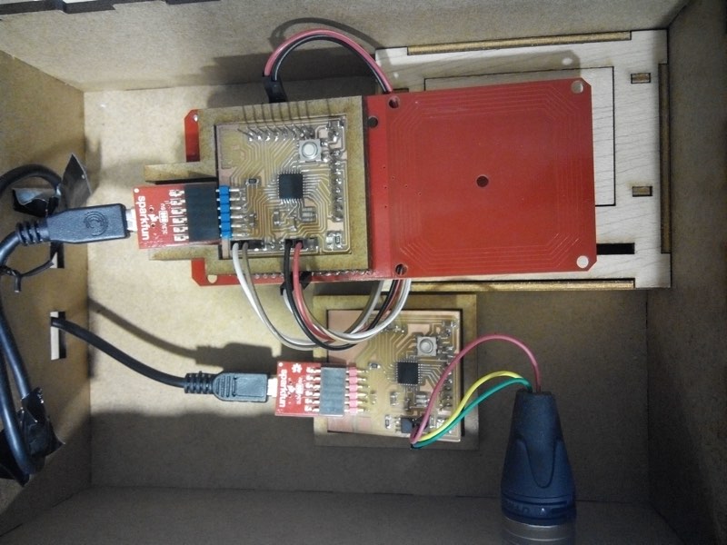
I also tie the cables with a classic bread tie,
Here you can see the Rhinoceros file with the different parts and distribution boxes of the altar. As Nuria also suggest me, the acrylic is engrave from inside, so the correct one is the mirrored.
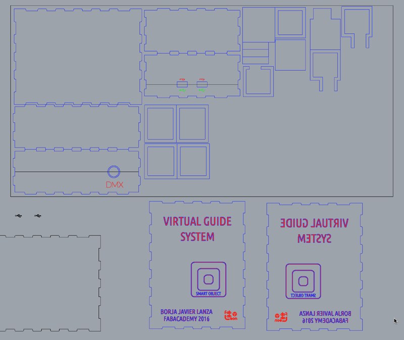
You can download the Rhinoceros 4.0 file of the structure of box of electronics and little parts for fix the Fab Kits inside here
Acrylic upper cover
I have a little sheet of acrylic from previous test for the pyramid, with time it was scratched so I give it a try to be used for this, but the type of acrylic is bad and get smoked, blurred dirty, near the places the laser cut the part
Unity App
Code for Reviewing
Here you can download the unity C# scripts
The project you can download it here. It's 5.4 version at June 2016.
Unity is a Game Engine that has a free user version for learning that has lot of possibilities in the interaction field, as it has support of Serial and OSC, even I didn't have the success I wanted for this little project.
You can export your code to many platforms, like Mac, Windows, WebGL and paying in Android or iOSC mobiles OS.
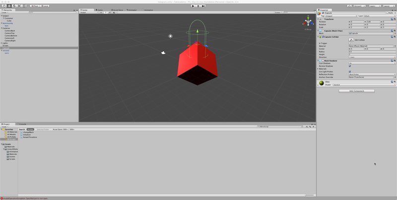
I use a template that I found in Internet done by Nikos Chagialas and that it has the structure of the 4 cameras done with a little rotation and that you can download here and a backup inside this repository here.
You can import the asset and it will include an scene that you can change and adapt to your needs. But you have 4 cameras in the correct place when you play, showing an object rotating.
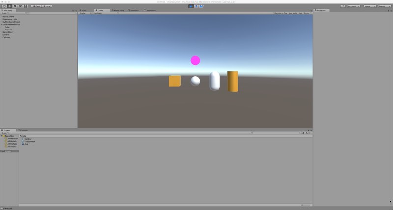
Then I proceed to change the scene adding other GameObjects to the scene for example the 3dObjects or forms like a cube, a sphere or a capsule. Also my Leoncio 3d Scanned model was invited to the party.
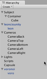
Here is the final hierarchy of the scene.
I create an empty GameObject that I named scripts and I use it as placeholder of any global script that have to run during play and affect all the objects, adding then a script component in this case a ChangeMesh class.
Here is the C# script that run and change the mesh and texture of the GameObject that rotate and is in the center of the pyramid display.
Any global variable that we declare in an Unity script will appear as elements to configure in the own component inside the interface.
As I declare these ones:
			   public GameObject MyMainGameObject;

public GameObject[] arrayGM = new GameObject[4];
I have a Main Game Object that I select the cube object that is the one that also has the rotation script as the one that will be used for interchange the meshes of the other objects, like the capsule or the lion
The other object is an Array of 4 Game objects that are the ones I'm going to interchange. Of course you can change this as your needs, that are the wonders of programming.
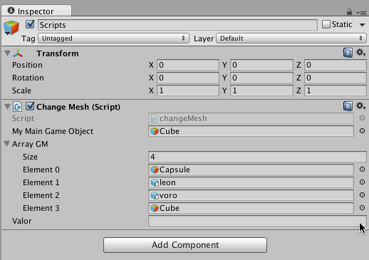
As many languages like for example Openframeworks it has a Update() loop that is going to run endless until app quits and its used for declare processes that need to get update in each cycle, in this case is a call for function UpdateMesh() that depending the actions of the user, in this case pressing keys in the keyboard, pity that is not serial read messages as I got problems.
The conditional if just read the key pressed and if has an event associated make a change of the MainGameObject mesh to one of the ArrayGM[]
if (Input.GetKeyDown (KeyCode.A)) {

			MyMainGameObject.GetComponent|< MeshFilter> ().mesh = arrayGM[0].GetComponent"<MeshFilter>().sharedMesh;

			MyMainGameObject.GetComponent<MeshRenderer> ().material = arrayGM[0].GetComponent<MeshRenderer> ().sharedMaterial;

			Debug.Log ("A Pressed");

sp.WriteLine("a");

}
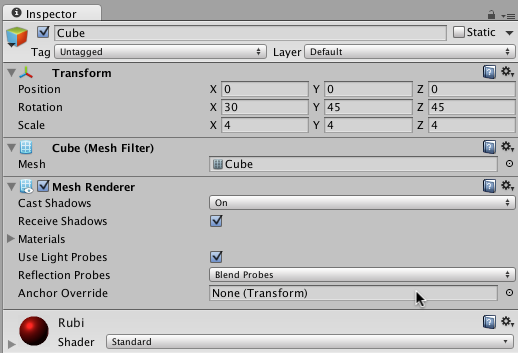
The interesting is the Meshfilter().mesh and MeshRenderer.material properties that change the mesh and texture of the MyMainGameObject by the ones in the array, that 2 ones allow you to switch objects without having to creating and destroying copies and also they act like the original cube with its scripts and other properties.
Also we send serial data with sp.WriteLine("a"); that for example Dmxduino code would read it and change the color in this case a red.
In Unity a object has to have a meshRenderer component to be visible in the scene, that is why only Cube have it, and others are invisible, waiting to switch their meshes and textures with it.
You can watch the result of everything in this video
Serial in Unity3D
Create a Serial object in Unity is as easy as we saw in week 16 you only have to declare as like other languages the address of the port and the baud rate. After including the IO library.
using System.IO.Ports;
SerialPort sp = new SerialPort("/dev/tty.usbserial-A603Q1SY", 9600);
Again we have to be sure that our project has full Api Net 2.0 compatibility.
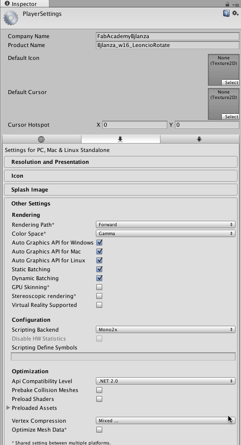
But reading is another different story, even is a very easy to declare I have lot of problems to get stable data income
Openframeworks App
For easy reviewing you have only the code here. The project is below to download, but the important is this code as is the one you want to reuse for your own projects. And just if you want to take a look.
After the problems with the Unity that I can't make for the presentation time an app that correctly respond when get Serial or OSC data, I choose to program a new app in Openframeworks that is also multiplatform and is interesting as also run in Raspberry Pi so the system would me smaller as we don't need a big computer and even we can get even the sensor be read by the RBPi.
I made some test, but as is don't very fabable style I just let it for future improvement ahead the Fab Academy.
So I use Xcode in Mac for program in C++ with Openframeworks tools this App designed for just 1 point of view. You can do with cameras the same 4 pyramid style, but again was a little more complex for the time I have, and will be a goal for next improvements. Everything is free and you have a great community to learn and ask. About Creative Coding.
You can learn and download Openframeworks here, the current version at June of 2016 is 0.93.
You can see a short video of the skeleton of the system and application, that in this alpha version just change a little image but it was the important that the Fab kit Blue I adapt and fabricated worked with the SM130 NFC/RIFD Shield and it communicates with the app.
Serial
Declare and init a serial object after declaring their names in ofApp.h
ofSerial device, dmxduino;
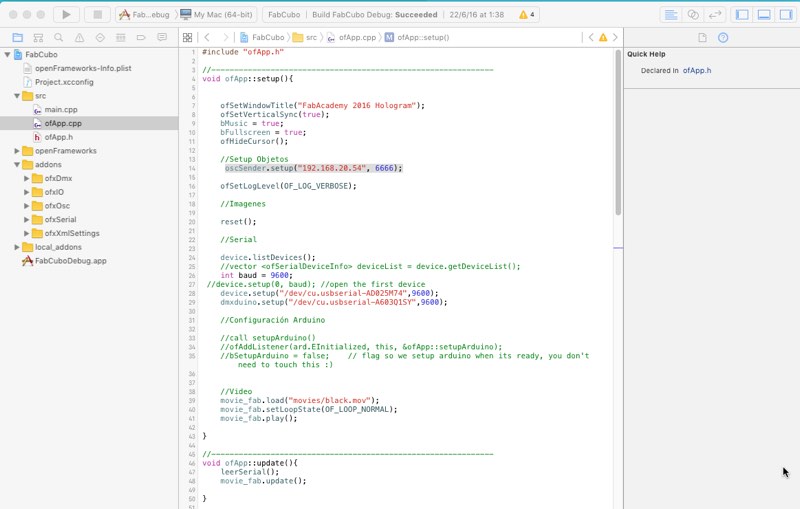
Is as easy as in ofApp.cpp write their port name (in this case Mac ones as FTDI adaptors), and the baud rate as variable or number. You can also said a number in the array return by .getDeviceList();
			//vector  deviceList = device.getDeviceList();

    int baud = 9600;

 //device.setup(0, baud); //open the first device

    device.setup("/dev/cu.usbserial-AD025M74",9600);

    dmxduino.setup("/dev/cu.usbserial-A603Q1SY",9600);
For reading serial data we have seen that this code works fine. I split in a separate function to be called in Update function.
After reading we need to compare the values and then do our actions, with a simple else if loop, that send the OSC messages that I will explain now, also write a byte to dxmduino serial that it will receive and change the lights.
Open Sound Control (OSC)
In ofApp.h we have declare 2 OSC related objects one Receiver and one Sender
    ofxOscReceiver oscReceiver;

    ofxOscSender oscSender;
In the setup() function we just declared the Sender as I only send commands and don't receive none. In this case the ip was of another machine that was running the VTP app.
oscSender.setup("192.168.20.54", 6666);
The ip of the receiver would be the ip of the machine running this app, with a different port maybe just 127.0.0.1, 6667, o the local ip for example 192.168.20.54. This will be reverse for example in the VideoProyectionTools RX-TX TX-RX pins remember? ;)
In compare serial function we call another function named CambiarMatrizOSC (Change OSC Matrix), yes is a good practice split your code in functions and call them in this nest things remember Update() -> LeerSerial() -> CompararSerial() ->CambiarMatrizOSC()
Depending of the data got by LeerSerial() will be compare and execute the CambiaMatrixOSC with different arguments, as you see in the previous code
cambiarMatrizOSC("chess.jpg", "prisme.mov","mkb2.png");
It sends name of the files that are going to show in the VTP layers, each file will go written and sent in a msg for a layer, you will need to modify the function if your need more layers as this is a proof of concept and show classmates the possibilities
You can see here a video of the Application running in the night before the presentation, you can see that is a little hard to record with the phone and try to guess to put correct the token, for example the big green 3d printed brick you only need to put the bottom border that you can see the white nfc disc above the center of the antenna, is easy but you know where is sticked, for that is the visual guide help engraved in the acrylic cover.
And I miss you as the desert miss the rain... wonderful song for hard programming nights
Inverting the images
One problem that I have to solve is that in the way I put the monitor the video appears mirrored vertical, so up was down. To solve this I have to put the video inverted.
This is done with manipulating the Matrix, first you get it, make the transforms you need and later you push it again.
		//Draw the image inverted

    ofPushMatrix(); // We get the Matrix to edit and transform the objects

    ofSetRectMode( OF_RECTMODE_CORNER );

    ofTranslate(0, 720, 0 ); //I translate the axis y of what I going to draw as is 1024x720 video to just down the border

    ofScale( 1, -1, 1 );// Invert the Y axis so it started to draw the image from the bottom to up.

    movie_fab.draw( 0, 0); //I draw the video object in that 0.0. that is instead the left upper corner, is the right bottom corner.

    ofSetRectMode( OF_RECTMODE_CORNER );

    ofPopMatrix();//I return the matrix after all this transforms, to avoid modify any other objects. Even in this case I would need to change everything,
Project and libraries.
You can download here the OpenFrameworks Project.It has been testes with OF 0.93 and you need the following dependencies of libraries.
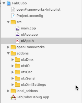
Even I just declare OfxOsc and ofxSerial:
			  #include "ofMain.h"

#include "ofMain.h"

#include "ofxOsc.h"

#include "ofxSerial.h"
You may need understand all the libraries declared as I declare more to have them when I need it in next versions of the app.
ofxSerial, ofxIO as is needed by ofxSerial, ofxXMLSettings and ofxOSC are libraries from the core of OF.
Also if you have an Enttec Open DMX the project has ofxDmx included.
Video Content
I use Apple Motion to produce little short video animations to show them in the Holographic Display
From a very simple start
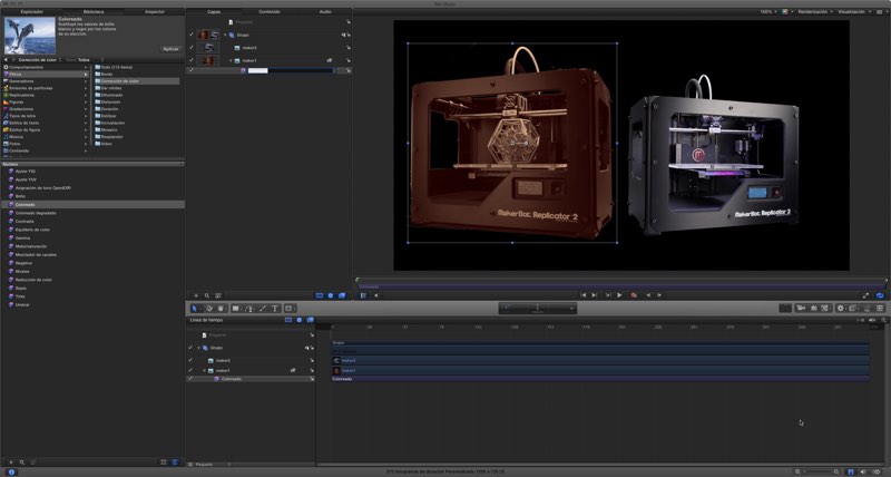
To a complexity of layers and effects
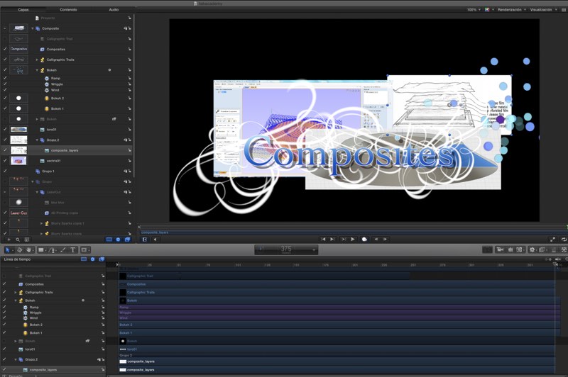
3d Printing
Laser Cut with the epilog 40w.
Composites that should be Molding and Casting as I use the Fab Shield cast but It's fine.
Video Projections Tools 7
You can download Video Projections Tools version 7 here, it's a free app made with MaxMSP with both Windows and Mac version, that make video mapping easy and accepts OSC messages.
The program has different tutorials and a manual, to understand better how to use it. But you create layers for adjusting in size and place and assign different video sources to each layer, that can be shared or not.
In the screenshot you can see that we have that name we pass in OSC in OF app, with CambiarMatrizOSC(), so you just need to import your videos or images, named it properly and take that names to the function, know which layer you want to put your images.
You can create mask with the shape of the faces of your own mapping surfaces for better mapping in that surfaces, for example hexagons and pentagons for icosahedron.
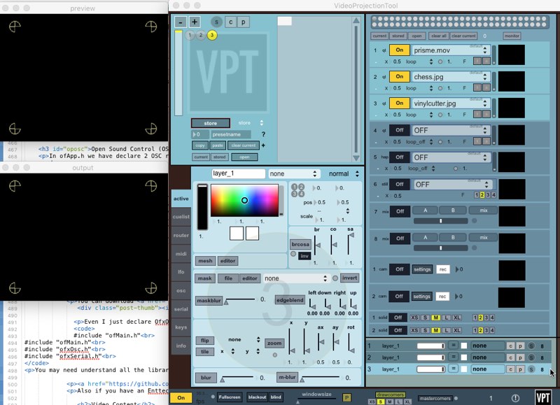
The one important step is how you configure OSC, you see that it can send msgs, but we didn't declare the receiver in the OF function, but as was explained you can easily do it.
The usually port of VTP is 6666, and the ip is 127.0.0.1 if you are running both app in the same machine, or the ip of the other machine is the are different. You can see if a msg has arrive if you have monitor in checked.
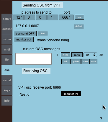
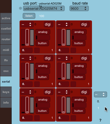
One important and interesting feature is that also accept serial data so we can just adapt our sketches of our microcontroller to control the app without a intermediate app.
