Networking
This week still have that bottlenecks with the Ecad programs and how to solve the problems with the routes that mix and cuts that appear in the design phase, between them. That make me very hard to finally mill any board for testing. With more connections more complexity but sometimes I just can't make more simply so I'm struck. And I have to resolve this fast and smooth for a good workflow. As I tried to design my own NRF2401L boards, that needs 8 Pins plus any other connections you need so finally I go by a easy approach and do I2C with my own Fabkits.
Lesson
Academany Fab-2016.05.11D Lesson 15: Networking and Communications from Fab Academy on Vimeo.
Review
Academany Fab-2016.05.18B Review 15: Networking and Communications from Fab Academy on Vimeo.
I2C with own fabricated Boards
I²C uses only two bidirectional open-drain lines, Serial Data Line (SDA) and Serial Clock Line (SCL), pulled up with resistors. Typical voltages used are +5 V or +3.3 V although systems with other voltages are permitted.
It's very interesting to learn how I2C works and you have several tutorials like Sparkfun, ByteParadigm or Corelis
So for getting a communication we need SDA and SCL with a common Ground for having a reference so we use 3 cables between the boards. As each will have FTDI as power source, and a way of reading serial and transmit data to the user.
In the ATmega168 and 328p microcontrollers this two pins are 27 -A4 (SDA) and 28 - A5 (SCL).
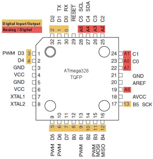
In the Fab Kits are usually in the left pin row if you put FTDI connector looking up.
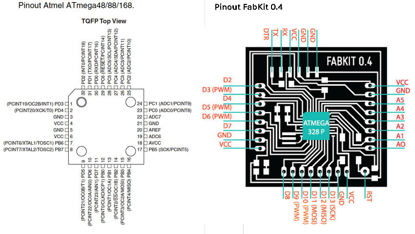
So we have the 3 pins we need all packet together in the left side.
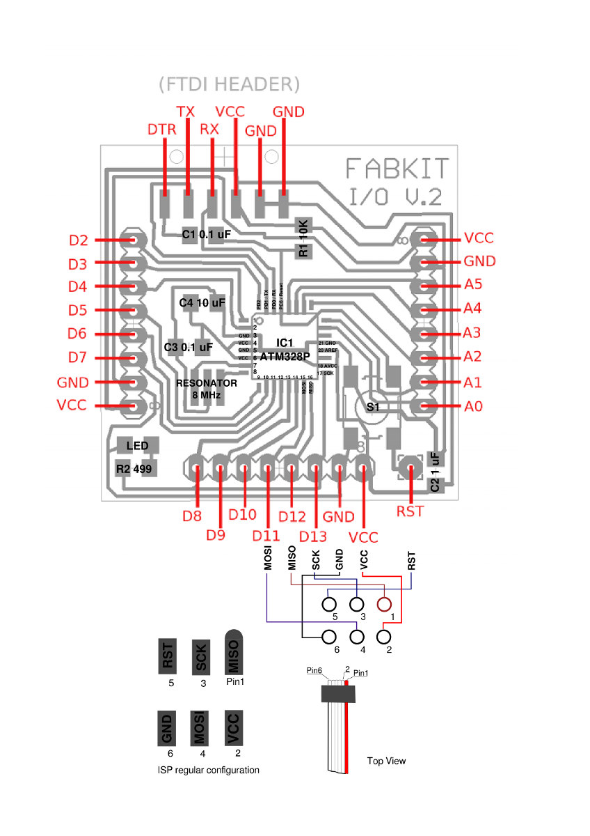
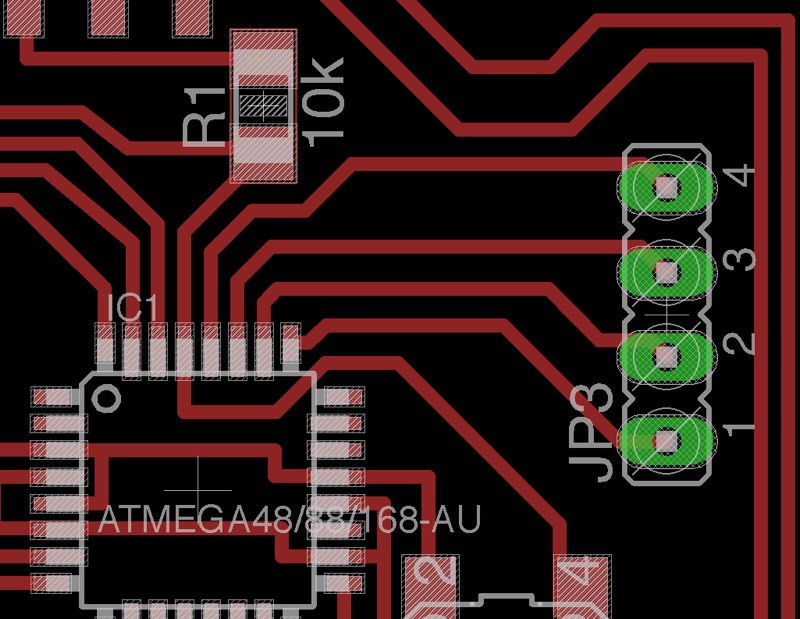
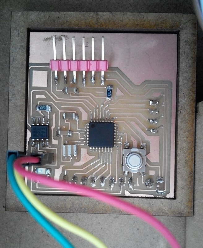
Even nice coincidence is than in the design of the FabDmxduino I recover just that A5-A2 pins, not the Ground but I have the access of SDA and SCL.
Arduino Wire Library
For I2C easy communication that is used in many devices like led matrix or LCD displays, you use the Wire library, that is included in the standard IDE.
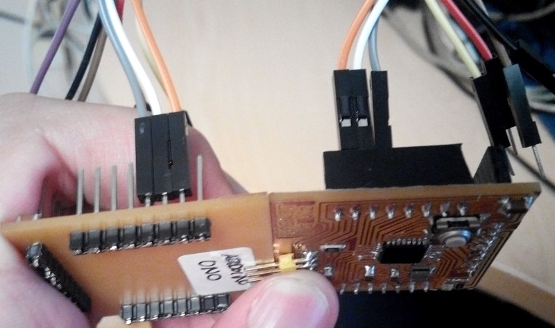
We just need to connect that 3 cables GND, SCL(A5) and SDA(A4) each one to their counterparts in the other board or boards.
In this case the Orange is GND, White is SCL, and Grey SD.
You see the differences of pins styles as Yellow 168 was the first Fabkit I fabricated as test and has female pins in the bottom part and is a like an Arduino Mini 168, while blue is the latest standard Fabkit that I made and is like an Arduino Uno and is prepared for accept shields as it has long pins for the female bottom pins of the shields.
The library Wire, it's begin method allow to specify the direction of the node and if you put nothing will become the master.

Wire.begin()
Wire.begin(address)
Description
Initiate the Wire library and join the I2C bus as a master or slave. This should normally be called only once.
Parameters
address: the 7-bit slave address (optional); if not specified, join the bus as a master.
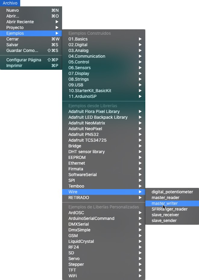
The wire master sender script is the original that you can found as example in the wire library of Arduino.
Of course this menu will change depending the libraries you have installed in your system.
I modified the original example of slave receiver wire script and include just and if conditional to turn on the LED of the Fabkit when it receive a byte of data that its value is 50 or less.
Look that you said is a slave with Wire.begin(8); As node 8.
Another interesting thing is that as Arduino Mini the Yellow board with a 168, runs at half speed so you have to declare double speed for correct serial reading. That is you want to read at 9600bps you have to set 19200bps.
You can download this script here
Here you can see a video of Yellow Sour Lemon and Blue Grumpy Smurf talking by I2C. where the Blue 328p is the master of the Yellow 168, sending a byte of data and when is byte is less or equal than 50 the led of Yellow is ON.
Designing boards with nrf24l01
Before trying with I2C, I tried to design some boards with microcontrollers and with nrf24l01 connectors, but with the need of FTDI sometimes I include ISP, and my lack of experience at that moment I made a mess. But as is important for my learning experience and that you should document not only your success if not more important your failures as also others can learn about them.
For example these boards are not valid as even don't have power regulators for NRF2401L or XBee than need 3.3 stable power not 5v.
That is why there aren't schematics or design files at this point hope with time I could fix that with a proper design. As FabAcademy never ends.
LED Strip with NRF2401L
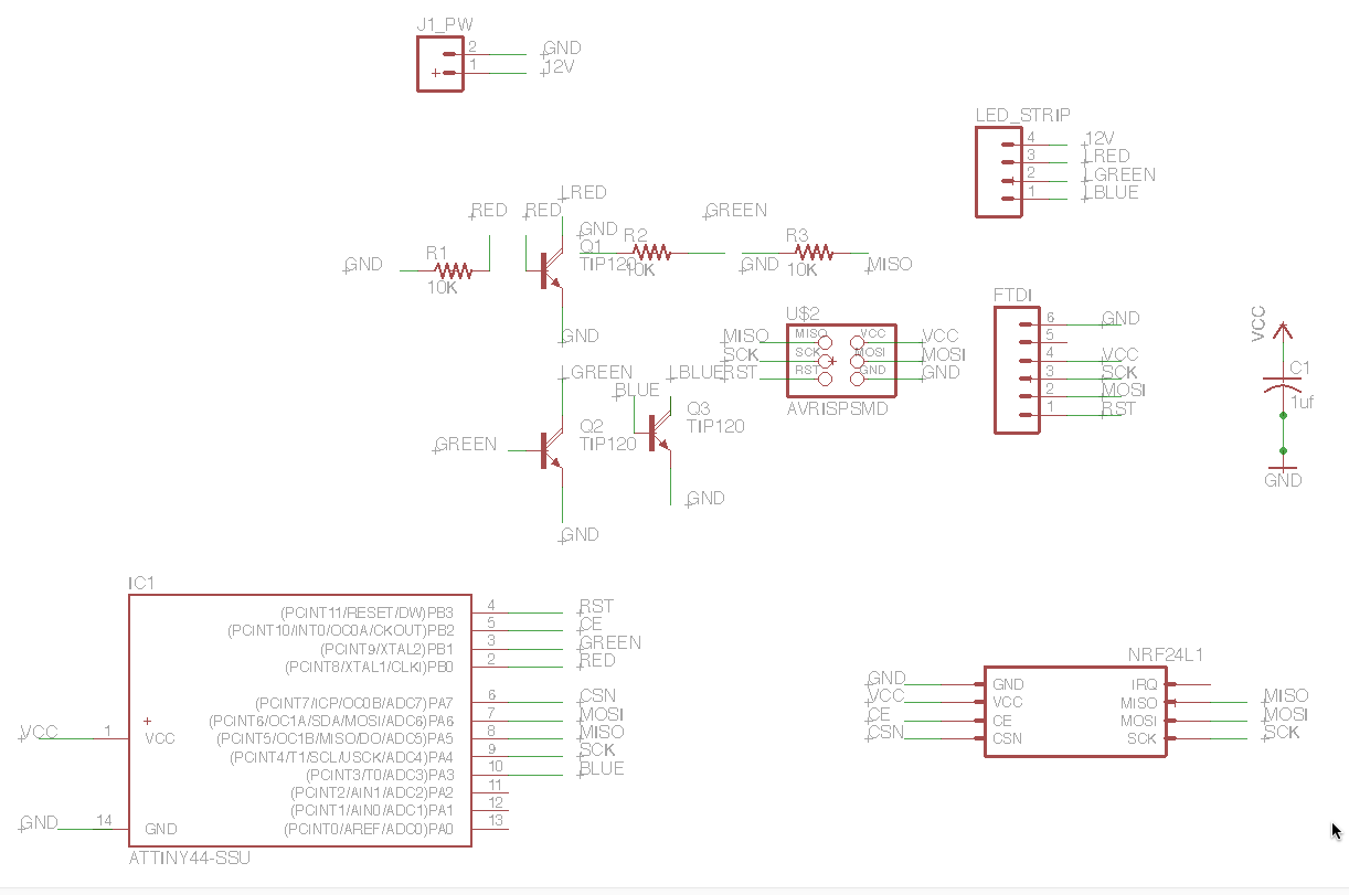
I made the schematic of a board with the mosfet included for connecting a led strip, FTDI and ISP and the 8 pins connector of the NRF2401L so is a big mess of routes so with my Knowledge I'm doomed, even is an easy one.
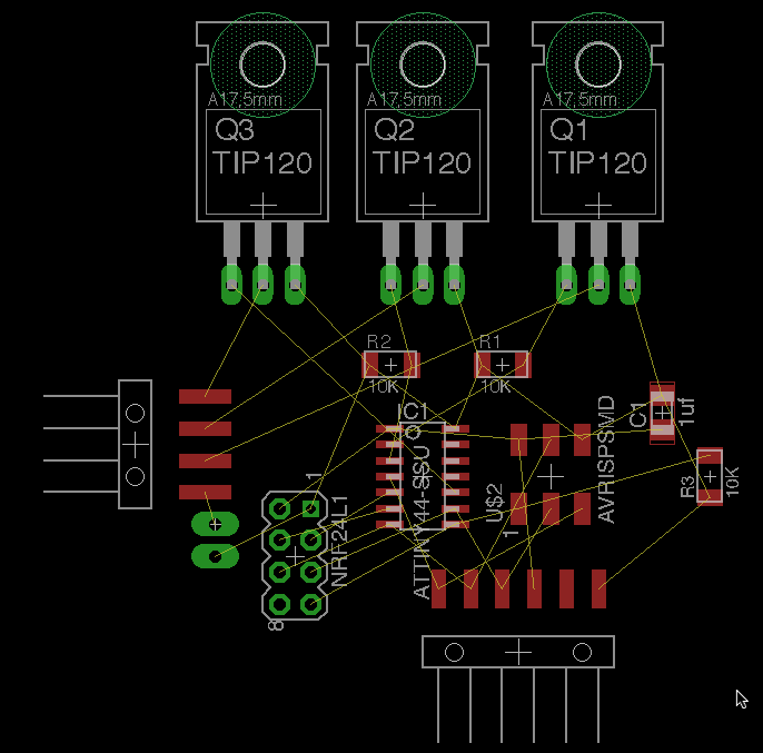
W2811 with nrf24l01
To try to have less connections I switch the led strip with 4 connections and all the mosfet in the board and 12v needed to a 3 pin connector for w2811 neopixels that have 5v current. But still same problems with rastnets.
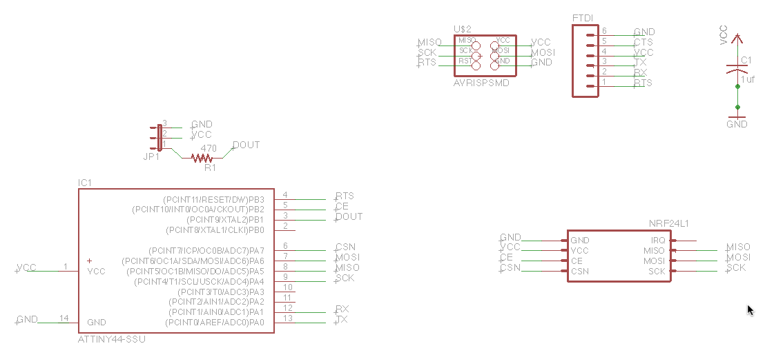
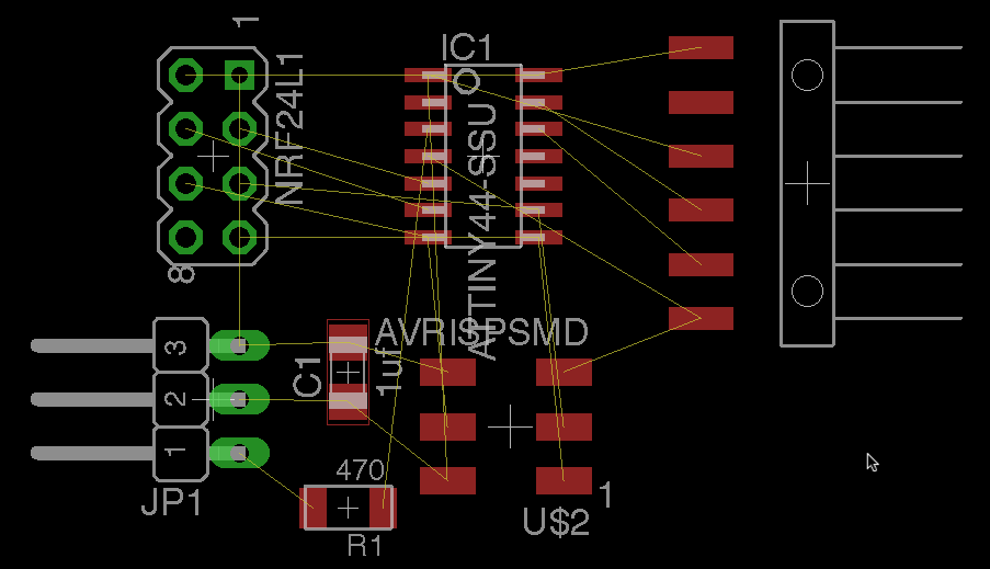
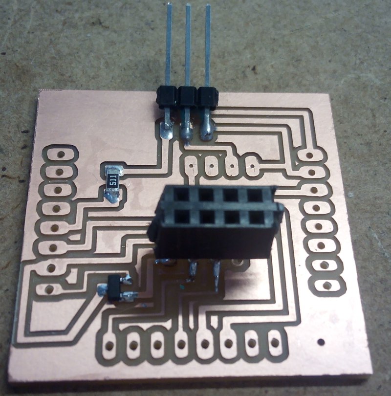
Shield nrf24l01 and Xbee for FabKits
Again I feel much more comfortable when I can make a shield, as I'm free of the microcontroller and all their paths and pins in the center, and you can start with pinout in the borders with several ground and vcc signals to connect and more clean.
The nrf24l01 works at a voltage of 3.3v and has a 2row of 4 male pins connector, that 7 of them have to be used.
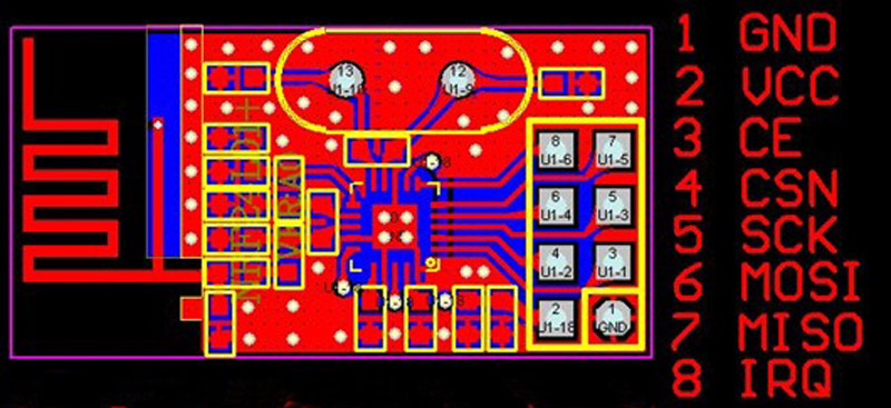
Most of the connections needed are in the bottom row if you look a Fabkit with the FTDI up.
The schematic is not very complex but you have included the power regulator that converts the 5v FTDI that I own a 3.3v that are safe for this or the Xbee.
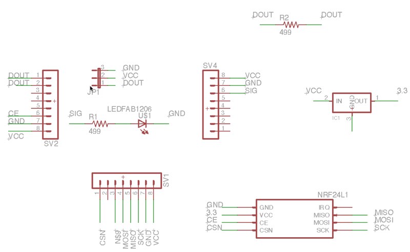
The shield also include a RGB Led connector that can also be used for SiG VCC GND sensors.
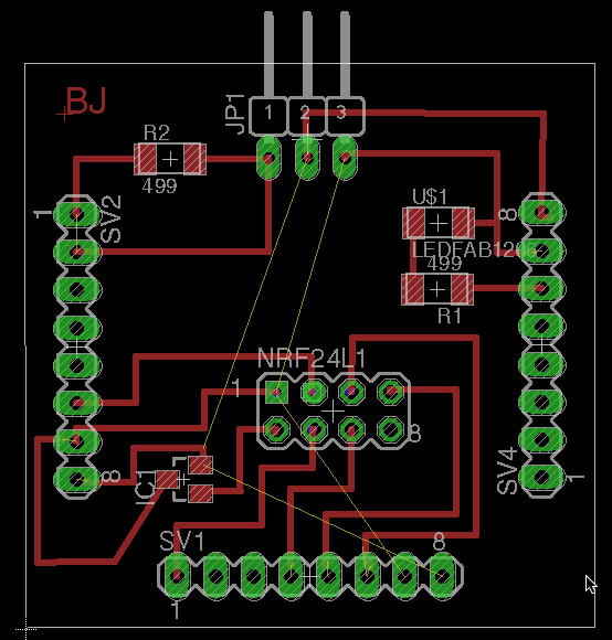
You can download Board and Schematic of this Fabkit shield.
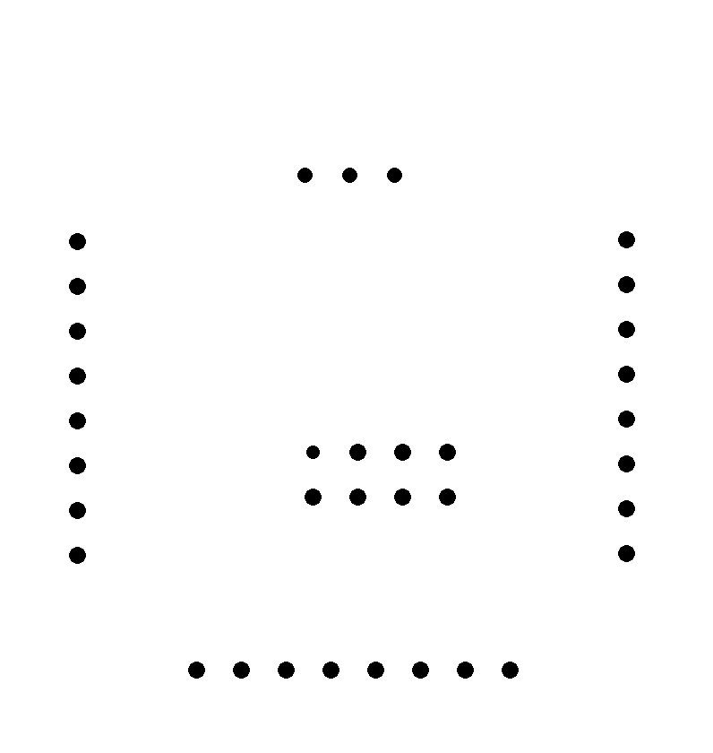
Here you have the PNGs for paths and holes, you can use any Fabkit cut png as is has the form factor, included V 0.2 and V 0.3

The shield is perfectly milled with every path well defined.
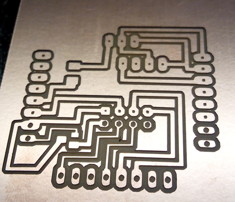
Here you can see a previous version that also include a 4 pads that was oriented for a Groove connector, but are not the correct paths and also are very near that the 3 Pin Led connector.
The library for working with nrf24l01 is available for downloading inside the Arduino IDE.

