Assignment 1: Testing the 3D printer Limits
Machine Specifications
- Layer resolution: up to 20 µm
- Build volume: 23 cm × 22.5 cm × 20.5 cm
- Position precision X Y Z: 12.5 µm × 12.5 µm × 5 µm
- Print speed: 30–500 mm/sTravel speed: 30–350 mm/s
- Filament diameter: 2.85 mm
- Nozzle diameter: 0.4 mm
- Card support: Stand-alone SD-card printing
- Feature: WiFi printing ready (future upgradeable)
- Software: Cura - Official Ultimaker
- Print technology: Fused filament fabrication (FFF)
- Frame dimension X Y Z: 35.7 cm × 34.2 cm × 38.8 cm (no filament)
- Frame dimension X Y Z: 49.2 cm × 34.2 cm × 55.8 cm (with filament)
- Operation nozzle temperature: 180-260 °C
- Operation heated bed temperature: 50-100 °C
- AC input: 100-240 V/~4 A/50–60 Hz/221 watt max.
- Power requirements: 24 V DC @ 9.2 A
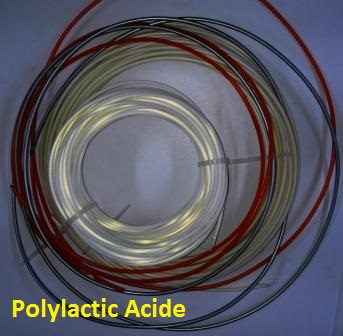
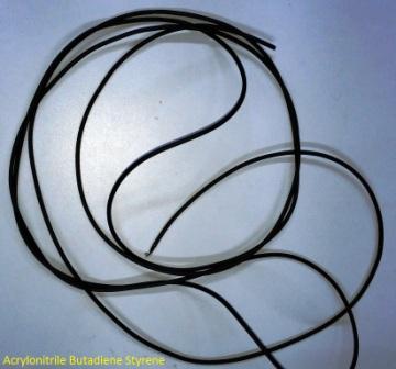
Different Color Materials Used in Lab
Testing the 3D printer Limits
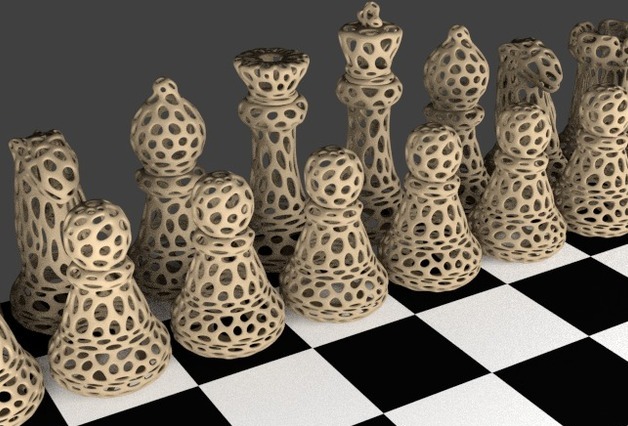
A group exercise is suggested to test the limits of the 3D printing machines. But if you have many printers in your Lab each one can try their own different test models.I have selected this model first from "Thingiverse" to test the limits. This model was created by Andreas Bastian to benchmark performance of desktop 3D printers.
These test geometries are designed to evaluate specific performance characteristics and motion systems in common low-cost FDM/FFF machines. Traditionally, layer height has been used as a proxy for resolution or quality, but it is a bit of an oversimplification of what is often termed "print quality". The below mentioned parameters can be tested with this model:
- Dimensional Accuracy
- Bridging Performance
- Overhang Performance
- Negative Space Tolerance
- Fine Positive Features Performance
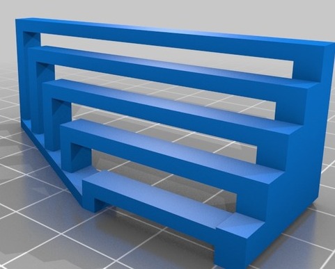
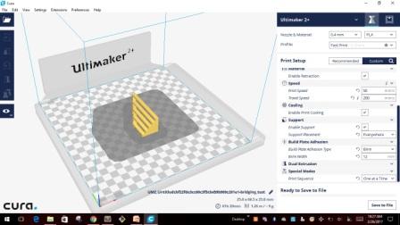
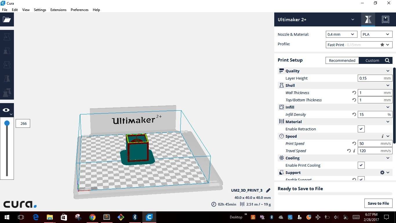
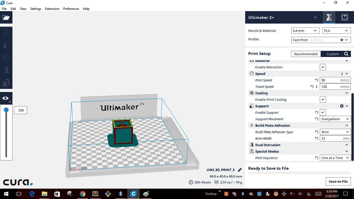
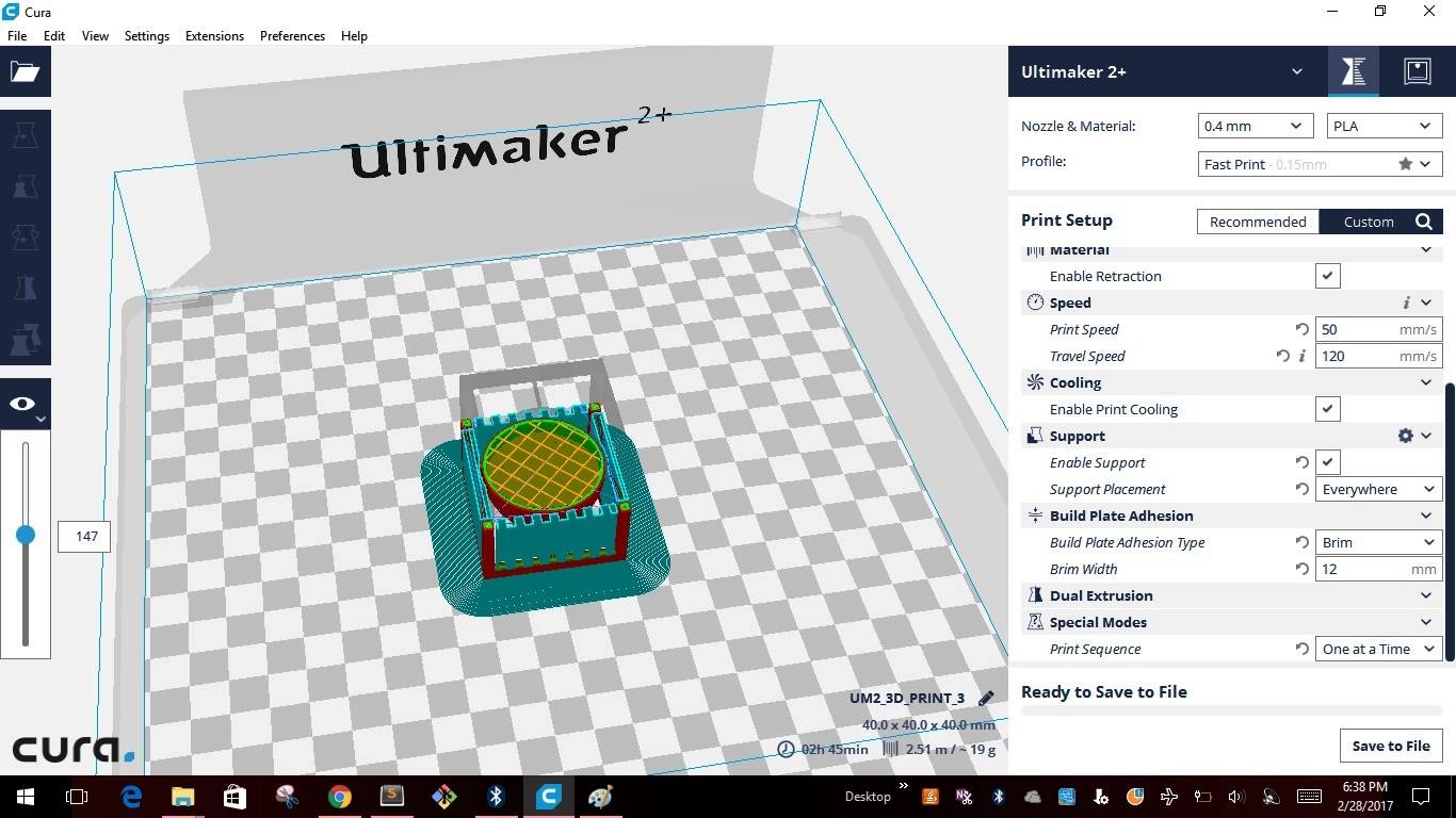
3D printing machines read .stl files to create the models. I used "CURA 2.4.0 an open source software available in "Ultimaker's" website. CURA gives you a plethora of options on how to print the part and also gives a visual preview of how the print would look like on a printer. After importing the model into CURA this is how the model looks like
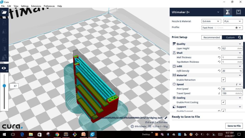
Like any other software CURA also has inbuilt pre-defined settings and also allows us to change the setting using the "Custom" settings. Below are the screen shots for different setting I used for creating the test model.
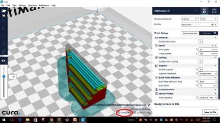
I saved the file to .stl file and exported the model into a removable drive "SD card" which is used to insert into the "Ultimaker 2+". At the bottom of the screen shows the time it will take to build the model with the custom settings. It took about the same time as shown in the CURA for the first model that I created. Then comes the turn to set the parameters in the machine.
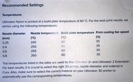
The below image shows some of the recommended settings for nylon material, however we can set the parameters as required for good quality output.
Before starting the print it is recommended to set the parameters of the machine. Also the first thing that need to be done is to check the nozzle diameter that is fixed in the machine. Based on the type & size of the model we can change the nozzle. The below image is showing different nozzles that come along with the machine. It is also equipped with a setting wrench, else we can use any available wrench in the Lab.
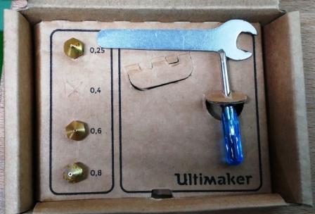
The following are the settings used for the first test model
- NOZZLE DIAMETER - 0.4mm
- SPEED - 50mm/s
- NOZZLE TEMPERATURE - 210 deg. Celsius
- BUILDPLATE TEMP - 60 deg. Celsius
- FAN SPEED - 100%
- MATERIAL FLOW - 100%
- RETRACTION - ENABLE
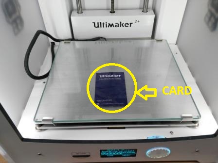
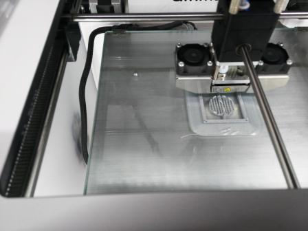
Before starting the print it also very important to level the "Building plate" on all the 4 corners. Using the "MAINTENACE TAB" option we can start doing the leveling of the build plate. By using endless knob of the machine bring the nozzle of the machine till the bed is 1mm away from it. This can be done using a 80GSM paper card as shown in the below image.
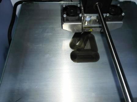
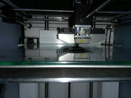
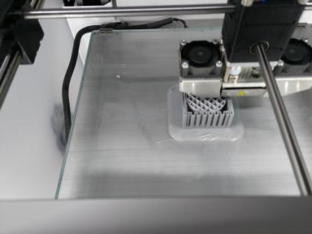
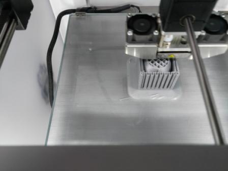
The machine will display how to proceed further while doing the leveling. After completing the leveling of build plate we can proceed with the printing of the model. Below images were captured during the printing in process.
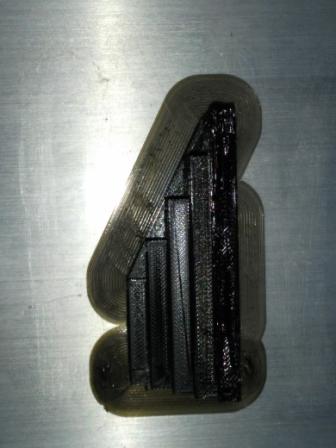
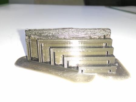
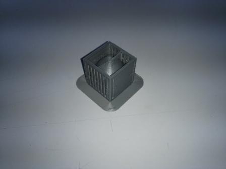
- The following are the observations made
- Size : The object size is 25mmx66.5mmx25mm : Size is correct with slight variation
- Finish: Not so smooth
- Surface : Looks smooth as it should be
- Color : Same as the input material
- Supports: The default support settings was holding the overhang good
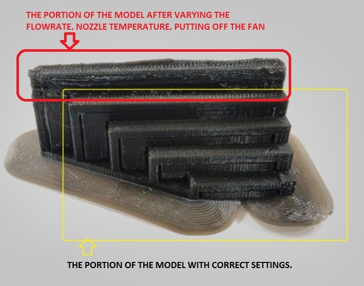
- The following are the changes made in the settings
- NOZZLE DIAMETER - 0.4mm
- SPEED - 60mm/s
- NOZZLE TEMPERATURE - 200 deg. Celsius
- BUILDPLATE TEMP - 50 deg. Celsius
- FAN SPEED - 0%
- MATERIAL FLOW - 130%
- RETRACTION - ENABLE
- The following are the observations made
- Size : The object size is 25mmx66.5mmx25mm : Size is correct with slight variation
- Finish: Not so smooth
- Surface : Looks smooth as it should be
- Color : Same as the input material
- Supports: The default support settings was holding the overhang good
Assignment 2: Model - Sphere in Cube Cage
This week after testing the limits of the 3D printer, we had to individually design & test the model in 3D printing. The criteria was to design a model which cannot be made using any of the subtractive manufacturing process. This is the first model that I made in Solidworks, very simple but effective to meet the criteria.I felt this design is very simple and good enough to complete this assignment. The idea is to hold the sphere inside the Cube cage. Initially I created the sphere of size 40 & then created the cage around the sphere. I saved the .sldprt file to .stl file in Solidworks. Transfered the .stl file to CURA2.4.0 as shown in the images below.
The pictures were taken during & after printing was completed
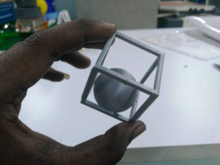
After completing the printing I measured the dimensions of the cube and found that there is difference of 0.20mm on all sides of the cube
Assignment 3: 3D Scanning
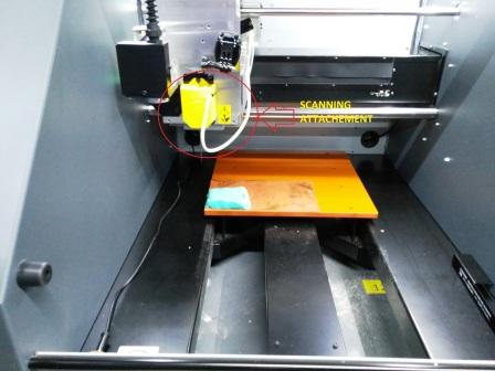
This week I also did the 3D scanning of a small model. I used Roland MDX- 40-A machine with a scanning attachment to do this exercise. This is the same machine used to do the milling of PCB board assignment with milling attachment. Below image shows the scanning attachment
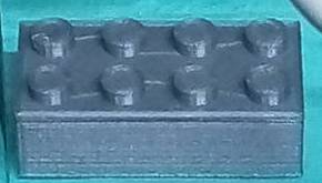
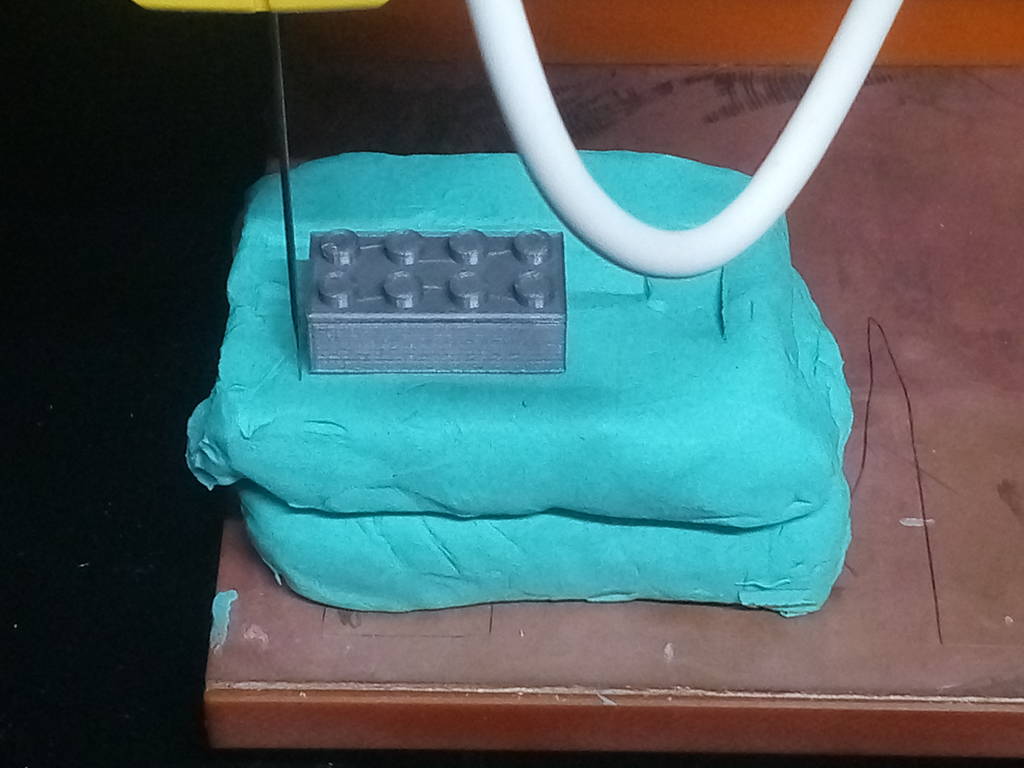
The below picture is the model I used to do 3D scanning
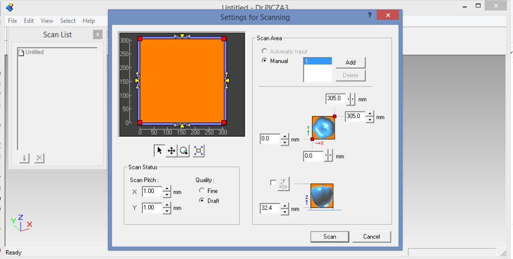
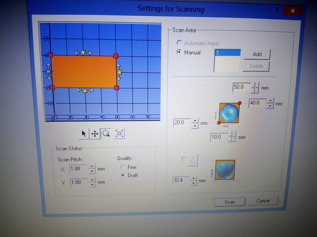
I used the Dr PICZA software to operate the 3D scanning available in the FabLab Bombay. Dr.PICZA3 is a program that digitizes scanning operations. The program enables you to adjust the scanning pitch, area, or mode, providing advanced users with more options and control over the scanning process. Using a Roland scanner device you can easily get a 3D object scanned. Doing the 3D scanning activity was new & an interesting activity. The below shows the settings page of the Dr.PICZA3
I placed the moldclay on the machine bed to support the model to be scanned. On top of the moldclay I placed the model at a random position in X & Y axes.
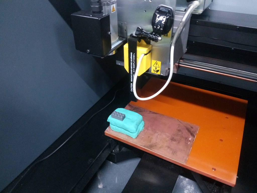
After placing the model I checked the distance of the model w.r.t the origin of the machine using a vernier scale in both the X & Y axes.
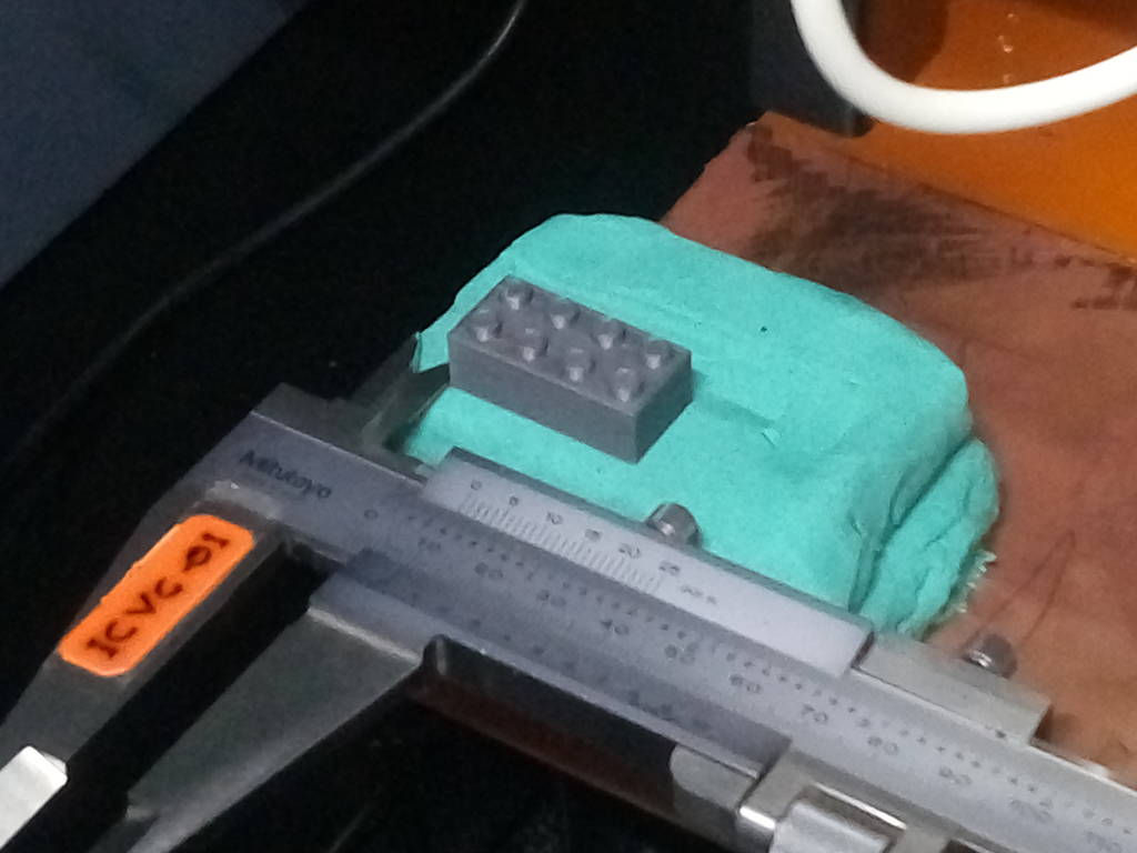
I input these values in the X & Y tabs of the settings page of the software
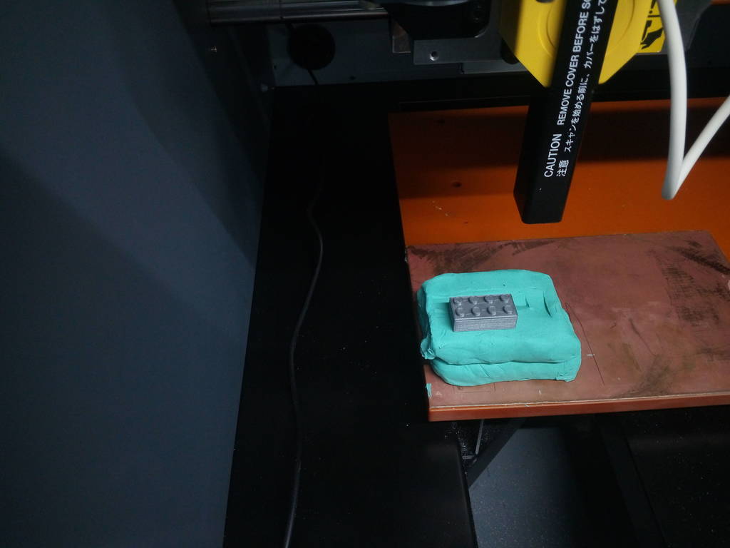
For the Z axis, as shown in the below picture place the pointer approximately on the highest point of your model. Double click on the pointer so that the touch probe of the machine comes & touches the highest point on the model physically on the machine. Similarly to check the lower left bottom & the upper top right of the model double click on the red tabs circled in the image.
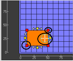
As you are doing this the touch probe comes to the origin as shown in the below image
After ensuring that the limits of the touch probe are around the exteriors of the model to be scanned I set the resolution of the scanning to 1mm X 1mm & started the scanning.
Below is video showing the scanning in process. Video Link
Below are the pictures that the software generates after scanning is completed. This file can be saved to .stl or .dxf formats. I saved my model to .dxf format
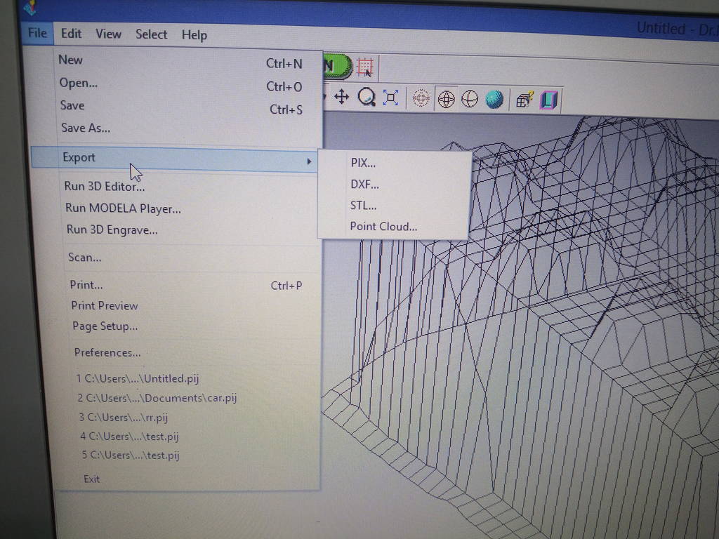
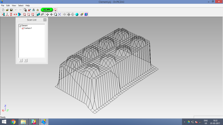
Below is video showing the scanning in process. Video Link
3D Scanning from Clement Burga on Vimeo.
learnings of this week
- 3D Printing
- Learnt to operate the Ultimaker 2.0 machine for 3D printing objects.
- This machine can be used only for prototyping objects which can be used for study purpose & also for experimentations..
- Learnt to work with Cura for setting the parameters of 3D printing. 3D Scanning
- Overall view of 3D scanning is that the process we used is not that accurate to use it for further applications .
Files to download

This work is licensed under a Creative Commons Attribution-NonCommercial-ShareAlike 4.0 International License.