Design for Fab Lab Project
The real life setup is way too large to be designed & developed in Fab Lab. I had to create a prototype model of the real life model by scaling down the equipment size. At the same time I had to create a working model with all the functionalities displayed in the final project by projecting all the array of knowledge gained in the Fab lab. Hence I designed the scaled down model in Solid Works. The details will be furnished below.
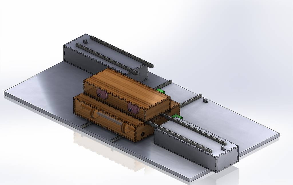
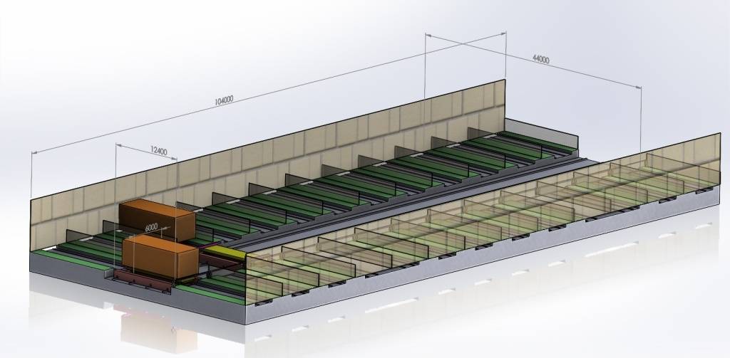
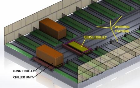
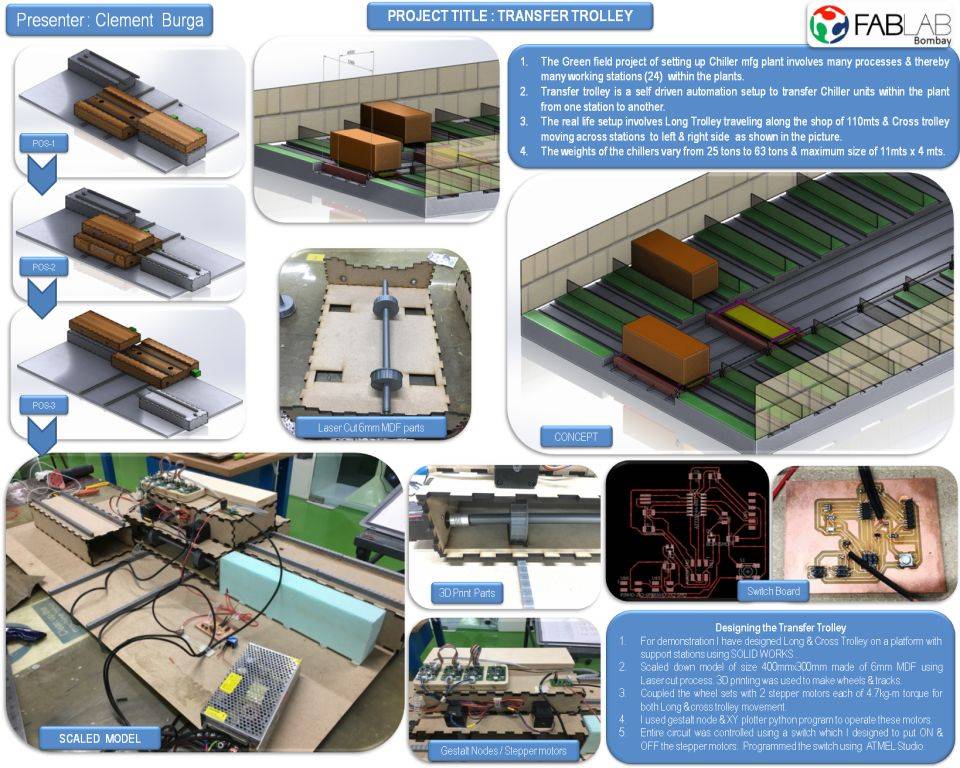
The transfer trolley is a self driven automation setup to transfer Chiller units within the plant from one station to another.
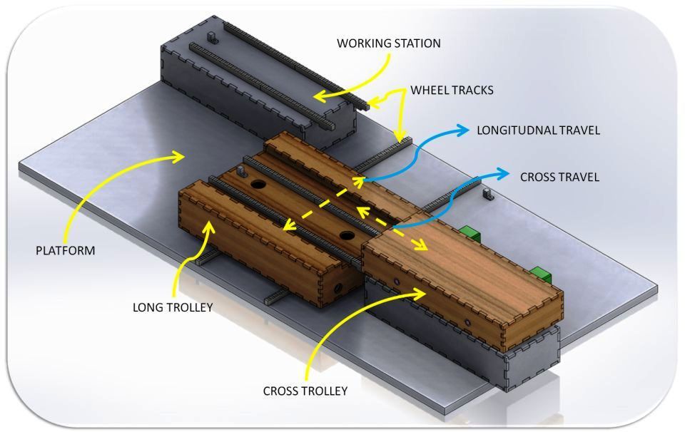
- For demonstration I have designed Long & Cross Trolley on a platform with support stations using SOLID WORKS .
- Scaled down model of size 400mmx300mm made of 6mm MDF using Laser cut process. 3D printing was used to make wheels & tracks.
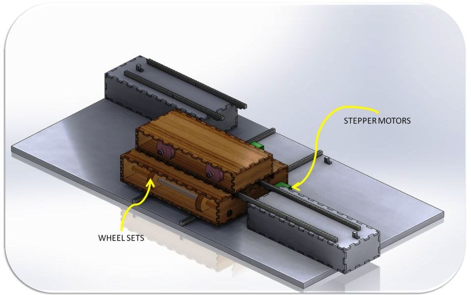
- Coupled the wheel sets with 2 stepper motors each of 4.7kg-m torque for both Long & cross trolley movement.
- I used gestalt node & XY plotter python program to operate these motors.
- Entire circuit was controlled using a switch which I designed to put ON & OFF the stepper motors
- Programmed the switch using ATMEL Studio.
processes covered in this project
- Computer Aided Design - Solid Works & AutoCAD
- Computer-Controlled Cutting - Laser Cutting
- 3D Printing
- Electronics Design - Eagle
- Computer-Controlled Machining - PCB Milling
- Embedded Programming - ATMEL Studio, Arduino
- Mechanical Design - Fabrication & assembly
- Input Devices - Switch Board
- Output Devices - Stepper Motor
- Interface & Application Programming - Gestalt node & switch board
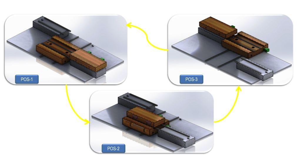
Explaining the Design
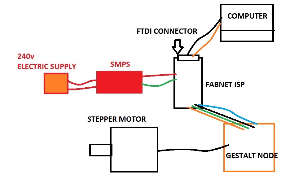
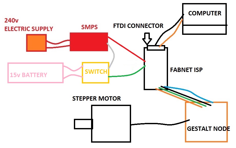
I have explained the working cycle of the Transfer trolley in below picture. For this project I will program 4 stepper motors with the gestalt nodes available in our lab. I will design a switch to control the ON-Off of these stepper motors.
I have designed the entire model using Solid works. The important thing was to keep the design simple, lite & economic.
For this purpose I choose to make all the structure using 6mm MDF. These individual parts will be the Laser cut. I then converted all the individual files of solid works to .dxf format for laser cutting.
Laser Cutting Parts
After doing assignments of laser cut previously it was easier for me to decide the fitting tolerances to be provide for laser cut. But here I have used a tolerance of +0.2 per side instead of +0.15 previously used for my laser cut assignment. This was because I wanted rigidity in the structure once the assembly was done.
The laser cutting was done at our supplier's place who cut all the parts as per the dxf files provided by me. All the individual files of the design can be downloaded at the links mentioned below in this page.
3D - Printing
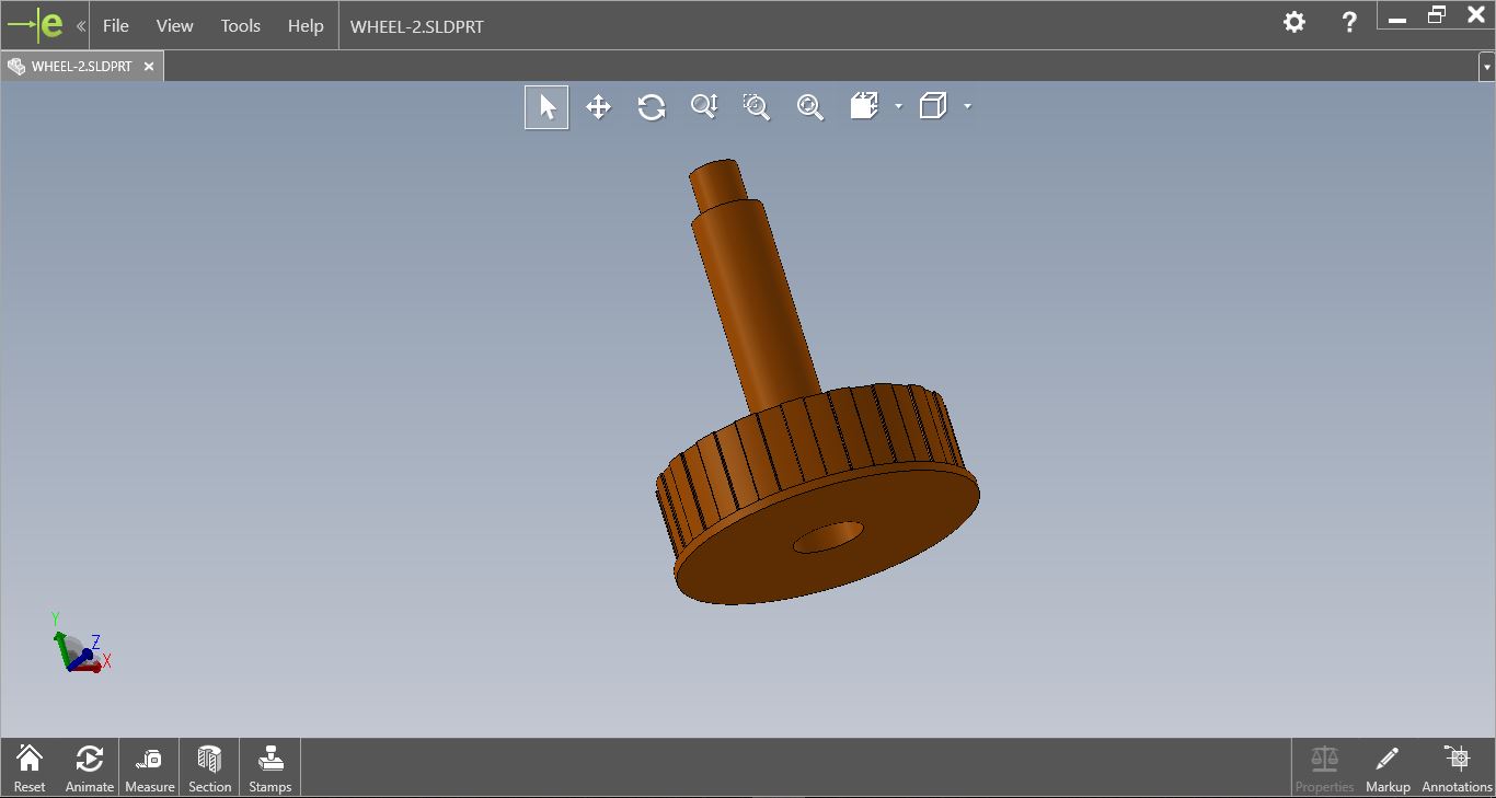
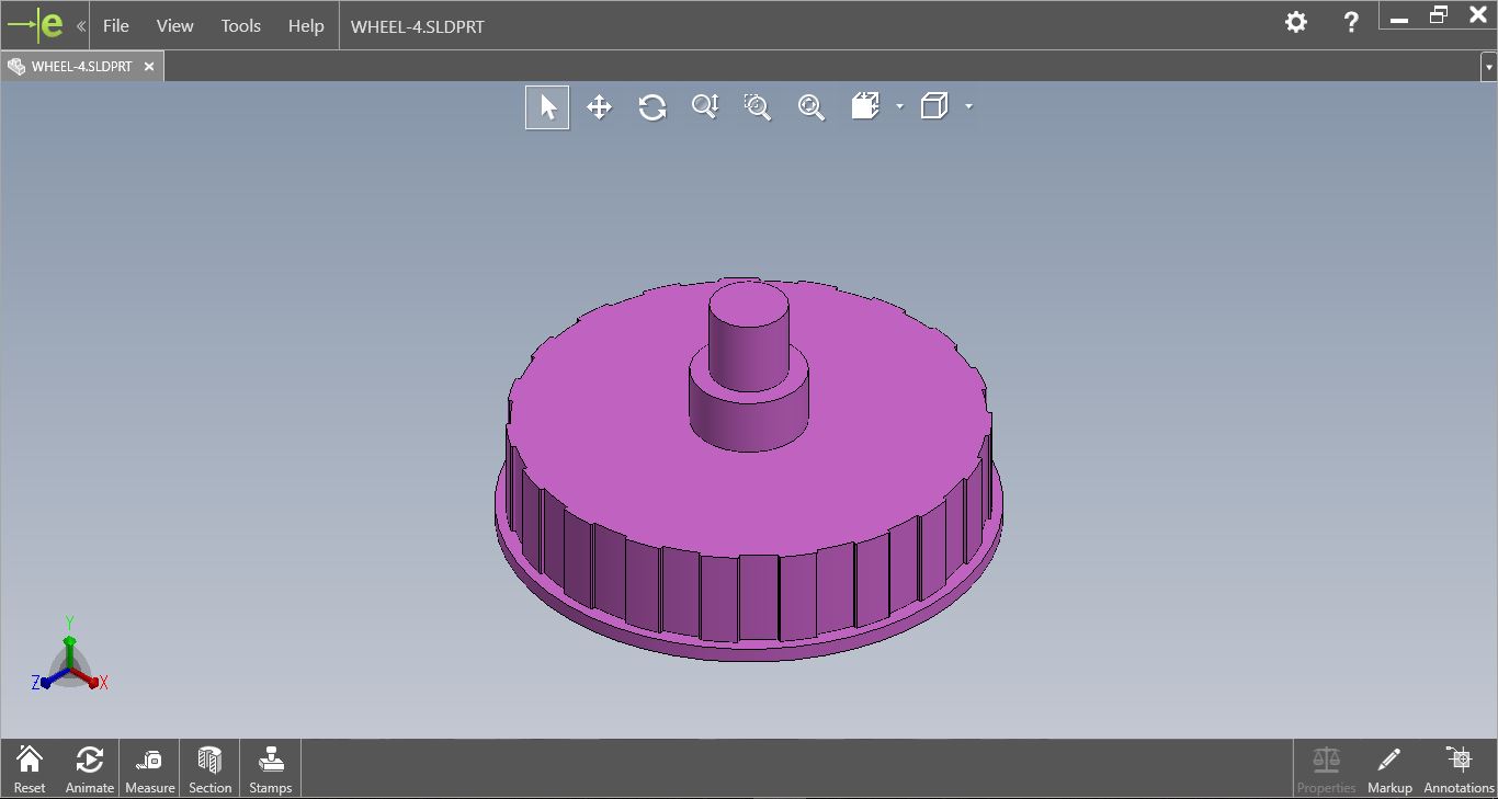
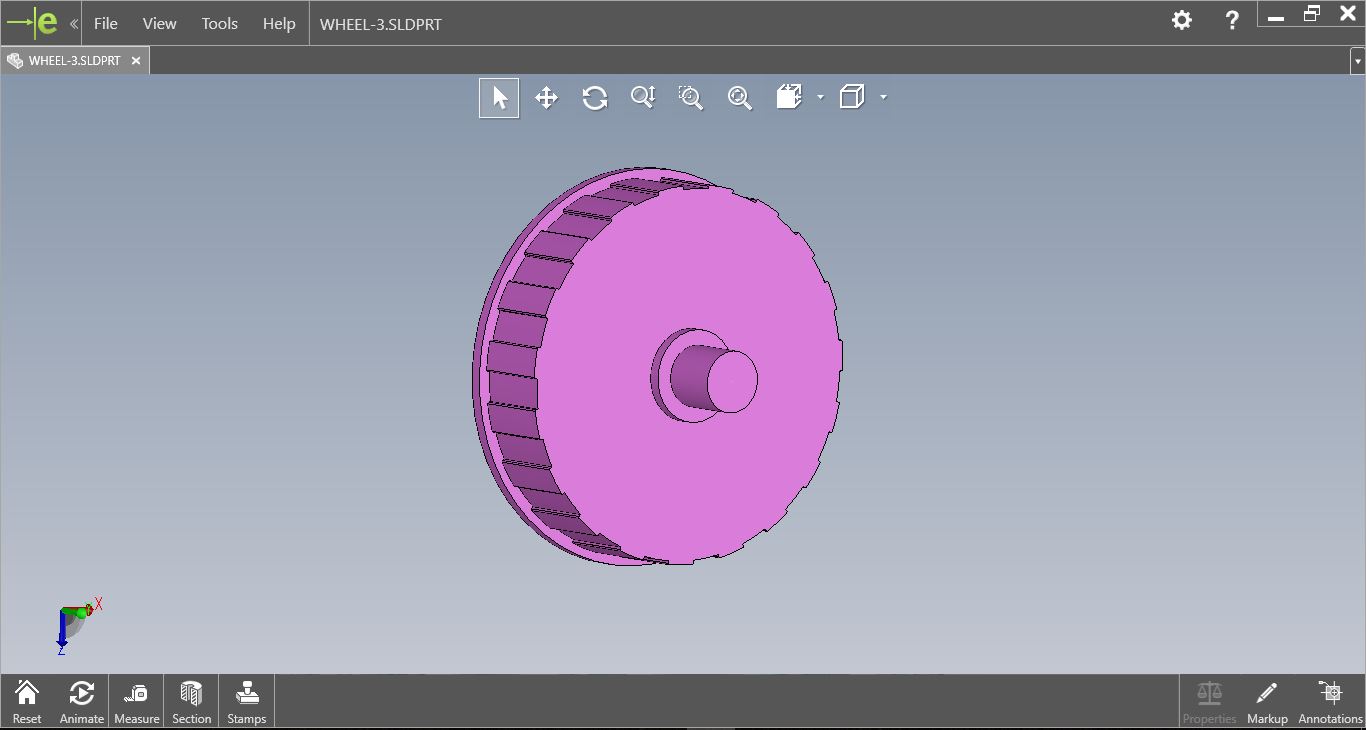
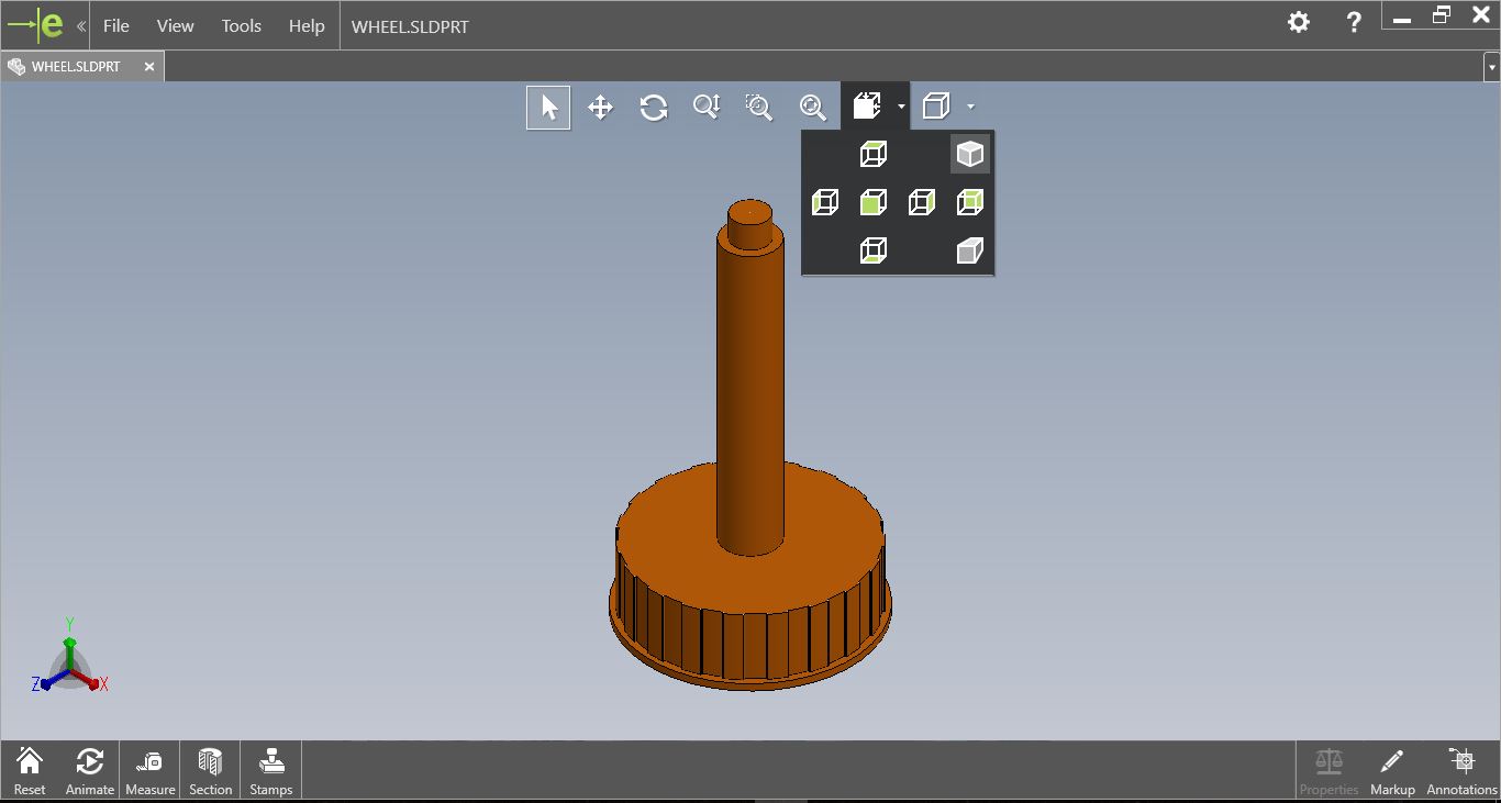
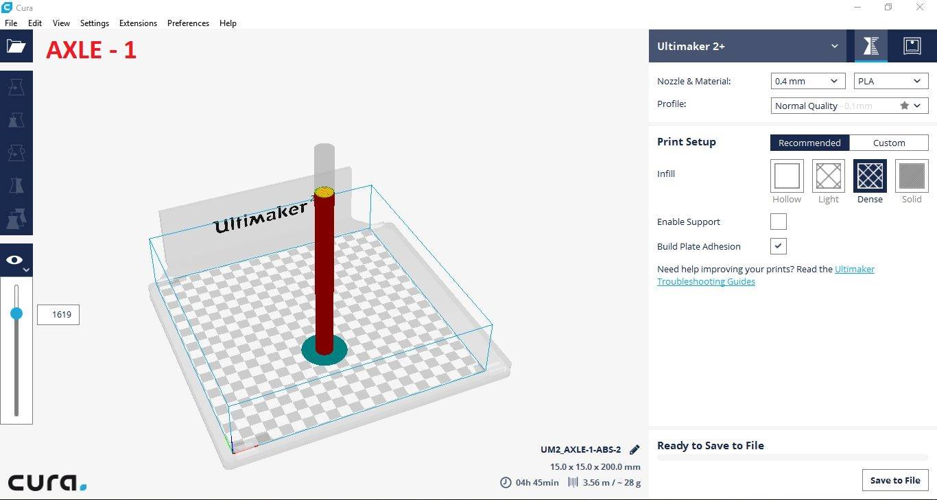
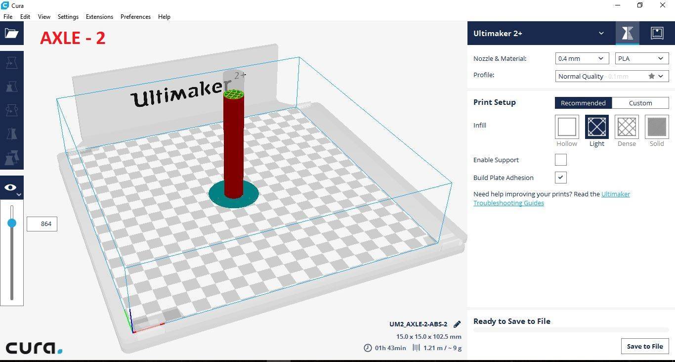
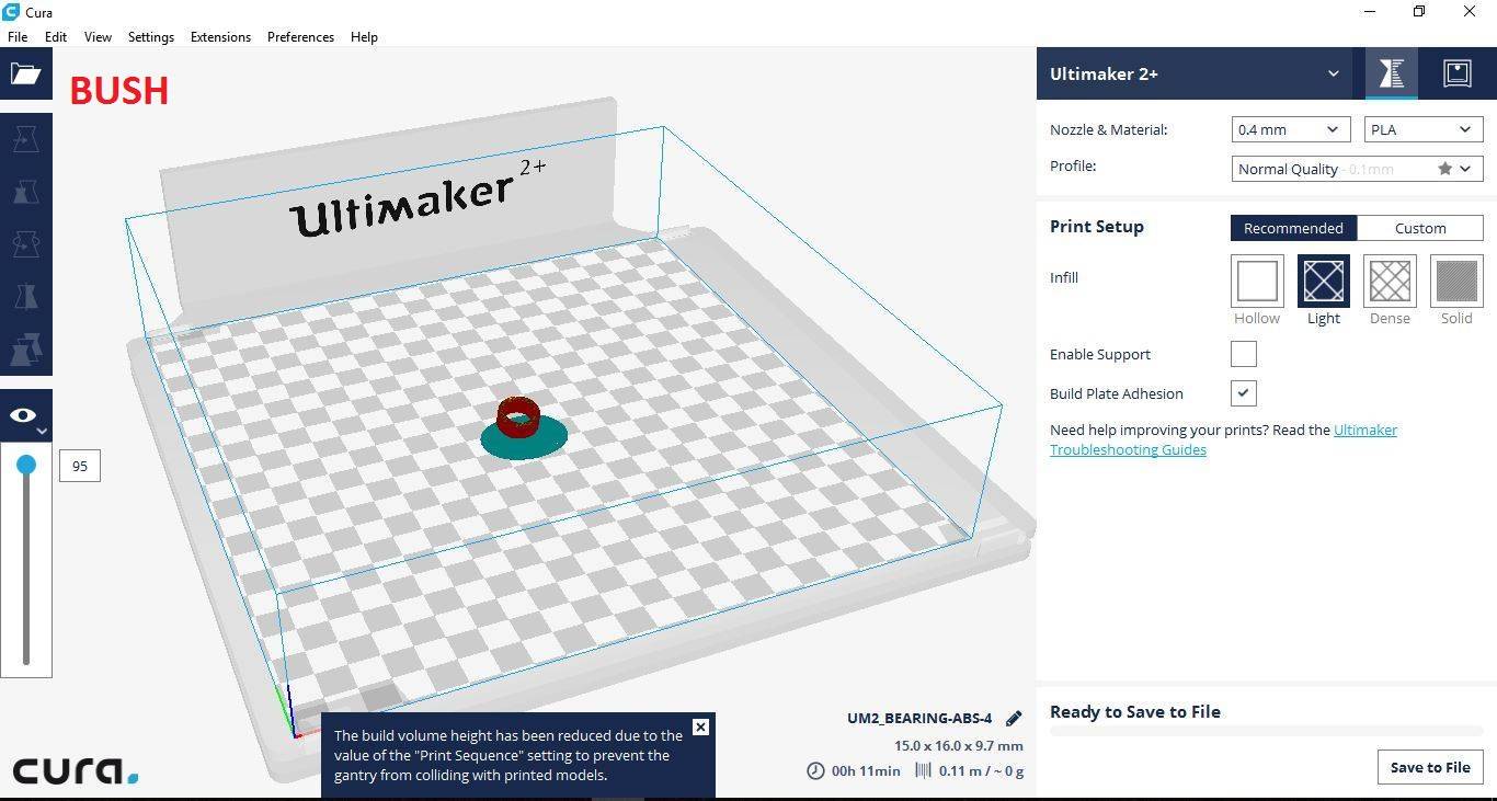
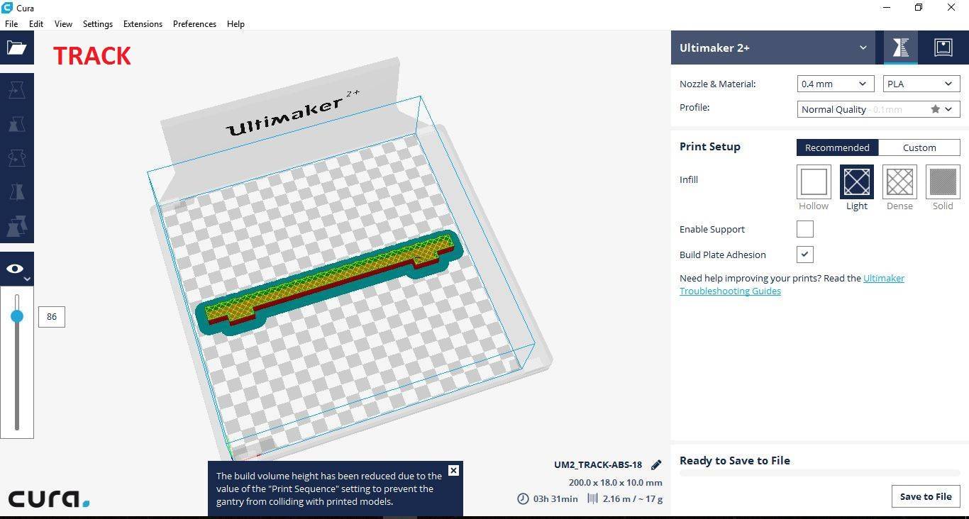
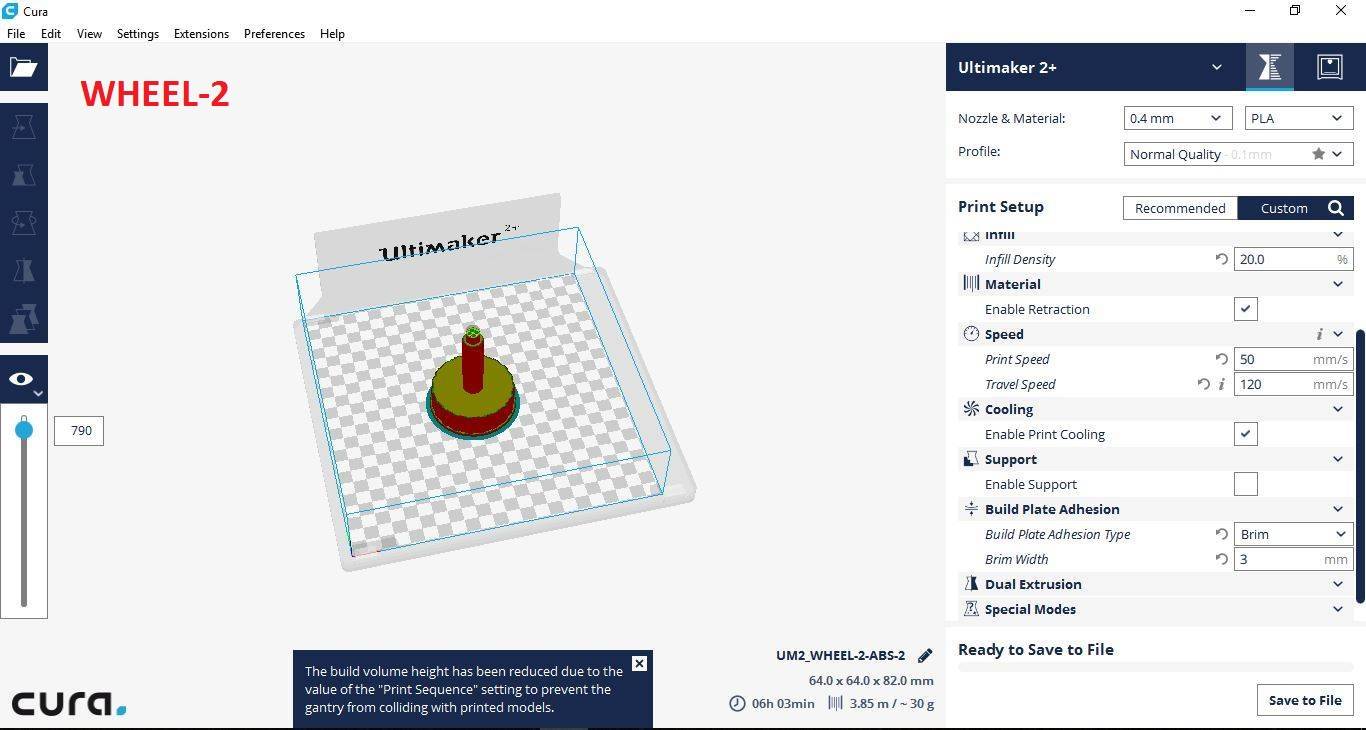
As explained before, I designed all the wheel sets using Solid works. To make these wheels I used 3D printing. First I converted all the individual files of Solidworks to .stl & imported them into CURA2.0.
The below images show the models in Solidworks
The settigs used to 3D print are as given below:
- NOZZLE DIAMETER - 0.4mm
- SPEED - 60mm/s
- NOZZLE TEMPERATURE - 200 deg. Celsius
- BUILDPLATE TEMP - 50 deg. Celsius
- FAN SPEED - 0%
- MATERIAL FLOW - 130%
- RETRACTION - ENABLE
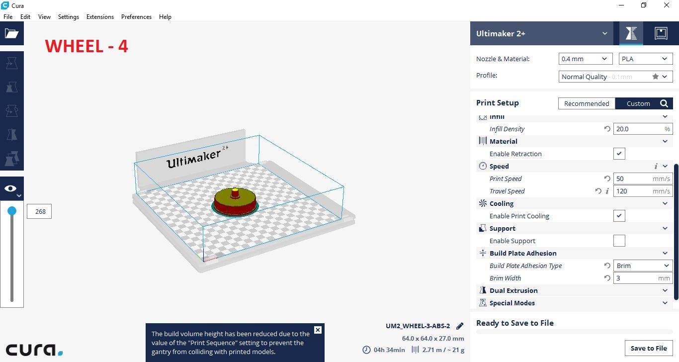
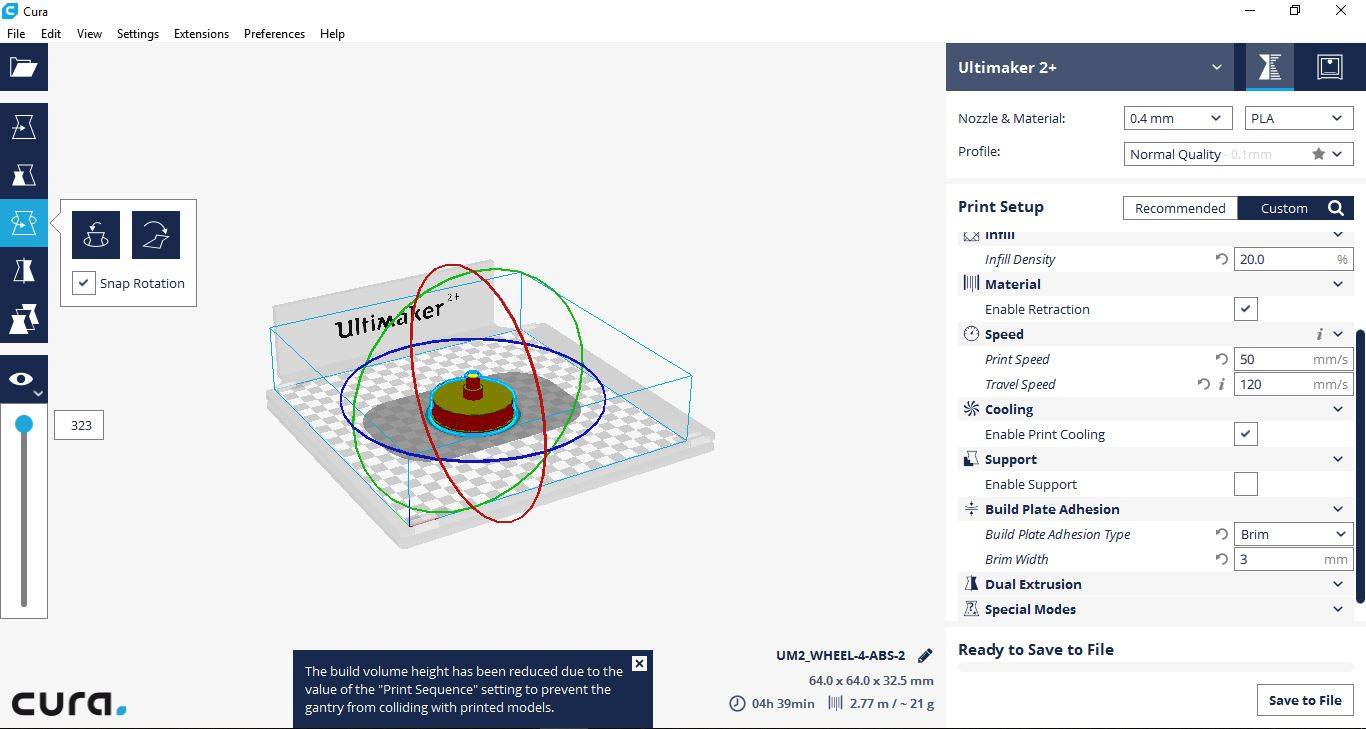
The below images show all the files after importing to CURA 2.0 before 3D printing.

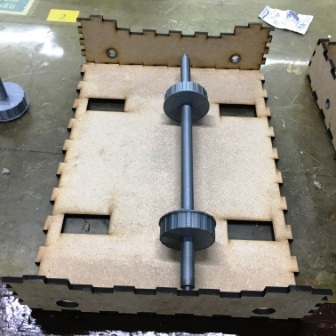
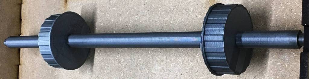
The below images show the wheel set assembled after 3D printing.
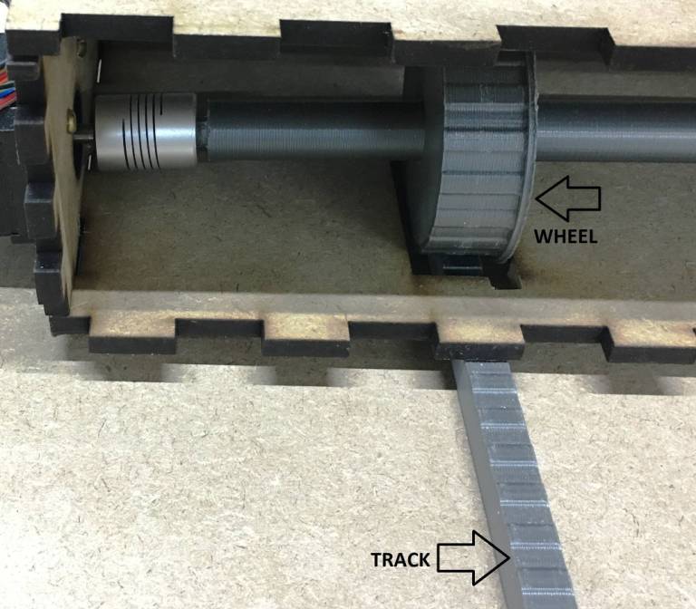
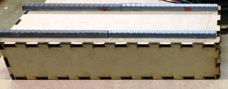
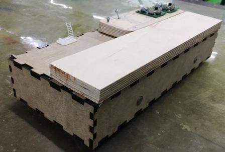
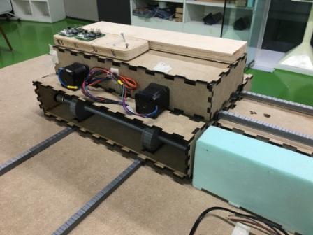
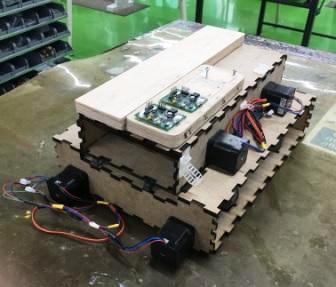
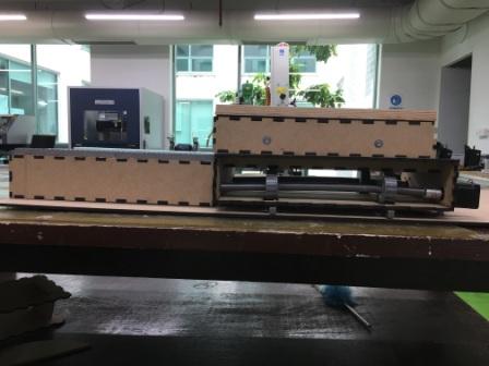
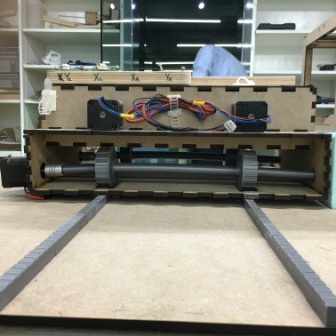
Below images show after the mechanical assembly is completed
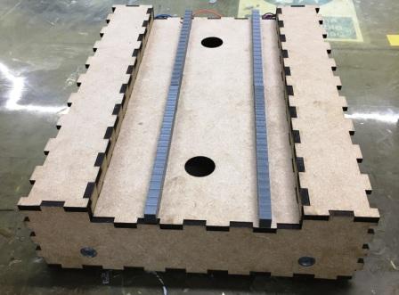
Below image shows the alignment of the wheels done with the track
Electronics design
Step 1: Installing gestalt node
I will be using stepper motor which I have previously used for MTM assignment of group activity. In total I will be using 4 stepper motors & 4 gestalt nodes for my project. I will explain the detailed process of how I went through the operation of stepper motor using gestalt nodes.
I first went to this site GIT Hub to download the package of gestalt node as shown in the below image.
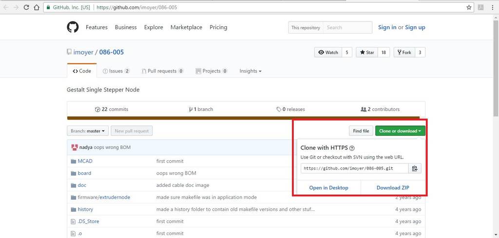
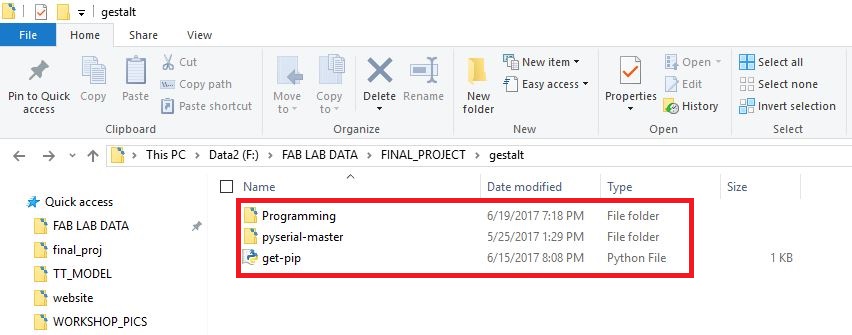
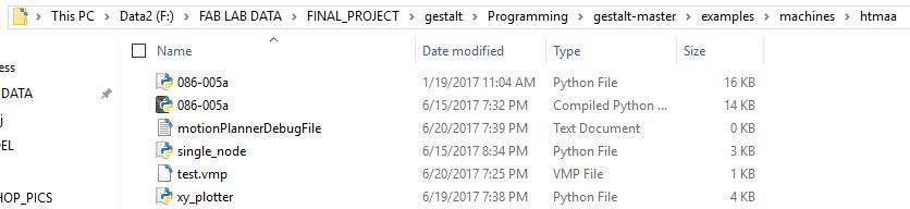
The following folders will be present after downloading the package.
Install Python 2.7 —not Python 3.4. There are numerous differences between Python 2 and 3, and Gestalt has been built with Python 2. Make sure to add Python to your PATH so you can run it from a command prompt.
Install pySerial . There are many ways to do this, but perhaps the most “correct” way to do it is to first install pip, the Python package manager. pip comes with Python 3.4 and later, but since we’re on Python 2, we will have to go through a jankier process.
First, download this script for installing pip. (It’s not a virus.) Then, run the following commands:
              python get-pip.py
              python -m pip install pyserial
(python -m pip is an alias for just pip on Windows.)
Build the gestalt software. First, check out a copy of the repository. Then, go to the directory and run
python setup.py install

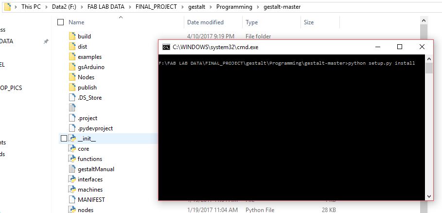
This builds the code and installs it locally so you can import gestalt from Python code. Otherwise doing this will throw an error, and you may be tempted to make a bunch of copies of the files to try and fix it, which is sure to cause more havoc.
Test! At this point you should be able to get a basic two-node, two-axis machine running with the provided xy_plotter.py demo file.
Step 2: To Use the gestalt node
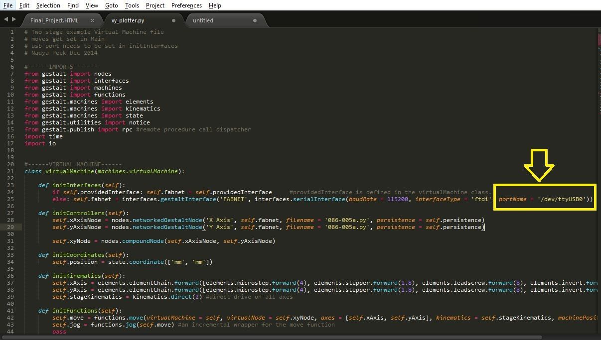
In any of the text editor open the file xy_plotter python file & pre written code can be seen.
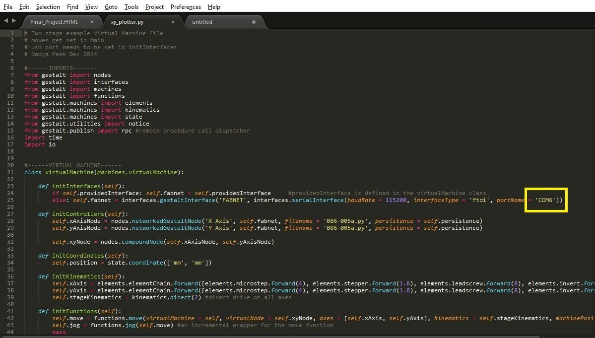
The immediate thing to do is to change the default COM port from /dev/ttyUSB0 to the COM port as can be seen in respective Device manager of the particular laptop. Here in my laptop its COM6
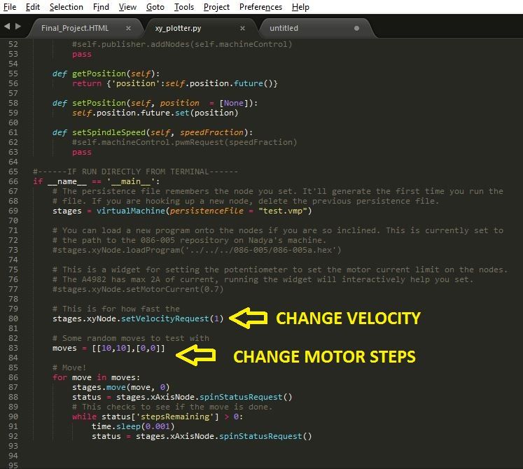
The next step is to change the value of the velocity & steps of the stepper motor as per our requirement.
Then go to the directory & open command prompt window & type the below command
python xy_plotter.py
Before hitting the enter button ensure that the connections to the gestalt node are made as shown in the below image. Also ensure that the power supply is ON before hitting the enter button.
I ensured that all the 4 steppers motors are in good condition before assembling them to my long & cross slides.
Step3: Design a ON-OFF switch
Only using the standard gestalt nodes & the pre written code is not enough for completing the project work of Fab Academy. It is important that I design an input device to cover up the prescribed topics. Hence I designed a switch which can put ON & put OFF the supply from the SMPS going to the stepper motors. Also this switch can be used as an emergency stop button if there is any mal-function in the working of the stepper motors.
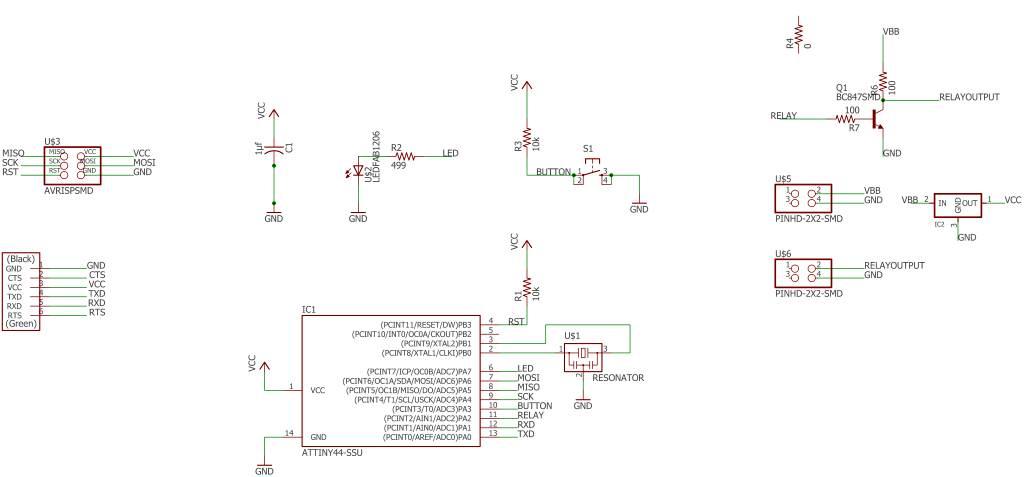
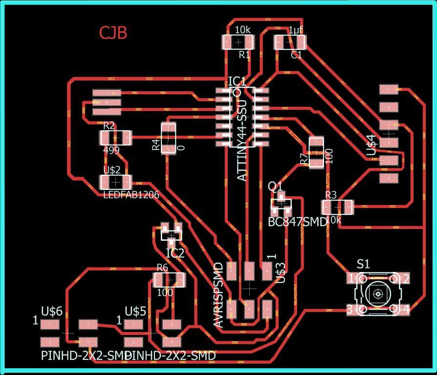
Here I used ATtiny44 micro-controller & BC847SMD to program the board. I used ATMEL studio to write the code for this
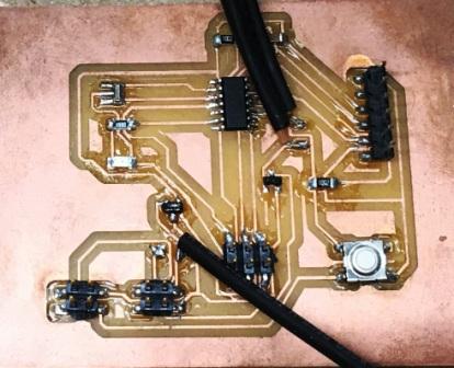
Then I wrote the code for operating this switch in ATMEL studio. After writing the code I downloaded the program to the micro controller through the Arduino Uno.
#define F_CPU 1000000  //Define clock speed as 1Mhz
#include     //Import header file required for AVR micro-controllers
#include   //Import header file required for delay function
int main(void)
{
DDRA = 0b10000100;  //set PA7 & PA2 as output & all other pins as input
int flag;
flag=1;
//PORTA &= ~(1<<7); //Set PA7 low (Make LED OFF)
//PORTA |= (1<<2);

while (1) //Repeat the below actions continuously
{
if((PINA & (1<<3))==0b00000000 && flag==1)
{
PORTA ^= (1<<7); //Set PA7 high (Make LED ON)
PORTA ^= (1<<2);
flag = 0;
}
else if ((PINA & (1<<3))!=0b00000000 && flag==0)
{
flag = 1;
}
}
}
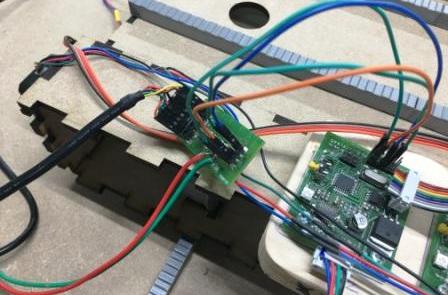
Now the important task was to integrate this switch board with the circuit I already had showed above.
The below image shows how I integrated the board with the gestalt setup.
The testing of the switch can be seen in the video
SWITCH_TESTING from Clement Burga on Vimeo.
Once the testing is done, then I moved on to connect the serial port to my laptop & run the python command to operate the stepper motors. I modified the xy plotter program as per my requirement which is seen below. I have only displayed the area of the code I changed, but the rest of the program can be downloaded provided in the links below.
Here I have connected 2 stepper motors to one single gestalt node & other 2 stepper motors to separate gestalt nodes. Hence the program has only 3 nodes as can be seen below.
# This is for how fast the
stages.xyNode.setVelocityRequest(1)

# Some random moves to test with
#moves = [[0,-12,-12],[-10,-12,-12]]
#moves = [[0,-12,-12],[-19,-12,-12],[19,-12,-12]]
moves = [[19,0,0],[19,12,12],[19,0,0]]
# Move!
After changing the code the python asks to identify the stepper motors. Upon prompting we need to identify the required stepper motors by pressing the tactile switch as shown in the below image.
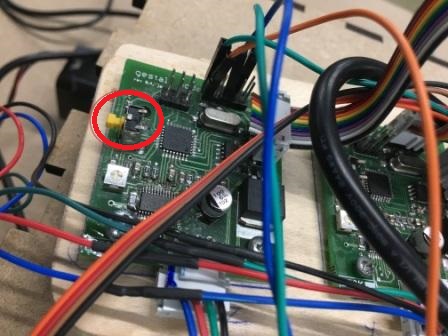
As soon I identify the stepper motors, the motors operate in the required direction.
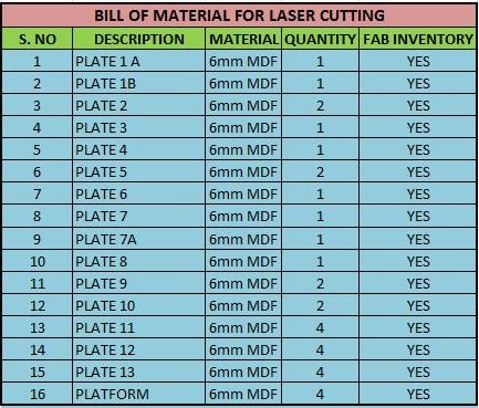
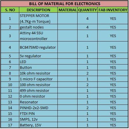
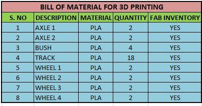
Bill of Material
Find below the Bill of material used in this project
My Final Project Slide
Final Project Video
PROJECT VIDEO from Clement Burga on Vimeo.
Files to download

This work is licensed under a Creative Commons Attribution-NonCommercial-ShareAlike 4.0 International License.