Assignment : Use processing to interface with the LED board
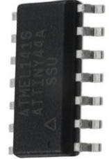
AVR - ATtiny 44 Micro-controller
A micro-controller is a small computer (SoC) on a single integrated circuit containing a processor core, memory, and programmable input/output peripherals. Program memory in the form of Ferroelectric RAM, NOR flash or OTP ROM is also often included on chip, as well as a typically small amount of RAM
The documentation for Atmel’s ATtiny44A MCU is a whopping 286 page pdf. Electronics was never my cup of tea. But I had to go through the data sheet to understand what the micro-controller is capable of doing & how it does.
Some of the features of the ATtiny 44 are as listed below:
- High Performance, Low Power AVR 8-bit Micro-controller
- 120 Powerful Instructions – Most Single Clock Cycle Execution
- 256/512 Bytes of In-System Programmable EEPROM
- Data Retention: 20 years at 85°C / 100 years at 25°C
- On-chip Analog Comparator
- Programmable Brown-out Detection Circuit with Software Disable Function
- Operating Voltage: – 1.8 – 5.5V
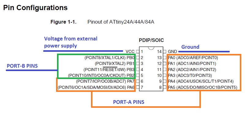
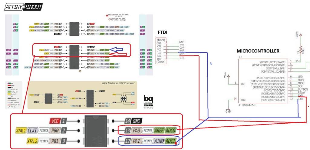
The Pin Configuration and Pin Descriptions in Section 1 are important - PighiXXX has created very nice color-coded pin-out diagrams for many processors including the ATtiny family, including pin mapping for the Arduino IDE:
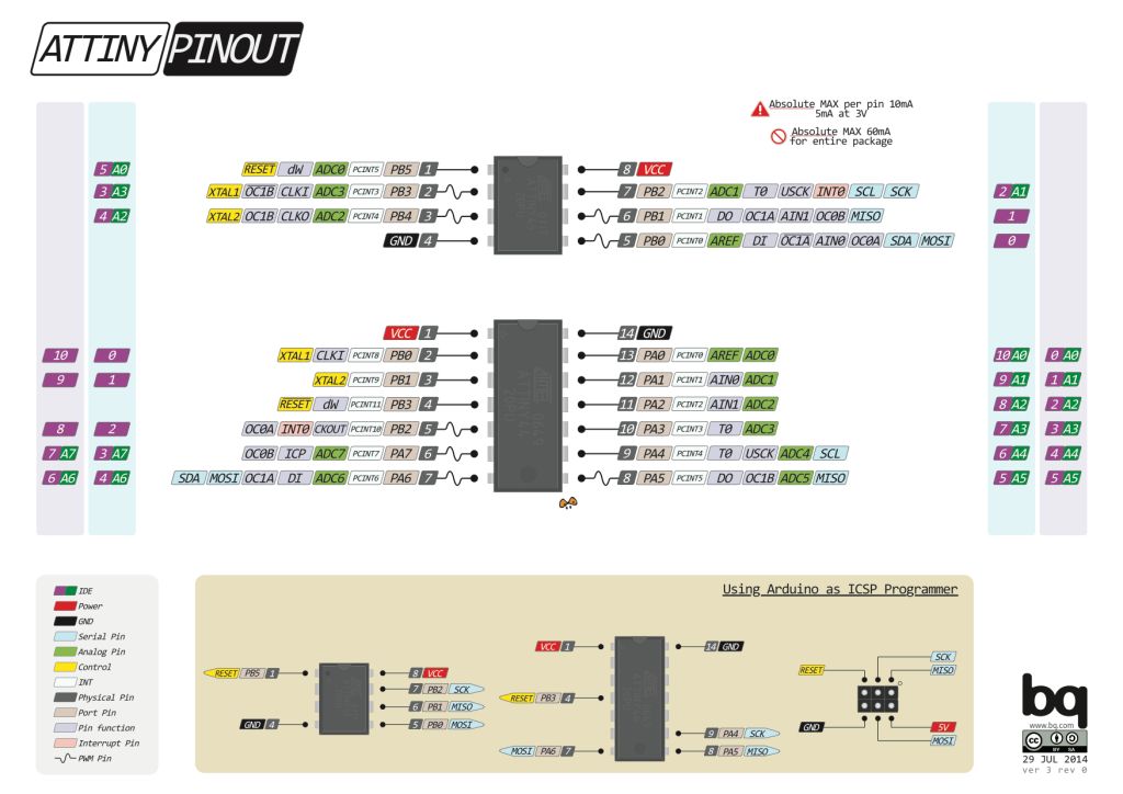
Pin Configurations
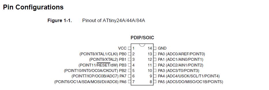
My understanding of the micro-controller is displayed below in the picture
Steps to program the hello world board
Follow the link ahead to understand how I programed the board to blink the LED using the button program. LED BUTTON
developing the user interface - processing
I chose to use processing this week to develop a GUI as it is similar to Arduino IDE. I found it easier to use, hence went ahead with it. "Processing is an open source computer programming language and integrated development environment (IDE) built for the electronic arts, new media art, and visual design communities with the purpose of teaching the fundamentals of computer programming in a visual context, and to serve as the foundation for electronic sketchbooks."-wikipedia I started by looking at a few tutorials to develop an interface in processing. I simultaneously repeated the steps as in the tutorial to develop and understand the process of developing the interface. The screen shots below explain my process.
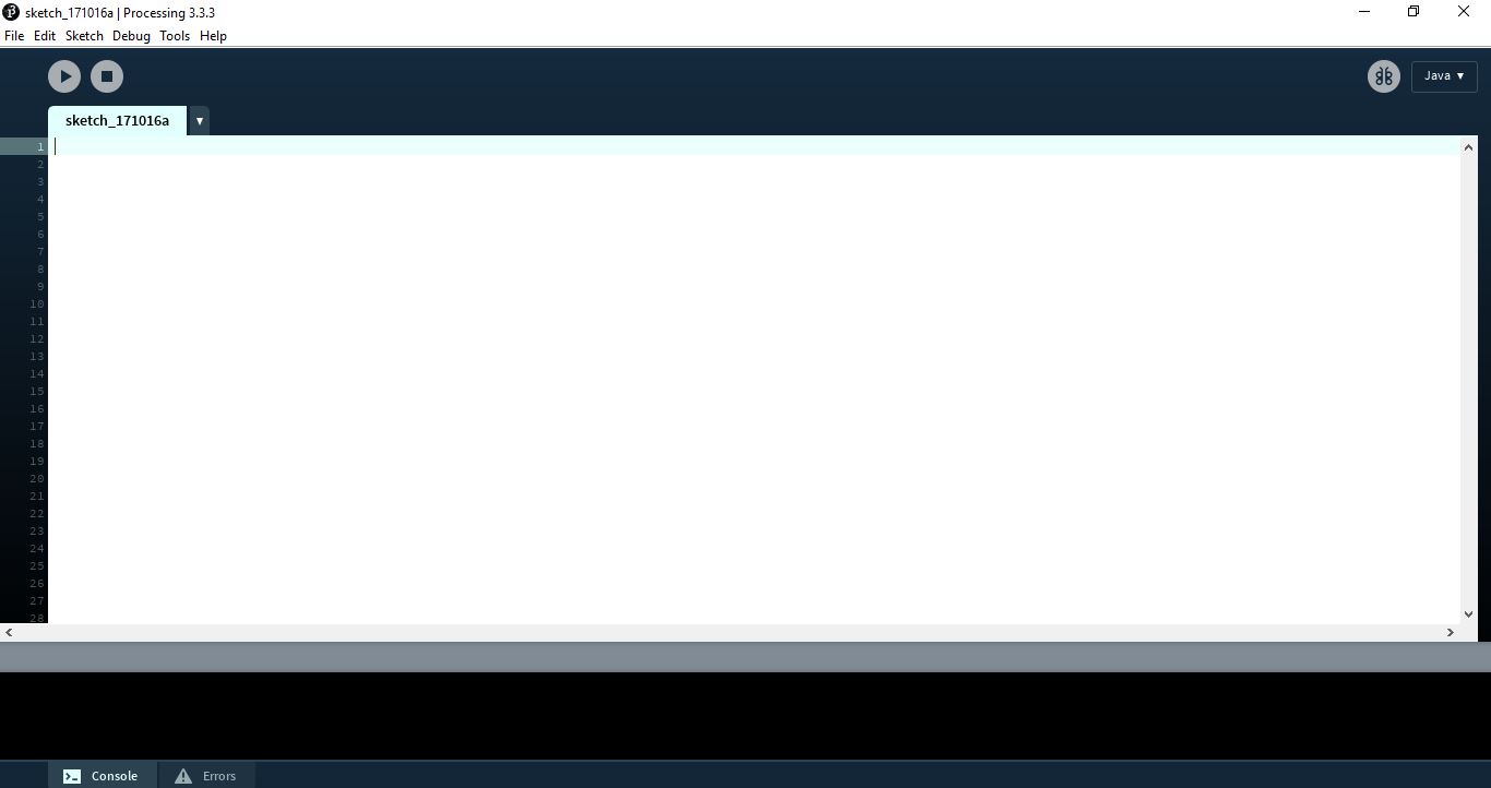
The below image shows the screen when processing is opened
developing the user interface for Hello Echo Board
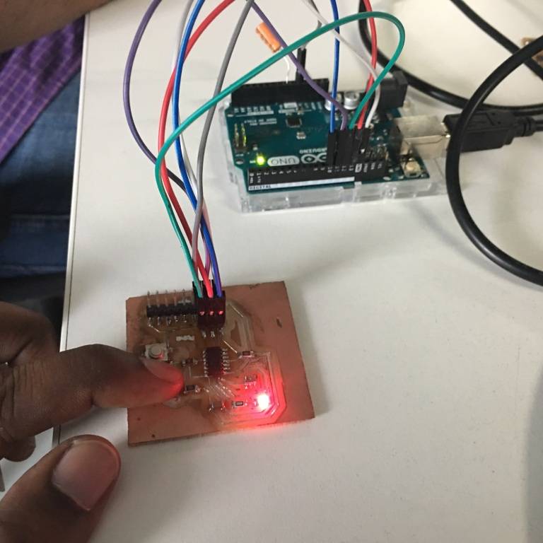
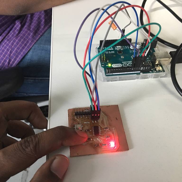
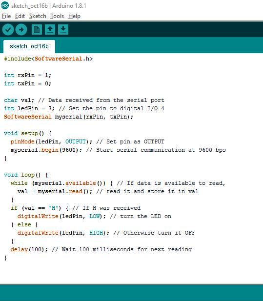
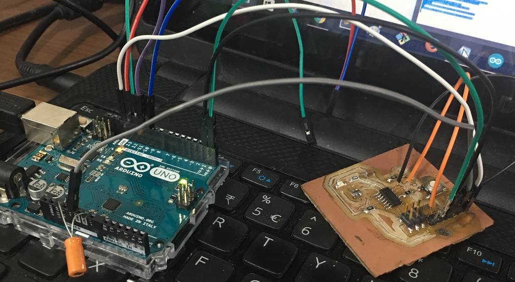
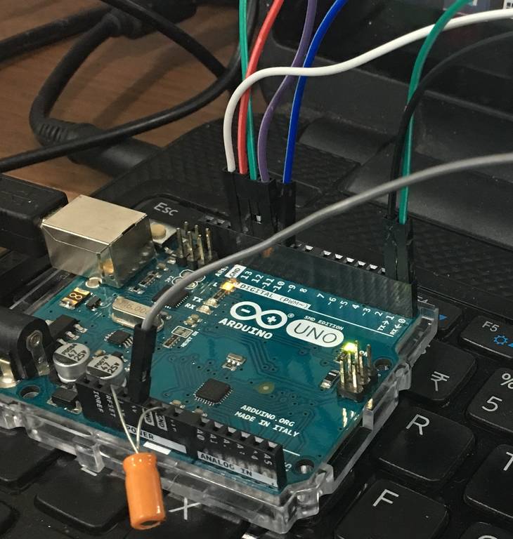
Since I used AtTiny 44 for my echo hello board, I needed to add software serial to get data via serial communication. I needed to send data from my GUI to make LED on my board blink. Hence, to begin with I modified the basic blink code of Arduino and added Software serial to the code to begin serial communication between the RX-TX pins. The image below shows the MISO, MOSI, SCK connections from my board to the Arduino via which I uploaded the code onto my board.
The codes can be seen below
    #include

int rxPin = 1;
int txPin = 0;

char val; // Data received from the serial port
int ledPin = 7; // Set the pin to digital I/O 4
SoftwareSerial myserial(rxPin, txPin);

void setup() {
  pinMode(ledPin, OUTPUT); // Set pin as OUTPUT
  myserial.begin(9600); // Start serial communication at 9600 bps
}

void loop() {
  while (myserial.available()) { // If data is available to read,
    val = myserial.read(); // read it and store it in val
  }
  if (val == 'H') { // If H was received
    digitalWrite(ledPin, LOW); // turn the LED on
  } else {
    digitalWrite(ledPin, HIGH); // Otherwise turn it OFF
  }
  delay(100); // Wait 100 milliseconds for next reading
}
The image shows the codes that I used to build the serial communication on my board.
Next, I used the basic simplewrite sketch of processing and modified it to develop my own customized GUI. The modified codes can be viewed below:
  /**
 * Simple Write.
 *
 * Check if the mouse is over a rectangle and writes the status to the serial port.
 * This example works with the Wiring / Arduino program that follows below.
 * modified by Clement Burga
 */
    import processing.serial.*;

Serial myPort;  // Create object from Serial class
int val;        // Data received from the serial port

void setup()
{
 size(200, 200);
 // I know that the first port in the serial list on my mac
 // is always my  FTDI adaptor, so I open Serial.list()[0].
 // On Windows machines, this generally opens COM1.
 // Open whatever port is the one you're using.
 printArray(Serial.list());
 String portName = Serial.list()[0];
 myPort = new Serial(this, portName, 9600);
}

void draw() {
 background(255);
 if (mouseOverRect() == false) {  // If mouse is over square,
   fill(0);                    // change color and
   myPort.write('L');              // send an H to indicate mouse is over square
 }
 else {                        // If mouse is not over square,
   fill(204);                      // change color and
   myPort.write('H');              // send an L otherwise
 }
 rect(50, 50, 100, 100);         // Draw a square
}

boolean mouseOverRect() { // Test if mouse is over square
 return ((mouseX >= 50) && (mouseX <= 150) && (mouseY >= 50) && (mouseY <= 150));
}
After doing the coding & writing the user interface program I uploaded the program to the board with the Arduino connected. I found out that there was no communication between the user interface & the board.
The exercise was to hover the cursor on the user interface to make the LEd blink on the board. I was not able to blink the LED due to the following errors.
- The board design did not contain connection between the Rx, Tx pins of the micro-controller to the FTDI
- Connections of the Hello World Board to the Arduino board were incorrect (Once the board is programmed for the LEd blink there is no need for the FTDI cable to be plugged with the board)
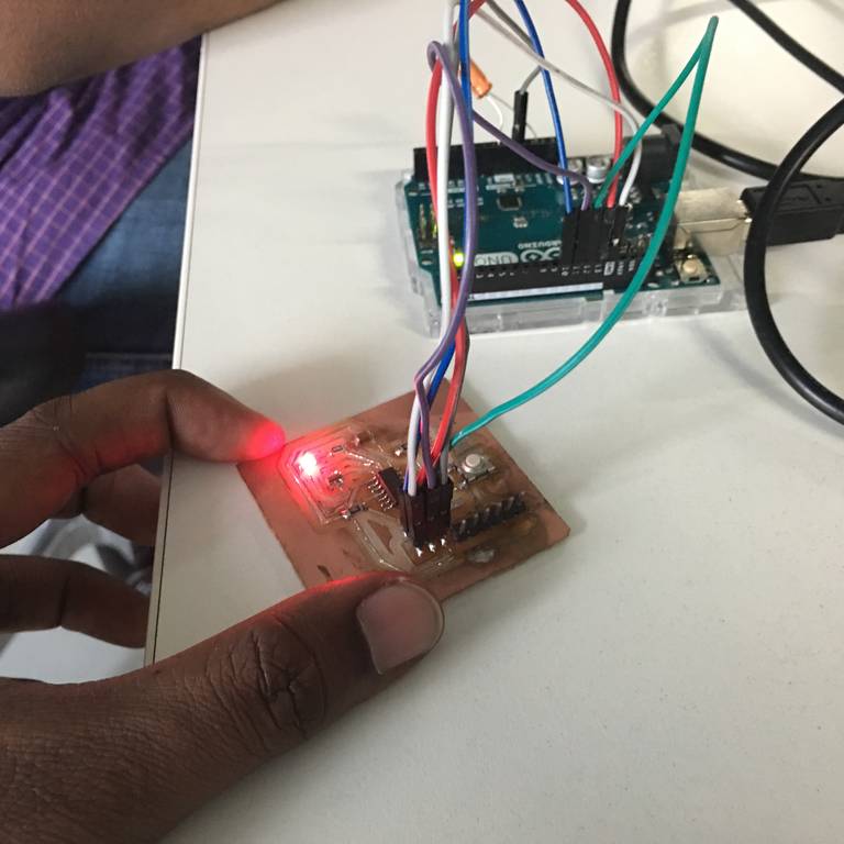
The below image shows how to connecT the Rx & Tx pins of the micro-controller to the FTDI pins.
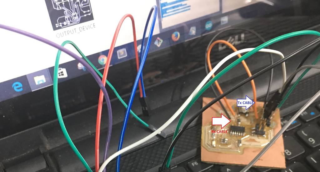
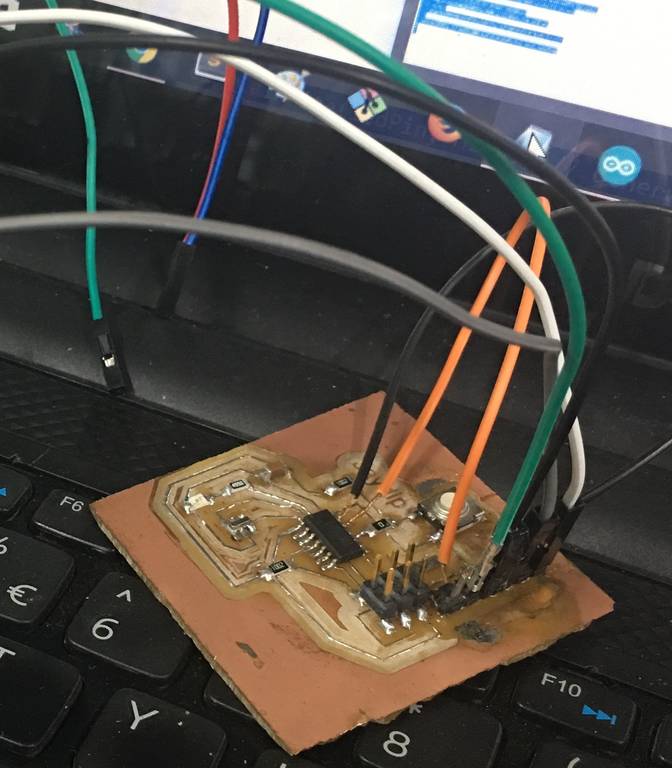
To correct this error I connected th Rx & Tx pins of the board with Jumper cables as shown in the below image.
The next step was to just connect the Rx, Tx, GND, & the VCC of Arduino board to the FTDI pins of the Hello World Board. This can be seen in the image below
My LED Button operating video can seen below
LED_BUTTON-2 from Clement Burga on Vimeo.
My Board with User Interface using Processing video is shown below
PROCESSING_VIDEO-1 from Clement Burga on Vimeo.
learnings of this week
- This week I learnt a new software Processing for operating my boards as required
Files to download

This work is licensed under a Creative Commons Attribution-NonCommercial-ShareAlike 4.0 International License.