AVR - ATtiny 44 Micro-controller
A micro-controller is a small computer (SoC) on a single integrated circuit containing a processor core, memory, and programmable input/output peripherals. Program memory in the form of Ferroelectric RAM, NOR flash or OTP ROM is also often included on chip, as well as a typically small amount of RAM
The documentation for Atmel’s ATtiny44 MCU is a whopping 268 page pdf. Electronics was never my cup of tea. But I had to go through the data sheet to understand what the micro-controller is capable of doing & how it does.
Some of the features of the ATtiny 44 are as listed below:
- High Performance, Low Power AVR 8-bit Micro-controller
- 120 Powerful Instructions – Most Single Clock Cycle Execution
- 256/512 Bytes of In-System Programmable EEPROM
- Data Retention: 20 years at 85°C / 100 years at 25°C
- In-System Re-programmable Flash memory for program storage.
- Programmable Brown-out Detection Circuit with Software Disable Function
- Operating Voltage: – 1.8 – 5.5V
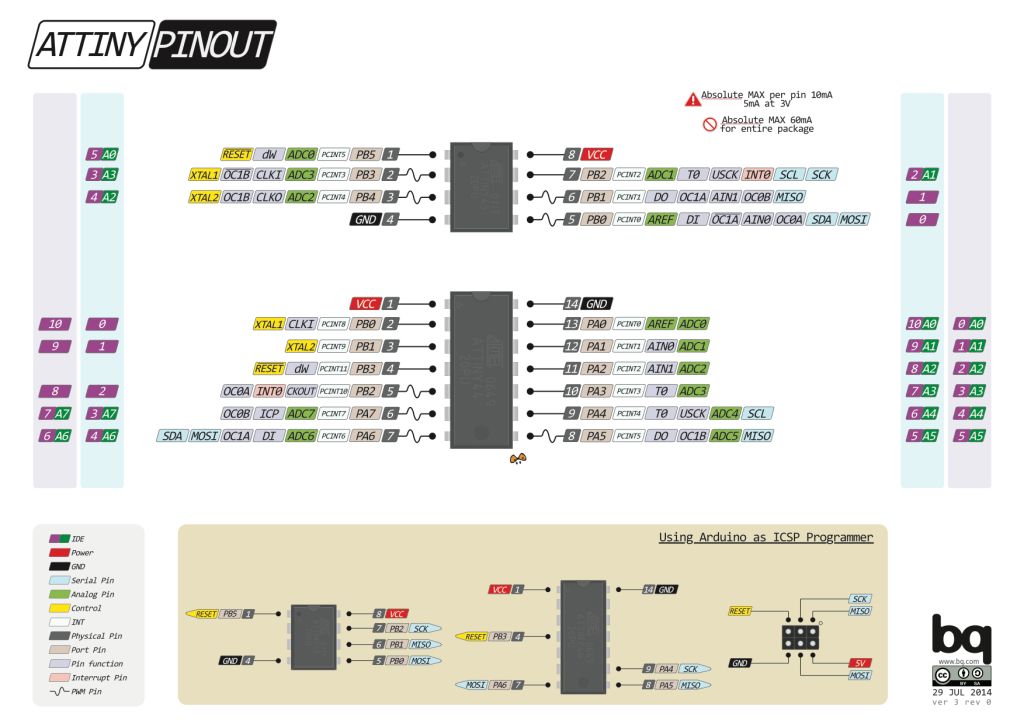
The Pin Configuration and Pin Descriptions in Section 1 are important - PighiXXX has created very nice color-coded pin-out diagrams for many processors including the ATtiny family, including pin mapping for the Arduino IDE:
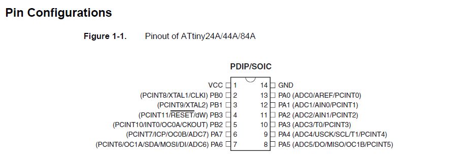
Pin Configurations
Preparing the board
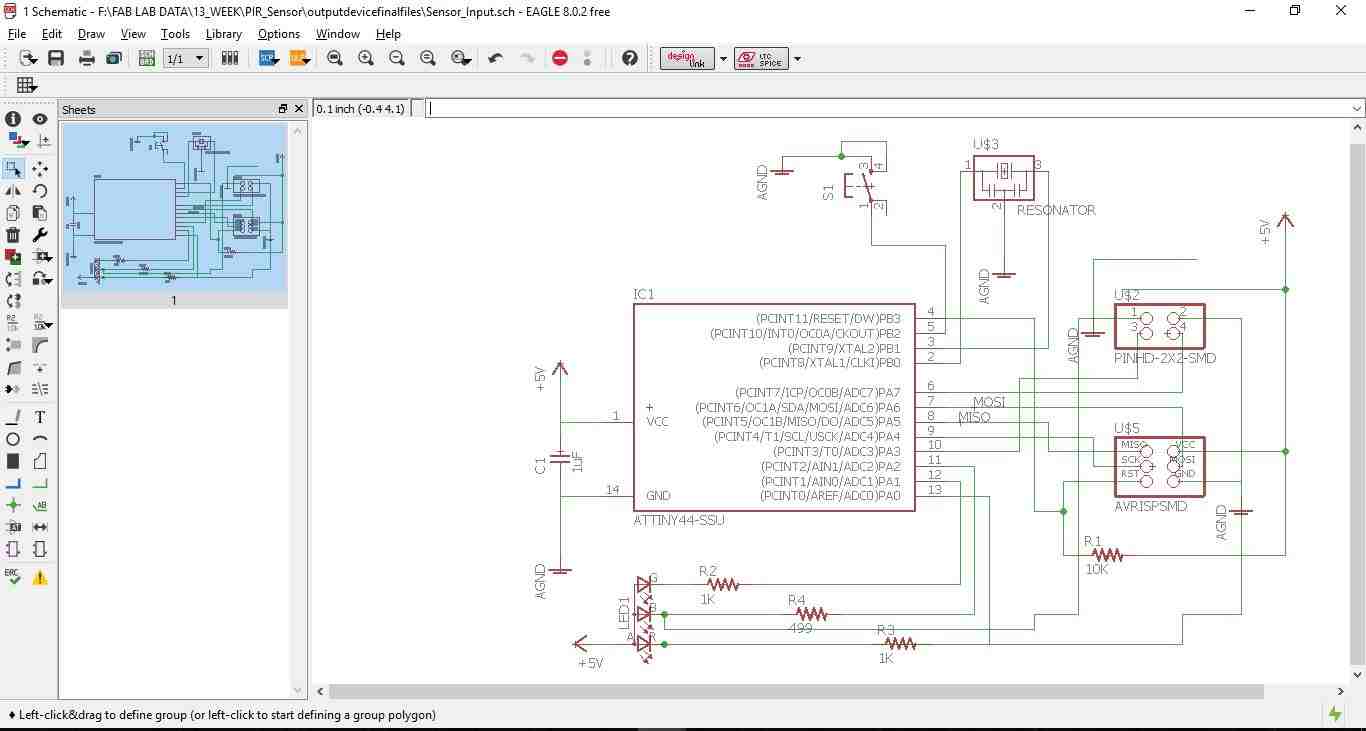
After understanding the ATtiny 44 then I prepared the schematic of the circuit using Eagle. The below images depict the schematic & the board.
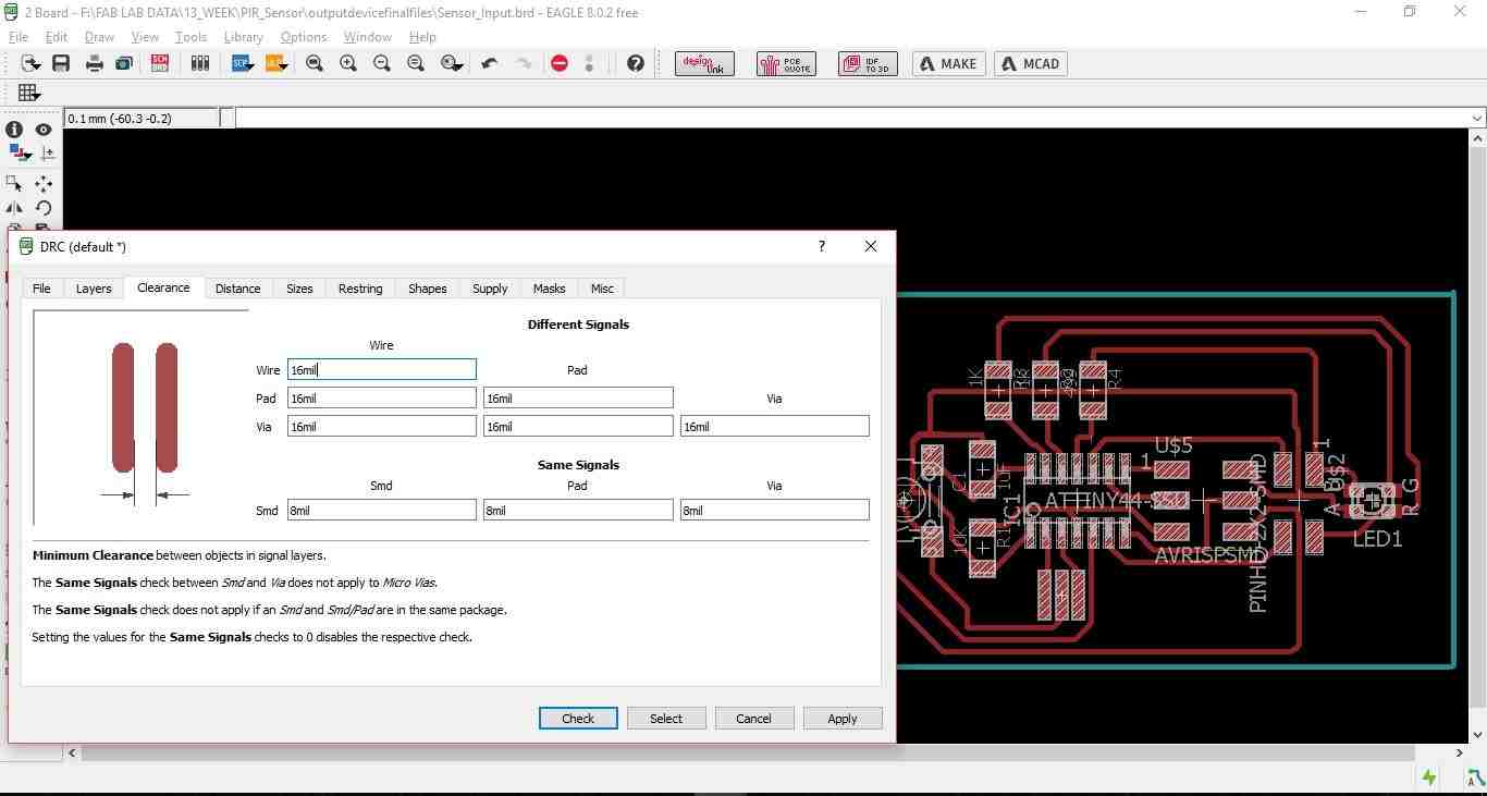
Then switch the tab to board & placing all the elements of the board to my satisfaction, For making the board I used the Auto routing option with the traces thickness 0.4mm an all the clearances kept at 16mill. Then I did the drc check as shown in the below image.
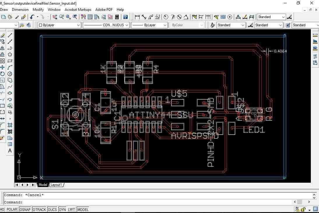
Some times the auto routing option keeps the traces thickness at 0.25mm which is not desirable for board milling. Hence it is always recommended to check the thickens of the traces by converting the board to .dxf format. Open the dxf file in Auto CAD and check the width of the traces as shown in th below image.
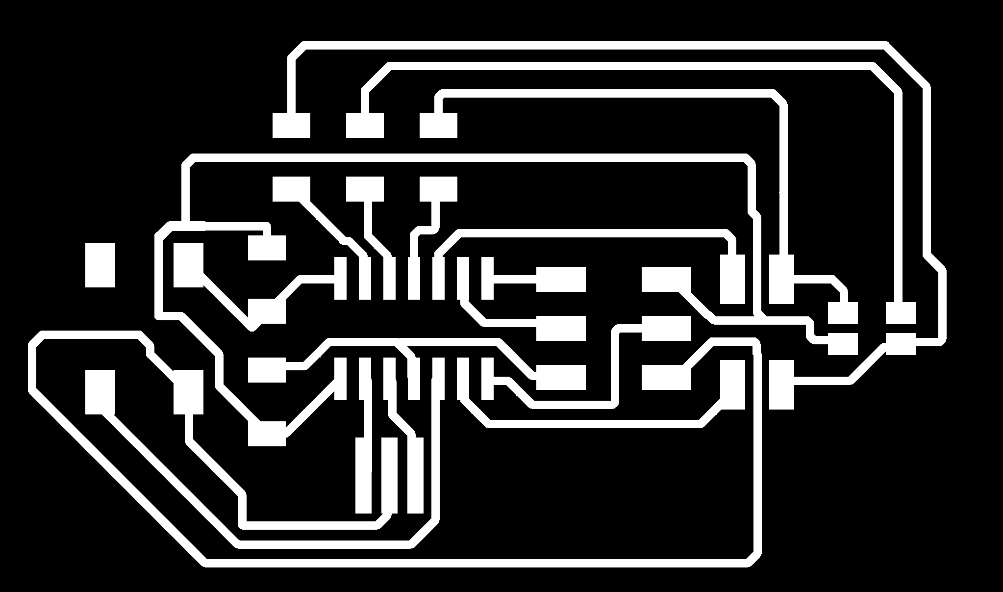
Once everything is ensured export the board to .png format for milling.
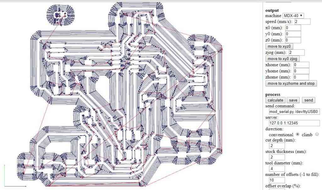
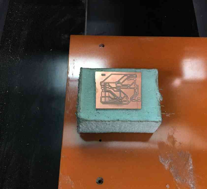
The below image shows the traces in the fab module using MDX-40 milling machine
Board milling in progress on the machine
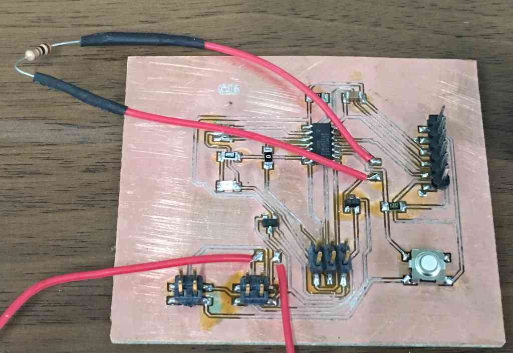
The final board after milling & soldering all the elements is shown in the below image. (image needs to be changed)
Programing the board for output device
The functioning of the board includes to write a C-Program & also use the Gestalt x-y node given by Neil.
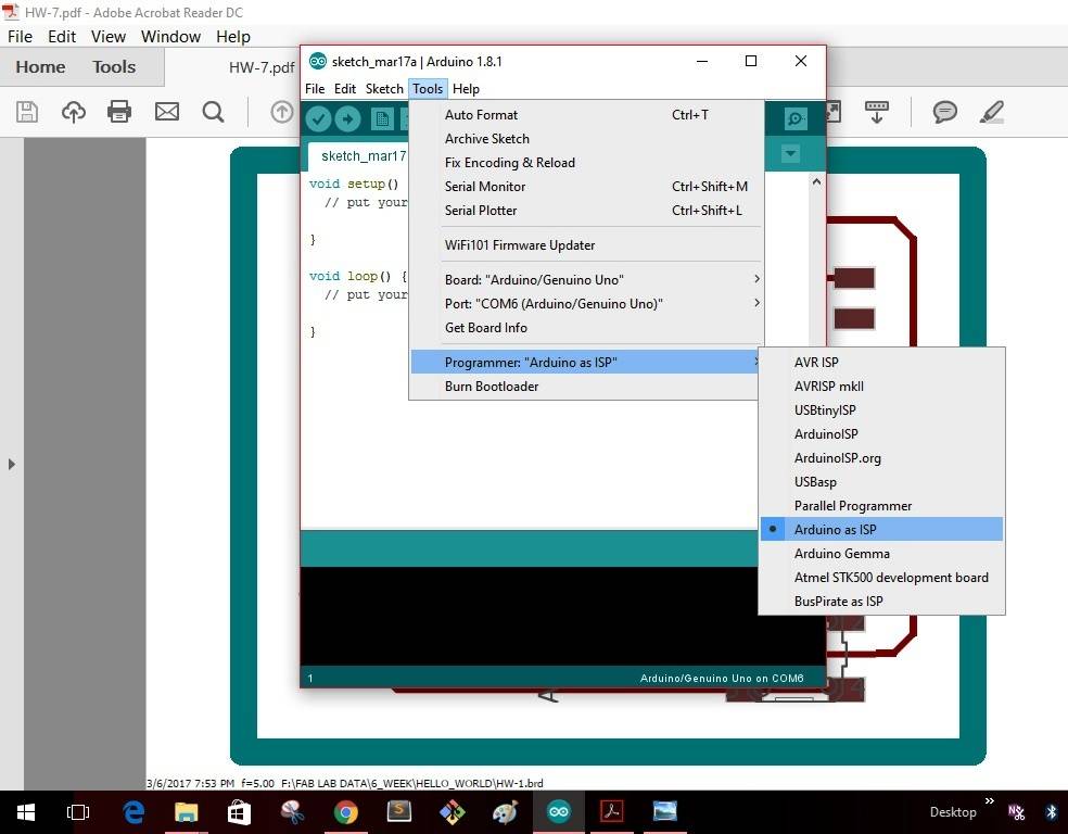
First I need to make the Arduino as an ISP by following the steps below.
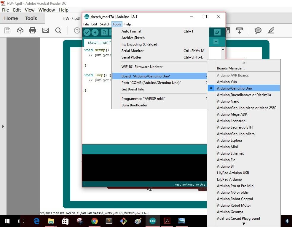
First I connected the Arduino board to my computer. I will make the Arduino board as a programmer to program my Board. Doing the following steps as seen in the below pics:
Step 1: In Tools ------- Board-------select "Arduino/Genuino Uno"--------
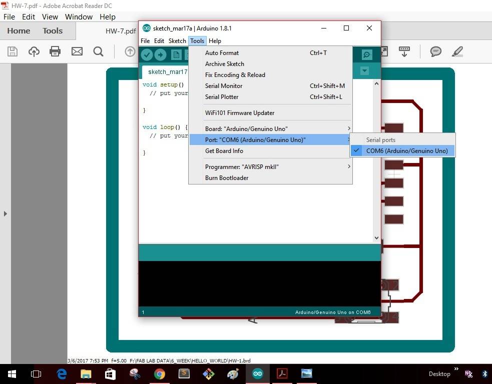
Step 2: In Tools ------- Port-------select "COM6(Arduino/Genuino Uno")--------
Step 3: In Tools -------Programmer-------select "Arduino as ISP"--------
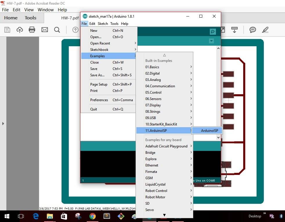
Step 4: In File -------Examples-------select "Arduino ISP"--------
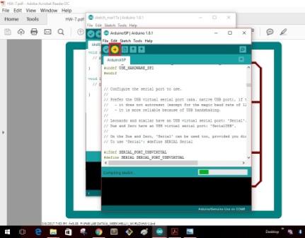
Step 5: As soon as I select the "Arduino ISP" the window as shown will pop up with a yellow icon as shown. Click the icon to upload the program into the Arduino board.
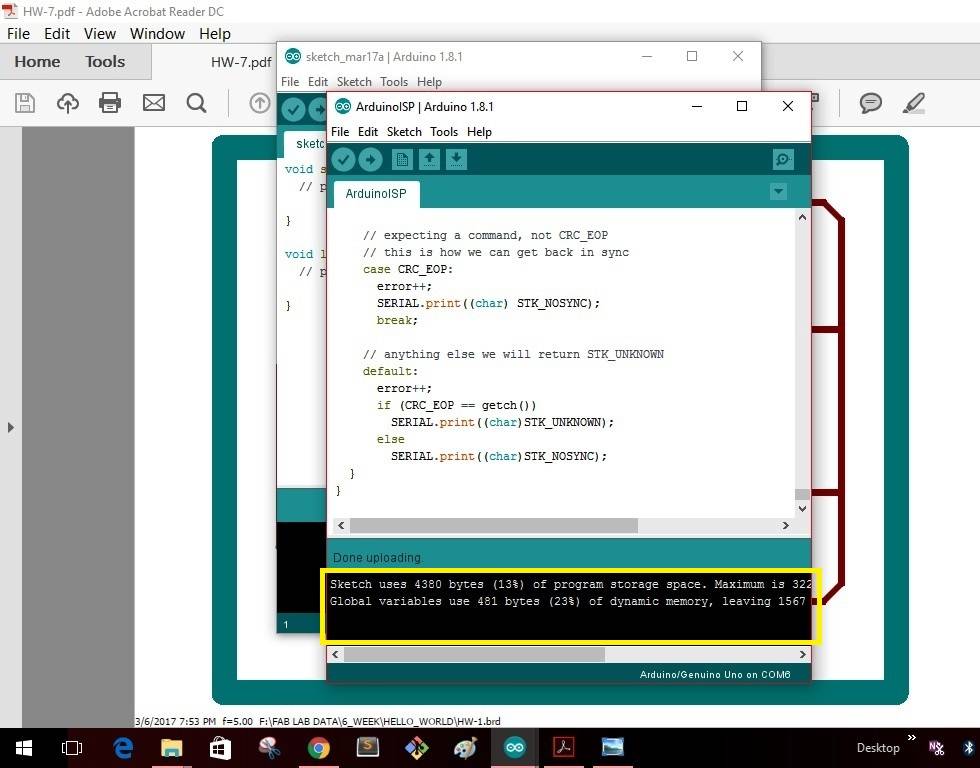
Once the uploading gets completed the window as shown below will give as message that uploading is completed.
This completes making the "Arduino" board as a programmer. I disconnect the board with my computer
I have written the below code for the operating the switch of the board.
#define F_CPU 1000000  //Define clock speed as 1Mhz
#include     //Import header file required for AVR micro-controllers
#include   //Import header file required for delay function
int main(void)
{
DDRA = 0b10000100;  //set PA7 & PA2 as output & all other pins as input
int flag;
flag=1;
//PORTA &= ~(1<<7); //Set PA7 low (Make LED OFF)
//PORTA |= (1<<2);

while (1) //Repeat the below actions continuously
{
if((PINA & (1<<3))==0b00000000 && flag==1)
{
PORTA ^= (1<<7); //Set PA7 high (Make LED ON)
PORTA ^= (1<<2);
flag = 0;
}
else if ((PINA & (1<<3))!=0b00000000 && flag==0)
{
flag = 1;
}
}
}
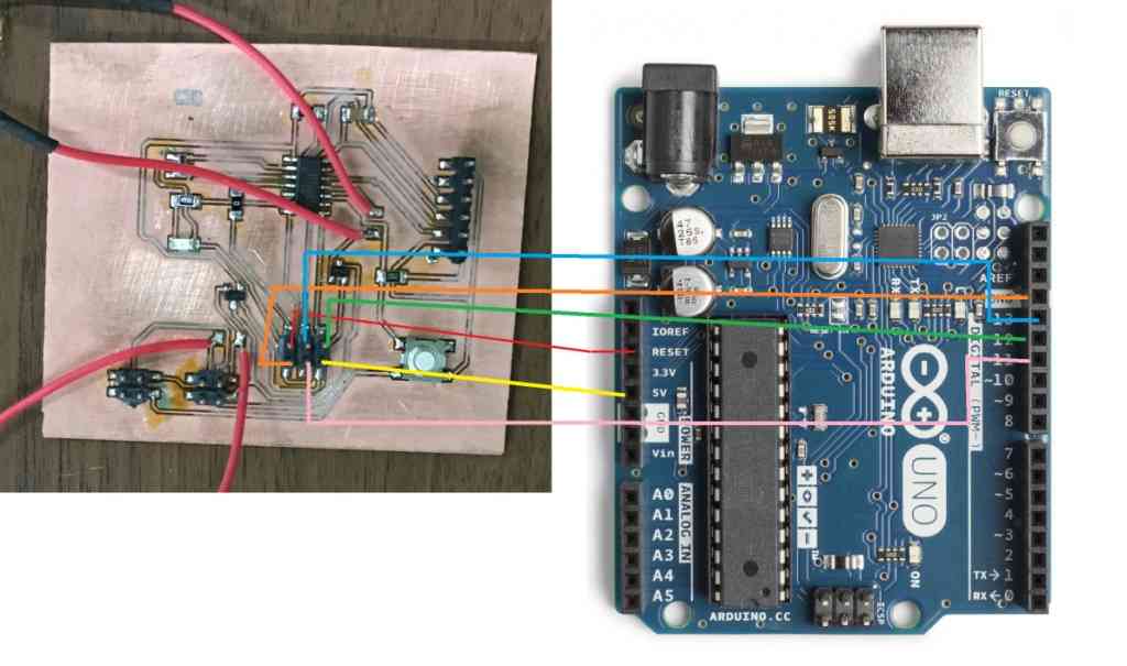
The next step is to connect my board with the Arduino board & burn the program into the ATtiny 44 micro-controller. The below image shows how the physical ISP pins of the board have to be connected to the Arduino board. Following the same representation I connected my board with the Arduino board as shown in the next image.

The next step is to connect the board with all the elements to check the working of the board with the program written into the micro-controller.
SPDT Relay
For this assignment I have used a Single Pole Double throw Relay which will function as a switch to Turn ON & OFF the stepper motor. The schematic of the SPDT Relay is shown in the image below. The simple working of this relay can be seen by following the link SPDT Relay

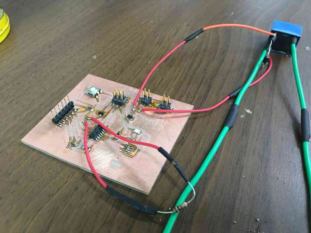
The below image shows how I connected the SPDT relay with my board.
The testing of the switch can be seen in the video
SWITCH_TESTING from Clement Burga on Vimeo.
Working with PYTHON
Python is an easy to learn, powerful programming language. It has efficient high-level data structures and a simple but effective approach to object-oriented programming. Python’s elegant syntax and dynamic typing, together with its interpreted nature, make it an ideal language for scripting and rapid application development in many areas on most platforms. I went through some of the commands used in Python. The detailed tutorial of Python can be referred following the link: PYTHON TUTORIAL
Installing gestalt node
I will be using stepper motor which I have previously used for MTM assignment of group activity. In total I will be using 4 stepper motors & 4 gestalt nodes for my project. I will explain the detailed process of how I went through the operation of stepper motor using gestalt nodes.
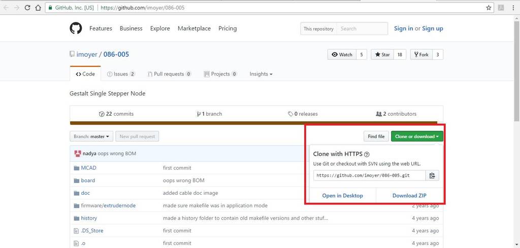
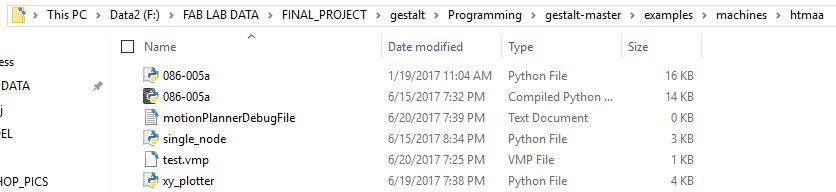
I first went to this site GIT Hub to download the package of gestalt node as shown in the below image.
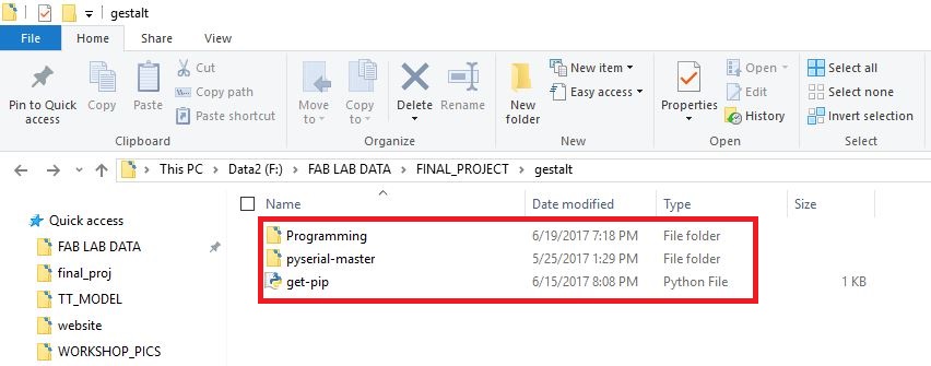
The following folders will be present after downloading the package.
Install Python 2.7 —not Python 3.4. There are numerous differences between Python 2 and 3, and Gestalt has been built with Python 2. Make sure to add Python to your PATH so you can run it from a command prompt.
Install pySerial . There are many ways to do this, but perhaps the most “correct” way to do it is to first install pip, the Python package manager. pip comes with Python 3.4 and later, but since we’re on Python 2, we will have to go through a jankier process.
First, download this script for installing pip. (It’s not a virus.) Then, run the following commands:
python get-pip.py
python -m pip install pyserial
(python -m pip is an alias for just pip on Windows.)
Build the gestalt software. First, check out a copy of the repository. Then, go to the directory and run
python setup.py install
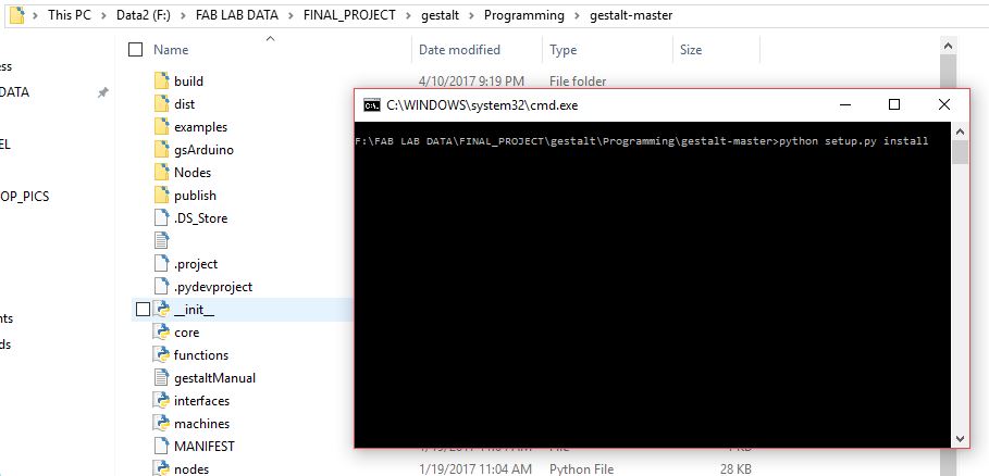
This builds the code and installs it locally so you can import gestalt from Python code. Otherwise doing this will throw an error, and you may be tempted to make a bunch of copies of the files to try and fix it, which is sure to cause more havoc.
Test! At this point you should be able to get a basic two-node, two-axis machine running with the provided xy_plotter.py demo file.
To Use the gestalt node
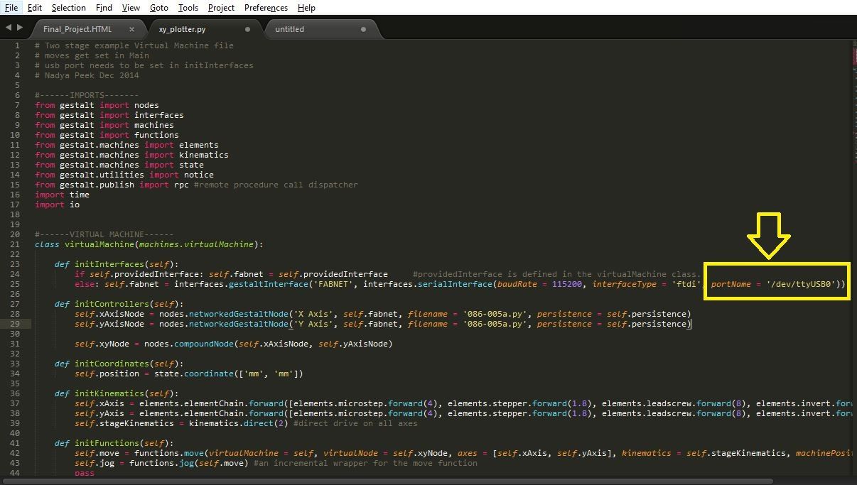
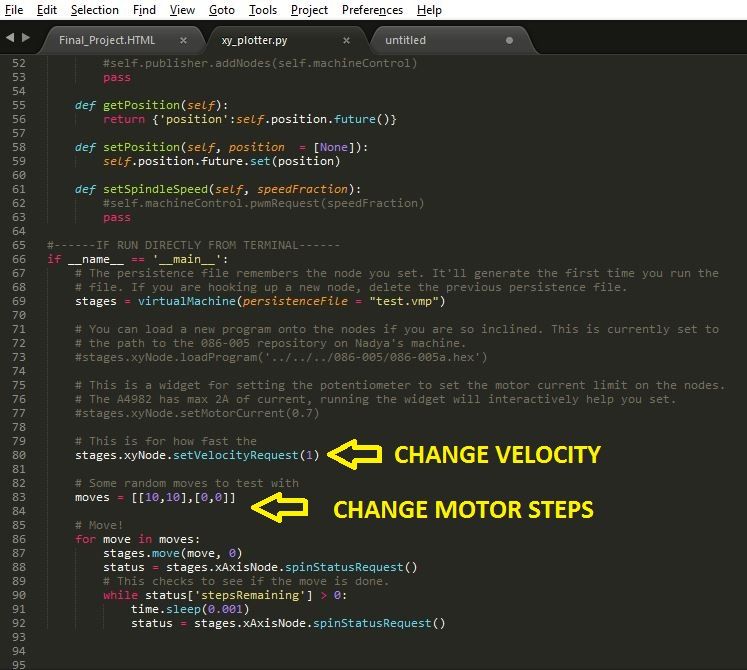
In any of the text editor open the file xy_plotter python file & pre written code can be seen.
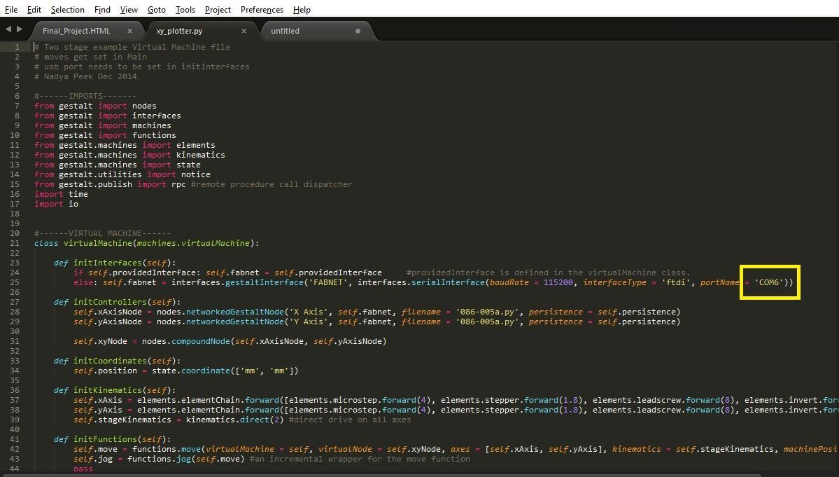
The immediate thing to do is to change the default COM port from /dev/ttyUSB0 to the COM port as can be seen in respective Device manager of the particular laptop. Here in my laptop its COM6
The next step is to change the value of the velocity & steps of the stepper motor as per our requirement.
Then go to the directory & open command prompt window & type the below command
python xy_plotter.py
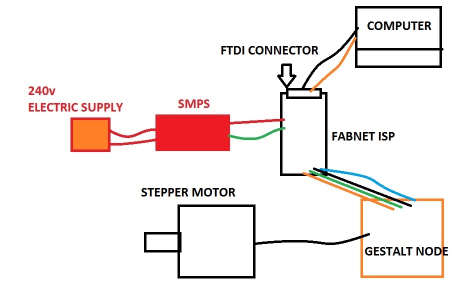
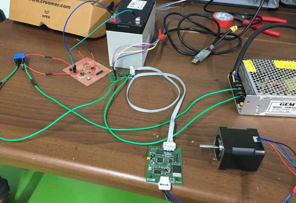
Before hitting the enter button ensure that the connections to the gestalt node are made as shown in the below image. Also ensure that the power supply is ON before hitting the enter button.
The extracts of the working video of the stepper motor is shown in the video below
STEPPER_MOTOR from Clement Burga on Vimeo.
learnings of this week
- This week I learnt a new software Python for operating the stepper motors.
- This week I learnt to work with Gestalt nodes for operating the stepper motors.
- How to connect the Fab ISP with the Gestalt nodes for operating the stepper motors.
Files to download

This work is licensed under a Creative Commons Attribution-NonCommercial-ShareAlike 4.0 International License.